

Page 1
MCS
Miniature Collimating Sight
USER’S MANUAL
Important Export Restrictions! Commod ities, pro ducts, technologies and s ervices of this
manual are cont rolled by the U. S. Depar tment of State O ce of Defense Trade Controls, in
accordan ce with International Trac in A rms (ITAR), Title 22, Code of Federa l Regulations Part
120-130 and/or by the Exp ort Admini stration Re gulations (E AR) of U.S . Departm ent of Com merce. At an y time when a lice nse or a written approval of the U. S. Government is applicable
to it, it is illegal and strict ly forbidden to expor t, intend to export, transf er in any other manner
whatso ever, sell any hardware o r technical data, prov ide any ass ociated ser vice to a ny nonU.S. resident, beyond o r within the Unite d States territory, until the valid license or written
app rov al ha s be en is sue d by t he De par tme nts o f th e U.S . Go vern men t hav ing j uri sdic tio n. A dditional ly U.S. law prohibits the sale, trans fer, or expor t of items to certain re stricted pa rties,
destina tions, and em bargoed count ries, as iden tied on lis ts maintained by the U.S. Department o f State, th e U.S. De partment of Commerce, and the U.S. Depar tment of Treasur y. It is
the respons ibility of the Customer to be awar e of these list s. The sale, transfer, tran sportation,
or shipment outside of the U.S. of any product prohibite d or restricte d for export without
complyi ng with U. S. export control law s and regul ations, inclu ding proper export licensing,
docume ntation or auth orization, is unlawful and may result in ci vil and/or crim inal penalties
and/or const itute a federal cr ime. Diversion con trary to U.S. law is s trictly prohib ited.
Page 2

SAFETY SUMMARY
Before operating this product, study carefully this Manual.
Armasight MCS Miniature Collimating Sight is a precision electro-optical
instrument and requires careful handling. To avoid physical and equipment damage when using the MCS, follow all WARNINGS, CAUTIONS and
NOTES.
Denition of the following alerts throughout this Manual:
WARNING — Identies a clear danger to the person operating the equip-
ment.
CAUTI ON — Identies risk of damage to the equipment.
NOTE — Ser ves to highlight essential procedures, conditions, statements,
or convey important instructional data to the user.
WARNING:
When installing the equipment on a weapon, be sure the weapon is
CLEAR and SAFE-ON before proceeding.
CAUTI ON:
Do not dismantle the equipment.
Keep the equipment clean. Protect it from moisture, sharp tempera-
ture drops and shocks.
DO NOT over-adjust the controls by forcing them beyond their end
of travel.
DO NOT leave the equipment switched on during stops in operation.
Do not store the equipment with the battery still in it.
Dry thoroughly each item before replacing into the storage carton.
NOTES:
Zero the weapon prior to installation and boresight adjustment of the
MCS.
We provid e the informat ion in this manu al for the intr oduction pu rpose only; t he contents
may unde rgo furthe r changes wi th no commitm ent by Armasi ght to keep c ustomers not ied abou t the same.
Armasig ht assumes n o responsibi lity for any misprints or other mistakes tha t may be co ntained i n the present.
©2012 Armasight. All ri ght reserved .
2
Page 3

1. DESCRIPTION AND DATA
1.1 DESCRIPTION
The Armasight MCS (Miniature Collimating Sight) is a micro-LED collimating sight ideal for “both-eyes open”, rapid-target acquisition. The MCS is
rugged, lightweight, and is designed to mount onto many existing optics
as well as MIL-STD-1913 Picatinny and Weaver-st yle rails.
The Armasight MCS is the only sight in its class and on the market that features a dual-reticle pattern. The user can select a 3.5 MOA “Dot” reticle or a 20
MOA “Ring” reticle pattern, depending on mission requirements. The MCS is
compatible with night vision devices of all generations. Reticle intensity is
regulated by an automatic brightness control sensor, which can be overridden by the user and turned to maximum brightness mode if required.
The MCS is designed to signicantly improve the accuracy and ecienc y of
virtually any weapon, from handguns and pistols to assault ries and light
machine guns. The compact size and versatility of the MCS make it an ideal
secondary or backup optical sight. Accurate and reliable, the Armasight
MCS features 1.2 MOA/click windage and 1.5 MOA/click adjustments. A
unique optical design allows for a parallax-free, “always on the center”
reticle.
The MCS is waterproof; it has been tested against salt fog, dust, and vibration. It has been drop-tested and mounted on a variety of rearms as they
red thousands of rounds. The Armasight MCS complies with MIL-STD 810 G
standards. The MCS features a unique pivot lens cover that has anti-reective coating, and it works on a single, easy to replace CR2032 3V battery.
1.2 KEY FEATURES
Tactile click stops for windage & elevation adjustments
–
A switchable 3.5 MOA dot to 20 MOA ring reticle pattern
–
Automatic brightness control of the reticle based on the target
–
area brightness
Rapid target acquisition
–
True night vision compatible mode
–
User congurable open or tube sight mode
–
Riescope mounted or weaver mounted variations
–
Battery change with no change in zero
–
Large heads-up display with wide eld of view
–
3
Page 4

Parallax-free performance
–
Submersible in up to 10m (33 ft) of water
–
Push-button controls for reticle switching, manual override of
–
auto brightness, night vision mode, and on/o function
Anti-reective coatings on lens covers, to maintain covertness
–
Limited Two-Year Warranty
–
1.3 SPECIFICATIONS
Magnication 1x
Exit Pupil 20x15 mm
Eye Relief from 100 to 500 mm
Parallax (at 100 m) less than 0.5 MOA*
Windage & Elevation Adjustment
Range
Windage Adjustment Accuracy 1 click=1.5 MOA (45 mm at 100 m)
Elevation Adjustment Accuracy 1 click=1.2 MOA (36 mm at 100 m)
Reticle Pattern Conguration Red Dot / Circle (interchangeable)
Reticle Pattern Size:
- Dot
- Circle
Reticle Brightness Adjustment Auto / Manual (MAX or MIN positions)
Power Supply 3V Lithium Batter y (CR2032)
Batter y Life (with Dot Pattern):
- at MIN Brightness Mode
- at MAX Brightness Mod
Operating Temp from -40°C to +50°C
Waterproof 10 m for 1 hour
Mounting System for Picatinny Rail or
Dimensions 48x40x47 mm (ver. for Picatinny rail)
Weight 65 g
* MOA = Minute of Angle
±1. 5°
3.5 MOA (10 cm at 100 m)
20 MOA (60 cm at 100 m)
20 000 hours
250 hours
for ACOG 4x32 (Trijicon) riescope
48x44x52 mm (ver. for ACOG 4x32)
4
Page 5
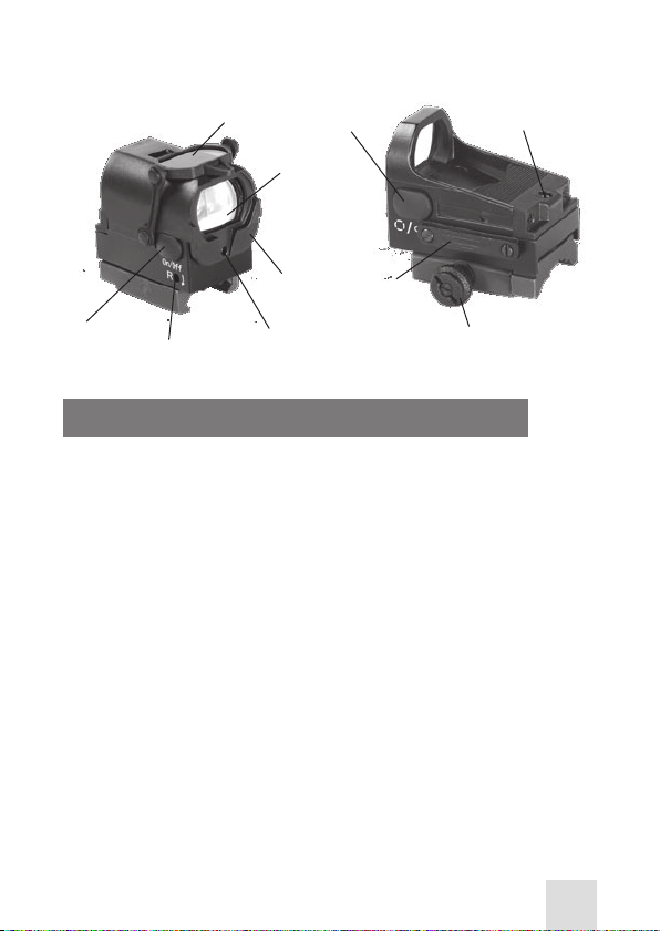
1.4 LOCATION OF MAJOR COMPONENTS
LENS
COVER
IMAGE
WINDOW
LEFT
BUTTON
ELE VATI ON
ADJUSTMENT
RIGHT
BUTTON
WINDAGE
ADJUSTMENT
PROTECTIVE
COVER
PHOTO SENSO R
Figure 1. MCS Components
BAT TER Y
HOLDER
MOUNTING
SCREW
2. SAFETY, CARE AND HANDLING
WEAPON SAFETY: Prior to mounting the MCS on your weapon, verify that
the weapon is cleared. If you are not sure how to clear your weapon, please
see the accompanying operator’s manual for the weapon platform that
you using to mount the sight.
FCC COMPLIANCE: The MCS complies with Part 15 of the FCC Rules. Operation is subject to the following conditions: (1) this device may not cause
harmful interference; and, (2) this device must accept any interference received, including interference that may cause undesired operation.
When a sudden increase in resistance is felt in the elevation or windage
adjustment shafts, the end of the adjustment range has been reached. Do
not turn the adjustments any farther or serious damage may occur to
the sight.
Never clean the glass surface with a dry cloth or paper towel; always damp en the glass surfaces prior to cleaning.
All moving parts of the sight are permanently lubricated. Do not tr y to lubricate them.
Do not use deteriorated or corroded batteries. Inspect batteries for rips,
tears, dents, or cuts in their casing. If you nd any leakage on the battery, it
could adversely aect operation of the sight.
5
Page 6

3. OPERATING PROCEDURE
RIGHT O N/OFF &
MAX BRIGHTNESS
LEFT DO T/RING &
NIGHT VI SION
WINDAGE
ELE VATI ON
BAT TER Y
COMPARTMENT
Figure 2: MCS
ON/AUTO BATTERY CHECK: Pressing and releasing the right button will
turn the sight on in auto-brightness mode. If the battery has less than 10%
power remaining, the reticle will blink after the sight powers on. If the
reticle blinks, the battery should be replaced. The battery condition can
be checked at any time by powering o and then immediately powering
on the unit.
OFF: While the sight is on, pressing and releasing the right button will turn
the sight o.
AUTOBRIGHTNESS OVERRIDE: Pressing and holding the right button for
two (2) seconds will place the reticle in MAX brightness mode. This mode
can be used to override the auto-brightness function, in case the photo
sensor becomes damaged or blocked. To return to auto-brightness mode,
press and hold the right button for two (2) seconds.
CHANGING BETWEEN RETICLE PATTERNS: Pressing and releasing the left
switch will toggle the reticle pattern from a 3.5 MOA dot to a 20 MOA ring.
The 20 MOA ring allows for faster target acquisition in CQB (close-quarters
battle) conditions, while the 3.5 MOA dot allows for greater precision when
shooting at longer-range targets.
3.5 MOA
20 MOA
Ø 3.5 MOA
CIRCLE
3 MOA
DOT
Figure 3: Reticle Patterns
6
Page 7

NIGHT VISION MODE: The MCS is compatible with Generation II, III, III+
and IV+ Night Vision Devices. In the night vision mode, the reticle brightness is low enough that when viewed with a night vision device, the reticle
image does not bloom.
To activate night vision mode, turn the sight on. Once the sight is on, press
and hold the left button for two (2) seconds. The reticle can now be seen
when a night vision device is placed behind it. To exit night vision mode,
press and hold the lef t button for two (2) seconds; the sight will return to
daytime operating mode.
POWER CONTROL: Maximum brightness, used in conjunction with the
manual override of all automatic controls and the 20 MOA ring mode, uses
more power than the auto-brightness 3.5 MOA dot mode. To maximize battery life, the MCS will automatically switch to 3.5 MOA dot auto-brightness
mode after 20 minutes of inactivity when in 20 MOA or max-brightness
mode.
REPLACING THE BATTERY: If the reticle ashes after the sight is turned on,
the batter y should be replaced. To remove the old battery, loosen the two
athead screws on the battery compartment using a small athead screwdriver or a similar tool. Pull the battery compartment out. To avoid losing
the screws, do not remove them completely. Remove the old battery from
the compartment and replace
it with a new CR2032 battery,
with the negative end facing
BAT TER Y
HOLDER
CR2032
up (as shown on the side of
your sight). Replace the battery compartment and tighten
the screws until they are secure. Do not over-tighten the
screws.
SCREWS
Figure 4. Replacing the Battery
PROTECTIVE LENS COVER: The MCS is equipped with a protective lens
cover that is necessar y for several reasons; the cover provides protection
for the lens and laser diode, keeps the optical path free of debris, and prevents unwanted light from obscuring the sight’s image and reticle.
The cover has three congurations. When the sight is not being used, a tab
on the lens cover blocks the photo sensor. This matches the sight in darkness, which prolongs battery life and protects the lens while it is not in use
(see Figure 5A).
In its normal operating mode, the lens cover is placed on the top of the
7
Page 8

protective cover. This allows for a clear view through the sight ’s window,
and restores the auto-brightness function (Figure 5B).
If the target background is extremely bright (i.e., glare bouncing o of the
ground, as is common in desert and wet environments), the lens cover acts
as a light lter. In this conguration, the tab on the lens cover is ipped up
to allow the photo sensor to function properly (Figure 5C).
The protective cover is plastic and snaps onto the MCS. No special tools
are required to install or remove this cover. When the cover is removed, the
sight can be used as a normal, open sight.
A B C
A - lter in place, sensor covered; B - sensor uncovered; C - lter o
Figure 5: MCS with Protective Housing
4. MOUNTING INSTRUCTIONS
The Armasight MCS comes in two versions (models): one with a mount for a
standard Picatinny rail (optical axis height is equal to 38 mm); and a second
one that can be mounted onto an ACOG 4x32 (Trijicon) riescope (optical
axis height is equal to 47 mm). For your convenience, the Armasight MCS
can be mounted the collating sight onto a weapon without any specialized
adapters.
4.1 MOUNTING ONTO A PICATINNY RAIL
The Armasight MCS Picatinny mount model can
be attached to the M16/ M4 Picatinny-style rail.
To do this, loosen the horizontal xation screw.
Place the scope onto the Picatinny rail, and verify
that the mount aligns with the rail. Re-tighten
the horizontal xation screw (Figure 6).
HOR. FIX ATION SCREW
Figure 6. Picatinny Mount
8
Page 9

4.2 MOUNTING ONTO AN ACOG 4X32
TRIJICON RIFLESCOPE
The Armasight MCS ACOG 4x32 (Trijicon) riescope model has two brackets with screw-holes,
to be used when mounting the sight onto an
ACOG 4x32 body (rather than the Iron Backup
Sights). Place the Armasight MCS onto the ACOG
4x32 body as shown in the picture to the right.
Screw the two set screws (included) in tightly
with a athead screwdriver (Figure 7).
BRACKET S WITH
SCREWHOLES
Figure 7. ACOG Mount
CAUTI ON:
Before mounting or testing the MCS, verify that your gun is not loaded. Always use proper gun safety and handling procedures.
5. ZEROING PROCEDURES
The MCS features click mechanisms for elevation and windage adjustments.
The adjustment mechanisms are grooved and require a small screwdriver
or similar tool to turn them. For both elevation and windage, each click will
change the bullet’s point of impact 1.5 Minutes of Angle (MOA), 3/4 inch at
50 yards, or 1.5 inches at 100 yards. To move the point of impact UP, turn
the elevation adjustment counterclockwise. To move the point of impact to
the RIGHT, turn the windage adjustment clockwise.
The MCS elevation and windage adjustments are
factor y collimated so that the bore of the rie is
parallel to the mounting rail. The sight should
be close to mechanical zero when mounted on
a properly installed rail. Do not turn the adjustments before mounting the sight on the rearm.
Be sure to check that the mount and sight are securely mounted after the initial ring.
If you encounter an increased level of resistance
in the adjustments, the end of the adjustment
range has been reached. DO NOT turn the adjustments any farther, as this may cause serious damage to the sight.
ELE VATI ON
WINDAGE
Figure 8.
Elevation & Windage
Adjustment
9
Page 10

6. OPERATOR LEVEL MAINTENANCE
The operator is limited to replacing batter y, as well as cleaning the battery
compartment and outer housing surfaces of the sight.
6.1 REPLACING BATTERIES
See ‘Replacing the Battery’ on page 6. Do not use deteriorated or corroded batteries. Inspect batteries for rips, tears, or cuts in the housing. If
there is any leakage on the battery casing, it could adversely aect operation of the sight.
6.2 CLEANING INSTRUCTIONS
1. The optical system and the window are coated with anti-reective material. When cleaning the glass surfaces, you must rst blow away any dirt
and dust. Fingerprints and lubricants can be wiped o with lens tissue or
a soft cotton cloth that has been moistened with professional lens cleaner
or glass cleaner; both are sold in most camera stores. Never clean the glass
surface with a dry cloth or paper towel; always dampen the glass surfaces
prior to cleaning.
2. No maintenance is needed on the sight’s surface, although you may
occasionally want to wipe it o with a soft cloth. Only use water-based
cleaners, such as regular glass cleaner, ammonia, or soap and water. Never
use any solvent-type cleaners such as alcohol or acetone. Do not use gun
cleaner to clean or lubricate the Collating Sight.
3. All moving par ts of the sight are permanently lubricated. Do not tr y to
lubricate them.
4. Never disassemble the sight’s optical assembly! Disassembly will void
the warranty and damage the sight.
6.3 CLEANING
To clean the unit’s exterior, brush o surface dirt or sand with a soft brush
to avoid scratching the paint. Wipe the unit down with a damp cloth to re move all remaining grime, followed by a dry cloth to remove moisture. For
further protection against dirt and dust, use a silicon-treated cloth to wipe
the outside of the unit (be careful not to touch any of the optical lenses).
The optics can be cleaned using an optical quality lens tissue (similar to
those used to clean glasses or binoculars). The brightness sensor should
also be regularly cleaned with optical tissues.
10
Page 11

7. TROUBLESHOOTING
Common problems that may occur with your MCS or the detection and
viewing tests, as well as actions you can take to correct them, are listed in
the Troubleshooting Table, below. This table does not list all of the malfunctions that may occur with your device. If you experience a malfunction that
is not listed on this table, please contact Armasight or your MCS retailer
NOTE:
Before you use this table, be sure that you have performed all normal
operational, safety, care and handling checks and procedures. If
you experience a malfunction that is not listed in this table, notify
Armasight or your MCS retailer.
TABLE 1. TROUBLE SHOOTING GUI DE
PROBLEM POSSIBLE CAUSE ACTION
The batteries are n ot
The sight will not
power up.
If these acti ons fail, please contact Cust omer Support.
The reticle is
fuzz y/ has a ‘halo’
eect.
If the proble m persists, please co ntact Customer Suppor t.
installed prope rly.
Damaged o r low batteries.
If the sight is in maximum
brightness mode and is
being viewed against
a dark background,
undesire d reections may
be seen du e to the nature
of the techn ology. Max
brightness mode is not
intended f or use in poorly
lit conditions, as it may
obscure th e target.
Ensure that th e battery has been
inserted prope rly according to the
diagram on t he side of the batter y
compartment.
Replace th e battery with a new, unused bat tery that is fully charged.
Ensure that th e sight is in auto-bri ghtness mode . Tur n the sight o, and
then back o n, or press and hold the
right but ton for 2 seconds.
11
Page 12

PROBLEM POSSIBLE CAUSE ACTION
This is the low batter y indicator.
Replace th e batteries.
If the bat teries are low, a high recoi l
weapon pl atform can cause th e reticle
The reticle is ashing or is ashi ng
on and o; th e
unit turns o during recoil .
If the proble m persists, please co ntact Customer Suppor t.
The elevation will
not zero; there
appears to be
insucient travel.
If the proble m persists, please co ntact Customer Suppor t.
The sight is o n,
but the reticle
is not visible in
auto-b rightness
mode.
This may be ca used by
damaged o r low batteries.
This may be ca used by the
mounting s et screws being tightened too much or
host optic interference.
This may be ca used by
the photo sensor bei ng
blocked o r covered.
to ash on and o, even befor e the low
batter y indicator takes eect. R eplace
the batteries.
Replace th e standard bat teries with
a brand name version, such as Sanyo
CR2032. These have proven to be the
most eecti ve in withsta nding a consistent amount of recoil. Many b rands
of batteri es deteri orate faster than others, and can result in th ese failures.
Remove the M CS from the host opti c
and remount per sec tion 2.2 of this
manual.
Ensure that th e photo sensor is clear of
debris, and is not blo cked or obscured.
12
Page 13

ARMASIGHT PRODUCT WARRANTY REGISTRATION CARD
PRODUCT INFORMATION
CUSTOMER INFORMATION
Product Name
Purchase Date
Name
Purchased Form
Product Serial #
Address
City
Day Phone #
E-mail address
Country Zip
Home Phone #
Customer Signature Required
8. WARRANTY INFORMATION
This produ ct is guaranteed to be free from manufacturi ng defects in material and workmanship unde r normal use for a period of two (2) years from the date of purchase. In the
event that a defect covered b y the below warra nty occurs durin g the applicable period
stated above, Armasight, at its discretion, w ill either repair or replace the product; such
action on the par t of Armasi ght shall be the full extent of Armasight ’s liab ility, and the
Custoer’s sole and exclusive reparation. This warra nty does not cove r a product if it has
(a) b een used in ways other than its normal and customary manner; (b) subj ected to
misuse; (c) subjected to alterations, modica tions or repairs by the Customer o f by any
part y other th an Armasight without pr ior written consent of Armasight; (d) special order o r “close-out” merchandise or merchandise so ld “as-is” by either Armasight or the
Armasight dealer; o r (e) merchandis e that has been disconti nued by the manufacture r
and either par ts or replaceme nt units are not av ailable due to reasons beyond the control of Armasight. Armas ight shall not b e responsible f or any defect s or damage that in
Armasight ’s view are a result f rom the mishandling, abuse, m isuse, improper storage or
imprope r operation of the device, including use in conjunction with equip ment that is
electrically or mechanic ally incompatible w ith, or of inferior quality to, the produ ct, as
well as failure to maintain the e nvironmental conditions sp ecied by the manuf acturer.
13
Page 14

CUSTOMER IS HEREBY NOT IFIED THAT OPERATION OF T HE EQUIPM ENT DURING DAYLIGHT HOURS OR UNDER ANY EXCESSIVE LIGHT CONDI TIONS MAY PERMANENTLY DAMAGE THE INTERNAL COMPON ENTS OF THE UNIT AN D SAID DAMAGE WILL NOT BE COVERED UNDER T HIS WARRANTY. This warra nty is extended o nly to the original purc haser.
Any breach of this warranty shall b e enforced unless the customer noties Armasight at
the address noted be low within the applic able warranty period.
The custo mer understands and agre es that except for the foregoing warra nty, no other
warranti es written or oral , statutor y, expresse d or imp lied, including any implied warranty of merchant ability or tness for a particular purpose, shall ap ply to the pro duct.
All such implied warr anties are hereby and e xpressly disclaim ed.
14
Page 15

LIMITATION OF LI ABILITY
Armasight will not be liable f or any claims, actions, suits , proceedings, costs, expenses,
damages or lia bilities ar ising out of the use of this p roduct. Operation and use of the
produc t are the sole responsibil ity o f the Customer. Armasight’s sole undertak ing is
limited to providing the products and services o utlined here in in accordance w ith the
terms and con ditions of this Agreement. The provision of produc ts sol d and services
perfo rmed by Armasight to the Customer shall not be interprete d, construed, or regarded, either expressly or implied, as being for the benet of or creating any obligatio n
toward any third part y of legal entity ou tside Armasight and t he Customer; Armasight’s
obligati ons under this Agreement extend solely to the Custo mer. Armasight ’s liabilit y
hereund er for damages, regardless o f the f orm or action, shall not excee d the f ees or
other charges paid to Armasight by the customer or customer’s d ealer. Armasight shall
not, in any event, be liable for special, indirect, incidental, or consequentia l damages,
includin g, but not limite d to, lost income, los t revenue, or lost prot, wheth er such damages were fore seeable or not at the time of purchase, and whether or not such damages
arise out of a breach of warrant y, a breach of agreement, negligence, strict liability or
any other the ory of liabilit y.
PRODUC T WARRANTY REG ISTRATION
In order to validate the warranty on your produc t, Armasight must receive a complete d
Product Warrant y Registration Card for each unit, or the Customer can complete a warranty regis tration on our website, at www.armasight.co m. Please complete the included
form and immediately mail it to our Servi ce Center:
Armasight , Inc.,
815 Dubuque Avenue, So uth San Francisco, CA 94 080, United States of Am erica
OBTAININ G WARRA NTY SERVICE
To obt ain warranty service on you r unit, the En d-user (Customer) must notify the Armasight service depar tment via email . Send any requests to s ervice@armasi ght.com to
receive a Return Merchandise Authorizatio n n umber (RMA). When returning any device,
please take in the produc t to your ret ailer, or send the product , postage p aid and with
a co py of your sale s receipt, to A rmasight Corporati on’s service center at the ad dress
listed above. All merchandise must be fully insure d with the correct pos tage; Armasight
will not be responsible for improper p ostage or merchandis e that becom es lost or damaged during shipm ent. When sending pro duct back , please clearly write the RMA# on
the outside o f the shipping b ox. Please include a lette r that indicates your RMA#, the
Customer ’s Name, a Retur n Address, reason for the return, Contact informat ion (valid
telepho ne numbers and/or an e-mail add ress), and pro of of purc hase that w ill help us
to establish th e valid start d ate of t he warrant y. Product merchandise re turns that do
not have an RMA# lis ted may be refused, or a signicant delay in processing may occur. Estimated War ranty serv ice time is 10 -20 business days . The End-user/ Custom er is
responsible for postage to Armasight for warrant y service. Armasight will cover return
postag e/ shipping after warranty rep air to the End-user/ Customer only if the product is
covered by the aforem entioned war ranty. Armasight will return the produc t after warranty s ervice by dom estic UPS Groun d service and / or domestic m ail. Should any other
requested, require d or internati onal shipping methods be necessar y, the postage / shipping fee will be the responsibi lity of the End-us er/ Custome r.
v.7-13 -0 4-2 5
15
Page 16

Armasight Inc.
815 Dubuque Avenue
South San Francisco, CA 94080
Phone: (888)959-2259
Fax: (888)959-2260
Intl Phone/Fax: (650)492-7755
info@armasight.com
www.armasight.com
 Loading...