

Arlington TVBR2505K User Manual
TV Bridge
™
Complete, Easy-to-install Kit for Flat Screen TVs
NEW!
more on
reverse
Arlington’s new TVBR2505K
TV Bridge™ includes TWO recessed
power/low voltage combo boxes
and all the connections you need
(except for NM cable) to install a flat
screen TV in an existing wall.
The best part is there’s no need to run
cable from a panel box – or cut holes
in your framing members. Just cut two
holes in the wall and access power
from an existing, nearby source.
(2)TVBR505 recessed
dual voltage boxes
NEW!
TVBR2505K
(2) cover
plates
• Fast, easy, convenient – saves time
and money!
• Secure installation. Good looks.
A great finish.
All wires stay hidden behind the wall –
no messy wires running down the wall
from TV to components.
Plugs stay inside the electrical box –
don’t protrude past the wall.
• Mounting wings hold boxes securely
against wall when screws are
tightened.
• Paintable trim plate
• 18.0 cubic inch recessed boxes
View Video
(3) wire
nuts
(1) 4 ft.
14 AWG cord
(1) tamper-resistant
duplex receptacle
Installation
screws
(1) LPCG50W
cord grip
(1) KD4550
45° knockout
device
(2) CED1
entrance hoods
Patented. Other patents pending.
(2) CED13
cable entry devices
C
www.aifittings.com
at
Arlington
1 Stauffer Industrial Park
Scranton, PA 18517
800/233.4717
Fax 570/562.0646
www.aifittings.com
www.arlnew.com
www.arlingtonlowvoltage.com
™
TV Bridge
NEW!
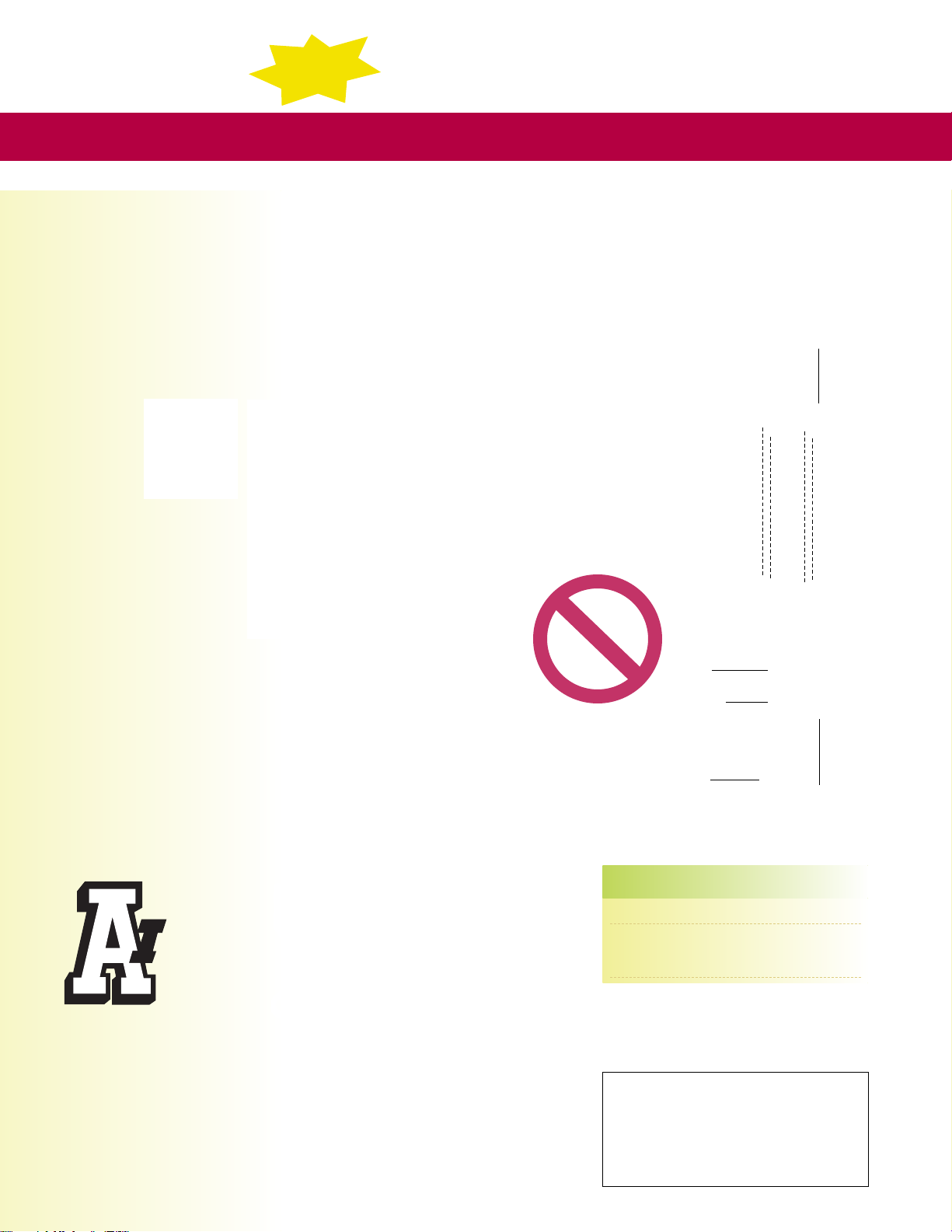
Easy Installation in Existing Walls
Components are not energized until the flexible cord is plugged in.
Do not plug in until all other wiring is complete.
1 Locate wall studs to position TV Bridge™ between studs.
2 Position the upper box behind (or close to) the installed TV
bracket. Position lower box within 3-1/2 ft. of the existing
receptacle or power conditioner that will power the installation.
Install upper box and lower box in the same stud cavity.
3 Pull a length of NM cable long enough to reach both boxes. Pull
low voltage, coaxial, speaker wires, etc. before installing the boxes.
4 Install NM
cable
through
the
installed
cable
connector.
Attach the boxes securely to the
wall by tightening the two wing
screws.
5 Wire the duplex receptacle and
install it in the upper box.
6 Install LPCG50W cord grip onto
the flexible cord, then install
into the KD4550 using supplied locknut.
7 Connect the cord conductors to corresponding conductors of NM cable
installed in the lower box. Install wire nuts.
8 Install KD4550 assembly to the lower box. Mount the CED13 cable
entry device or CED1 entrance hood to the low voltage sides of both
boxes (machine screws supplied).
9 Install cover plates.
10 Connect TV power cable to the installed duplex outlet
in the upper box Make low voltage connections.
C
Flat
screen
TV
No messy
wires running
down the wall
Wires stay
hidden behind
wall
KD4550
LPCG50W
Flexible
cord
CED1
CED13
Arlington
1 Stauffer Industrial Park
Scranton, PA 18517
800/233.4717
Fax 570/562.0646
www.aifittings.com
www.arlnew.com
www.arlingtonlowvoltage.com
©2010 Arlington Industries, Inc.
Note:
- This product is not designed to be an extension
of a structure’s hard wiring.
- Components are not energized until the flexible
cord is plugged in. Do not plug in until all other
wiring is complete.
Patents pending
TVBR2505K 0410/15M
CATALOG UPC/DCI/NAED DESCRIPTION UN IT/STD
NUMBER MFG #01 8997 PKG
TVBR2505K 09658 TV Bridge™ 1
TVBR2505KGC 09108 TV Bridge™ 1
with ground clip
(for Canada)
Includes (2) recessed boxes with trim plates and installed NM
cable connectors, (2) duplex covers, wire nuts, tamper-resistant
duplex receptacle, installation screws, LPCG50W cord grip,
4 ft. cord, KD4550 and The SCOOP™ (2) CED1 entrance
hoods, (2) CED13 cable entry devices.
Distributed by
 Loading...