

Page 1
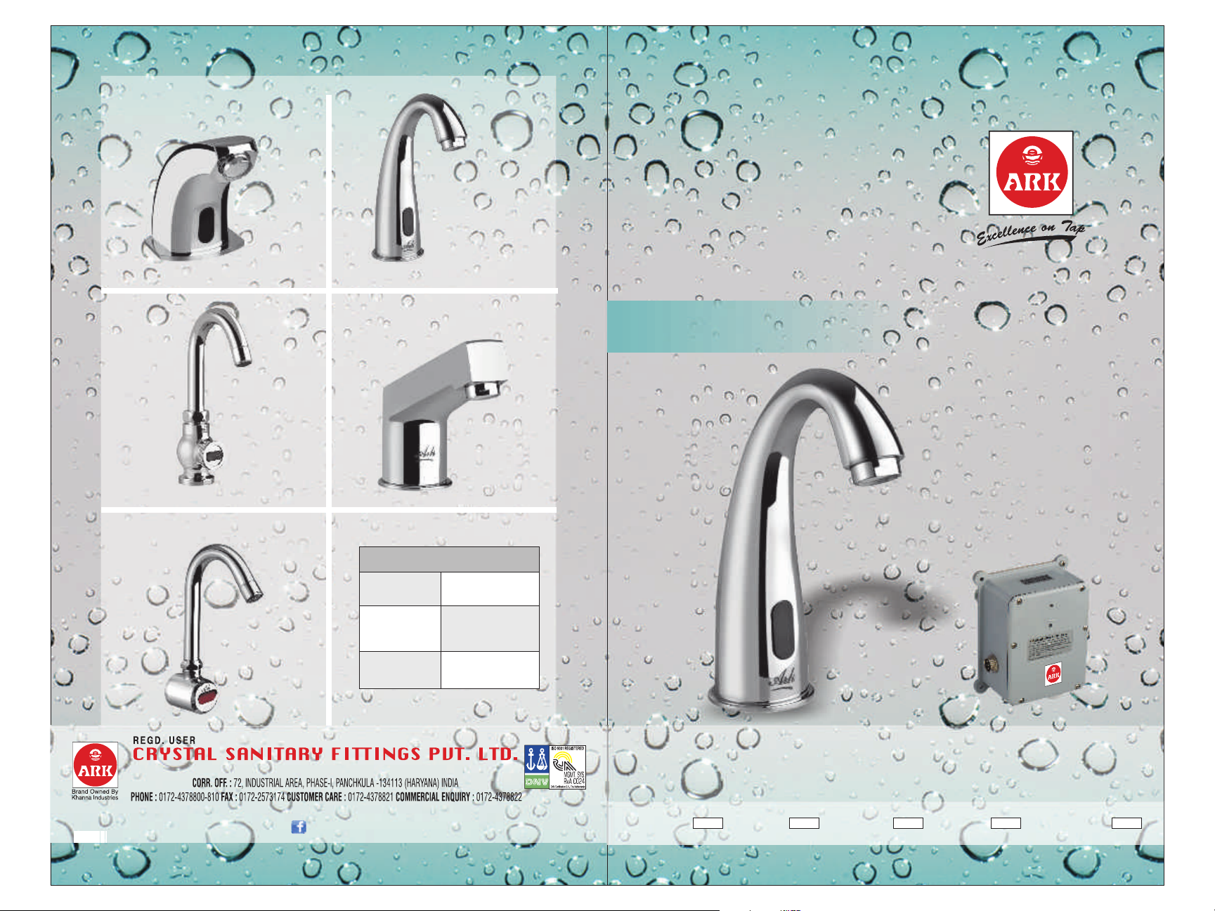
PENGUIN
HERON
PELICAN
FLAMINGO
71005
71005B
71005E
71001
PLOVER
ABOUT CAT NO.
No Suffix
B
71006
71006B
71006E
USER GUIDE
71007
71007B
71007E
Both
AC & DC
Only DC
(Batteries)
Only AC
(Electricity)
61004
61004B
61004E
E
An ISO 9001 : 2008 Certified Company
E-MAIL : [email protected] WEBSITE : www.crystalfaucets.com, www.crystalbathfittings.com, www.crystalsanitaryfittings.in
Like us on www.facebook.com/crystalsanitaryfittings
8
SENSOR TAP
Pillar Sensor Taps & Bib Sensor Tap
HERON PLOVER
PELICANPENGUIN
FLAMINGO
Page 2
ABOUT SENSOR TAPS
SPECIFICATIONS
Ark Sensor Taps are automatic faucets through which water flows only
when hands activate the fixture. These taps have built in infrared sensors
which sense the presense of an object i.e. user's hands in front of the tap
and sends signal to a solenoid valve to open. The flow automatically gets
terminated after a few seconds when the object is no longer present.
HISTORY
Automatic faucets were first developed in the 1950s but produced
commercially in the late 1980s. These have now become common in
developed countries. These save upto 70% water consumption.
BENEFITS
Water Saving
suitable for public places i.e. public washrooms, particularly at
airports and hotels where they help reduce water consumption.
- Other than private residences, are also
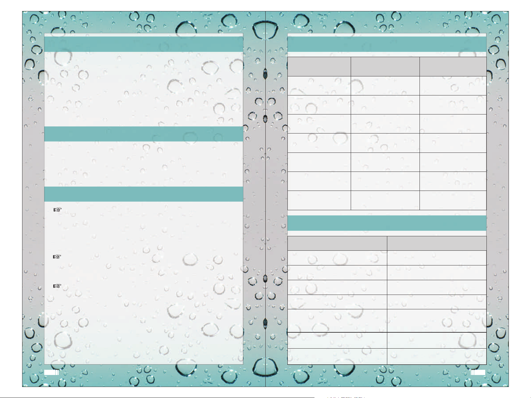
SPECIFICATIONS PILLAR TAP SENSORS BIB TAP SENSORS
Power Consumption
Input Voltage
No. Of Batteries
Size of control box
unit
Life of Batteries
Models AC & DC/Only AC/
Sensor Type
2-5 Watts
220 V AC/ 6V DC
4 x AA size Alkaline
110x60x130 mm 110x60x130 mm
Approx.25000 Cycles Approx.25000 Cycles
Only DC
Infra-Red Sensor
2-5 Watts
220 V AC/ 6V DC
4 x AA size Alkaline
AC & DC/Only AC/
Only DC
Infra-Red Sensor
COMPOSITION
Pillar Tap Sensor Bib Tap Sensor
Hygienic
diseases is reduced.
Cost Saving
for conservationists but also for the budget-conscious, sensors
can be seen as an investment as they pay for themselves with
reduced water consumption and maintenance costs.
Our Sensor Taps models have the possibility to be powered by regular
AA batteries (Alkaline) or by mains 220 V AC via a 6V transformer or Both.
- As there are no points of contact transmission of
- As excess water use is no longer an issue solely
2
Pillar Tap Body with 6 Pin Wire &
PVC Pipe
Control Box with Solenoid Valve
Installation & Troubleshooting
Guide
Screw with PVC Sleeve (4 Pcs)
4 * AA' Size Duracell Alkaline
batteries (In models AC&DC
and Only DC)
Check Nut
Connector
Bib Tap Body with 6 Pin Wire
Control Box with Solenoid Valve
Installation & Troubleshooting
Guide
Screw with PVC Sleeve (4 Pcs)
4 * AA' Size Duracell Alkaline
batteries (In models AC&DC
and Only DC)
3
Page 3
BIB SENSOR PILLAR SENSOR
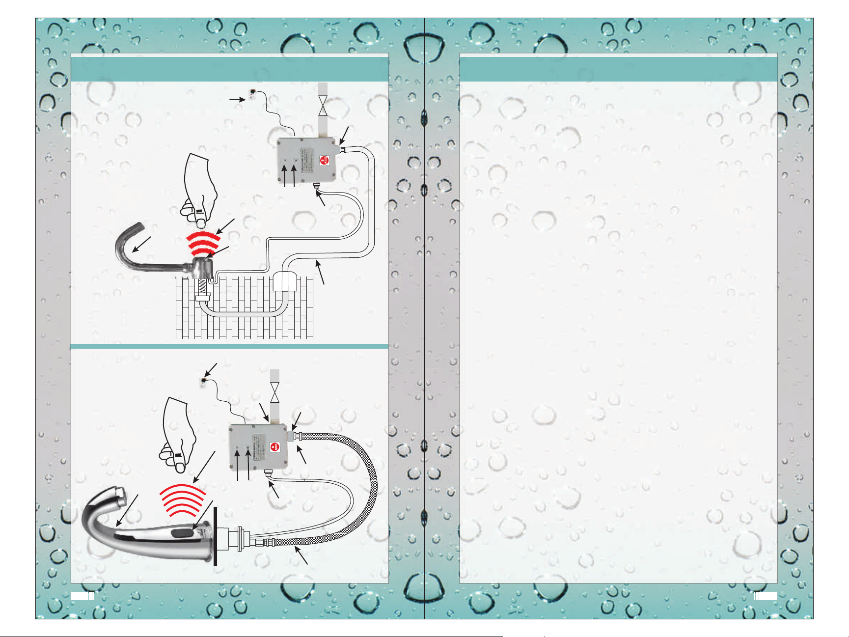
INSTALLATION DIAGRAM
SUPPLY
BIB SENSOR TAP
ELECTRICAL
INFRARED RAYS
SENSOR
INFRARED
CONTROL
WATER
BOX
LED
INDICATOR
DISTANCE
INLET
SCREW
6 PIN
ADJUSTMENT
WATER
V1
WATER
WITH WIRE
CONNECTOR
PIPELINE
½ Inch
OUTLET
INSTALLATION PROCEDURE
Please refer to the diagram:
Pillar Tap Sensors: (Fig. 1)
Install the Pillar Tap on the Wash Basin and tighten the Check
?
Nut.
?
Fix the connector on PVC pipe loose end.
?
Fix the other end of this Connector to the Control Box.
Bib Tap Sensors:
?
Fix Bib Tap Body on the wall socket of 1/2" Pipe Line .
?
Connect the other end of this 1/2" pipe line to the outlet of the
Control Box. Ensure that the control box is mounted vertically
as shown in fig. 2.
CONTROL BOX INSTALLATION PROCEDURE:
For AC & DC and DC Models only:
?
Loosen the Control Box cover plate screws ( 6 Nos.)
(Fig. 2)
(Only in AC & DC or DC models)
PILLAR SENSOR TAP
SUPPLY
ELECTRICAL
INFRARED RAYS
SENSOR
INFRARED
LED
INLET
WATER
DISTANCE
INDICATOR
ADJUSTMENT
SCREW
V1
6 PIN
CONNECTOR
CONNECTOR
WATER
OUTLET
WITH WIRE
?
Remove the cover plate and insert AA size Alkaline Batteries
( 4 Nos.) inside theBattery Box.
?
Tighten the control box screws.
?
Fix the control box on the wall (Near or Below the tap).
Common for All Models :
?
Connect the water supply through valve V1 or Angle Valve and
then connect the pipe at inlet of Control Box.
?
Connect the 6 Pin Wire (from Pillar/Bib tap) to the Control Box
?
Connect the 3 pin plug to main supply only in case of AC/DC
and AC Models.
FLEXIBLE
PIPE
Fig. 1 Fig. 2
The Sensor Tap is now ready to work.
4 5
5
Page 4
IMPORTANT INFORMATION & GUIDELINES
TROUBLESHOOTING
1. Duracell Alkaline 'AA' size batteries should be used for DC
Models.
2. The Control Box should be fixed vertically as shown in
diagram.
3. Provide a Stop Valve on the inlet line of Control Box.
4. Unplug the Power Cable/ Remove Batteries if the sensor tap is
not in use for longer periods.
5. Ideal Sensing distance is 15 Cm which is pre fixed in the
Sensor (All Models).
6. The sensing distance can be also adjusted with the help of the
Distance Adjusting screw provided on the cover plate.( To be
touched only if required)
7. Make provision of a 3 Pin socket near the Control Box ( For
AC/DC and AC Models).
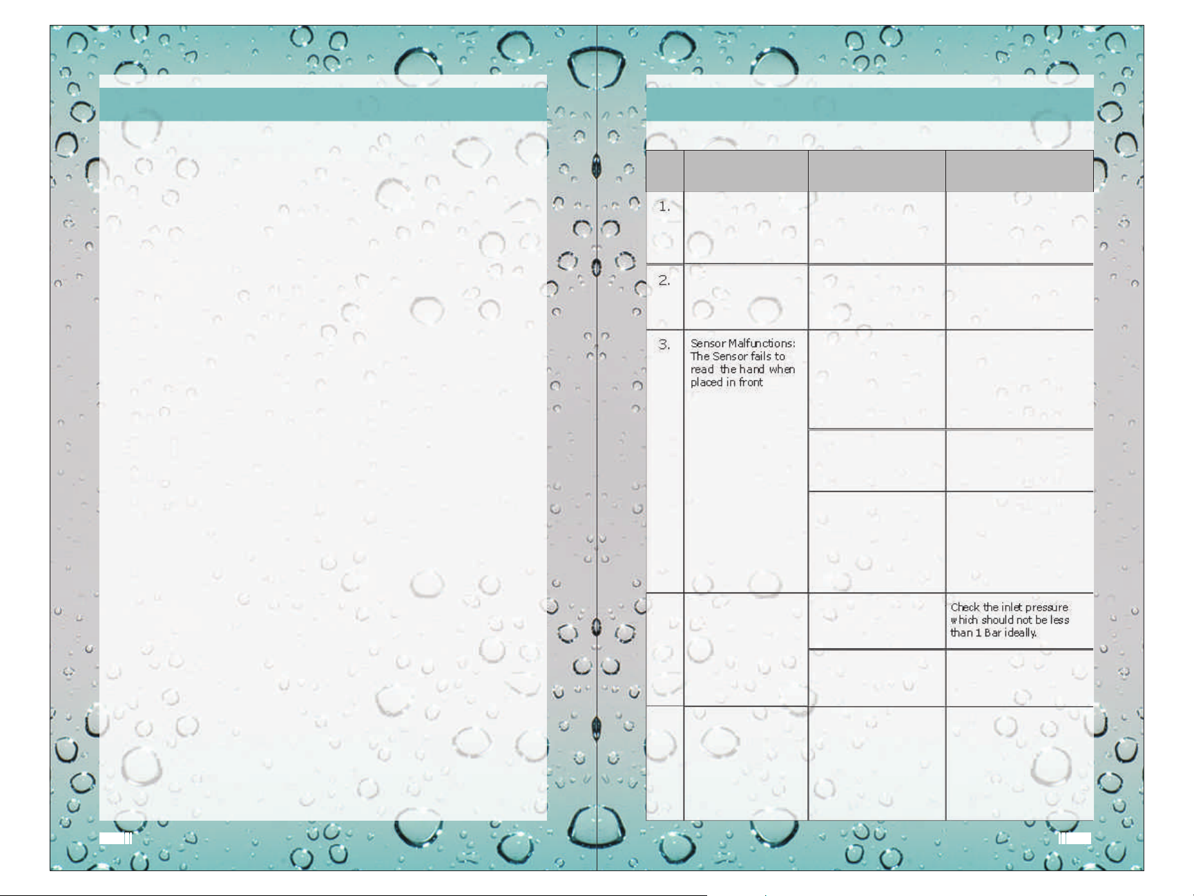
Sr.
No.
1.
2.
3.
4.
PROBLEM REASON ACTION
Sensor connected but
not working
Leakages
Sensor Malfunctions:
The Sensor fails to
read the hand when
placed in front
Improper Flow
Plug /Batteries not
properly inserted.
Old Batteries
Worn out Rubber
Washers/Seal or loose
joints
Batteries have not been
inserted properly in the
Battery Box in case of
AC/DC and DC Models
Sensor cable not plugged
properly
(In all Models).
Washbasin is big or small
in size due to which the
pre fixed sensing distance
of 15cm is not being
maintained.
Pressure is less than 1Bar.
Check the Plug /Batteries
and insert them properly.
Replace the Batteries.
Replace Sealing Washers/
Tighten Joints
Take out the batteries and
fix them properly .
Switch of the Power and
switch it on after waiting
for 10 seconds
Unplug the sensor cable
and fix it again
Reset sensing distance with
the help of the adjustment
screw on the cover plate as
shown in figure by carefully
rotating the adjustment
screw with help of a Screw
Driver.
Check the inlet pressure
which should not be less
than 1 Bar ideally.
8. Ideal inlet Water pressure required is 1 Bar - 5 Bars (Max.)
9. The AC/DC model can operate either on Mains or Batteries.
In case of a power cut it automatically switches to battery.
6
Continuous Water
5.
Flow
The Pillar/Bib Tap Aerator
is clogged.
Problem in the Solenoid
Valve which is damaged
or dust particles
deposited on the valve
seat
7
Remove Aerator and clean it.
Shut the power Off and On
a couple of times in intervals
of 10 Seconds
Check the Solenoid Valve
repair/replace it.
7
 Loading...