


2017 Street Owner's
Manual
99472-17
Thu May 05 21:52:19 CDT 2016

NOTES

TABLE OF CONTENTS
INTRODUCTION
Your Owner's Manual.........................................................1
Customer Service Assistance............................................1
SAFETY FIRST
Safety Definitions...............................................................3
Rules of the Road..............................................................3
Safety: Operating Rules.....................................................4
Harley-Davidson Motorcycles Are for On-Road Use
Only............................................................................4
General.......................................................................4
Operation....................................................................5
Stability, Steering and Handling..................................6
Cargo and Loading.....................................................8
Tires............................................................................8
Towing and Trailering..................................................9
Fuel and Exhaust........................................................9
Cooling System.........................................................10
Brakes.......................................................................11
Battery......................................................................11
Hazardous Materials.................................................12
Maintenance.............................................................12
Parts and Accessories..............................................13
Labels..............................................................................13
YOUR MOTORCYCLE
Vehicle Identification Number (VIN).................................17
General.....................................................................17
Location....................................................................17
Abbreviated VIN........................................................17
Primary Controls and Ser vice Components.....................21
SECURITY SYSTEM
Security System...............................................................25
Components.............................................................25
Options.....................................................................25
Security Status Indicator..................................................25
Arming and Disarming.....................................................25
Armed.......................................................................25
Disarmed..................................................................26
Alarm................................................................................26
Warnings...................................................................26
Alarm Activation........................................................26
Alarm Deactivation....................................................27
Personal Identification Number (PIN)...............................27
Disarming with a PIN................................................27
Changing the PIN.....................................................28
i

TABLE OF CONTENTS
Security System Fob........................................................29
Assigning Fob ..........................................................29
Fob Battery...............................................................30
Riding with a Fob......................................................31
Riding without a Fob.................................................31
Transport Mode................................................................32
To Enter Transport Mode...........................................32
To Exit Transport Mode.............................................32
Storage and Service Departments...................................32
Long-Term Parking...................................................32
Service Departments................................................32
Siren (If Equipped)...........................................................32
Chirp Mode...............................................................32
Chirpless Mode.........................................................32
Switching Modes.......................................................33
Disconnecting Power................................................33
Troubleshooting................................................................33
Security Lamp...........................................................33
Fob............................................................................33
Siren (If equipped)....................................................34
BEFORE RIDING
Removing Motorcycle from Storage.................................35
Pre-Ride Checklist...........................................................35
Break-In Riding Rules......................................................36
The First 800 Kilometers (500 Miles)........................36
Filling the Fuel Tank.........................................................36
Removing Fuel Filler Cap.........................................37
Installing Fuel Filler Cap...........................................37
Fuel System Information..................................................38
Gasoline....................................................................38
Catalytic Converter...................................................39
Adjusting Mirrors..............................................................40
Operating Jiffy Stand.......................................................40
Location....................................................................40
Jiffy Stand Switch: International Models...................40
Adjusting Shock Absorbers..............................................40
General.....................................................................40
Adjustment................................................................41
OPERATION
Controls, Instruments and Switches................................43
Clutch Hand Lever....................................................43
Gear Shift Lever........................................................43
Left-Hand Control Module.........................................43
Speedometer/Odometer...........................................44
Right-Hand Control Module......................................44
Brakes.......................................................................44
ii

TABLE OF CONTENTS
Throttle Twist Grip.....................................................44
Ignition Switch...........................................................44
Fork Lock..................................................................45
Instruments......................................................................46
Speedometer............................................................46
Gear/Tachometer......................................................47
Odometer: Mileage, Trip A, Tr ip B.............................47
Odometer Messages................................................48
Clock.........................................................................49
Left Hand Control Switches.............................................50
High Beam................................................................50
Low Beam.................................................................50
Left Turn....................................................................50
Right Turn..................................................................51
Horn..........................................................................51
Right Hand Control Switches...........................................52
Off.............................................................................52
Run...........................................................................52
Start..........................................................................52
Anti-lock Brake System (ABS).........................................53
Identification..............................................................53
Brake System...................................................................54
Front Brake Lever......................................................54
Rear Brake Pedal......................................................54
Non-ABS Brake System............................................54
Anti-lock Brake System (ABS)..................................55
How ABS Works........................................................55
How To Use ABS.......................................................55
ABS: Tires and Wheels.............................................56
Indicators.........................................................................58
Starting the Engine..........................................................60
Starting after Tipover........................................................61
Shifting Gears..................................................................61
Finding Neutral.........................................................61
Starting from a Stop..................................................61
Upshift (Acceleration)...............................................62
Downshift (Deceleration)...........................................63
Stopping the Engine.........................................................64
AFTER RIDING
Storing Motorcycle...........................................................65
Cleaning and General Care.............................................65
Cleaning Wheels and Tires.......................................67
Radiator....................................................................67
Recommended Cleaning Products..................................67
Washing the Motorcycle...................................................73
Preparation...............................................................74
Cleaning Wheels and Tires.......................................74
iii

TABLE OF CONTENTS
Washing the Motorcycle............................................74
Drying the Motorcycle...............................................75
Polishing and Sealing...............................................75
Leather and Vinyl Care....................................................75
Denim Finish....................................................................76
Cleaning Denim Finish..............................................76
SCHEDULED MAINTENANCE
Maintenance....................................................................77
Preparing the Motorcycle for Maintenance......................77
Setting Motorcycle Upright........................................77
Changing Engine Oil and Filter........................................78
Checking Engine Oil Level...............................................80
Oil Level Cold Check.................................................80
Oil Level Hot Check..................................................81
Checking Pressure and Inspecting Tires..........................81
Inspecting Brake Pads and Discs....................................82
Brake Pads...............................................................82
Brake Disc ................................................................83
Checking Systems for Leaks or Abrasions......................83
Checking Brake Fluid Le vel and Changing Brake Fluid....83
Checking Brake Fluid Level......................................84
Changing Brake Fluid...............................................85
Checking and Adjusting Throttle Cables..........................85
Checking Clutch and Brake Controls...............................86
Clutch Hand Lever....................................................86
Brake Hand Lever.....................................................86
Miscellaneous Lubrication................................................86
Maintaining Front For k ....................................................86
Adjusting Steering Head Bearings...................................87
Cleaning Radiator............................................................87
Coolant.............................................................................88
General.....................................................................88
Checking Coolant Level............................................89
Replacing Coolant............................................................89
Inspecting Rear Fork Bearing..........................................89
Checking Drive Belt and Sprockets..................................90
Inspecting Rear Shock Bushing.......................................92
Checking for Exhaust Leaks............................................92
Inspecting Air Filter..........................................................92
Lubricating Fuel Cap Lock...............................................93
Inspecting Valve Lash......................................................93
Cleaning Battery..............................................................93
Replacing Spark Plugs.....................................................93
Checking Electrical Equipment and Switches..................95
SERVICE PROCEDURES
Tires.................................................................................97
iv

TABLE OF CONTENTS
General Information..................................................97
Inspecting Tires.........................................................97
Replacing Tires.........................................................99
Lubrication.....................................................................100
Engine Lubrication..................................................100
Low Temperature Lubrication..................................101
Battery Maintenance......................................................102
Battery Safety.........................................................102
Cleaning and Inspecting.........................................102
Storing the Battery..................................................103
Charging Battery.....................................................103
Absorbed Glass Mat (AGM) Battery Charging
Information..............................................................104
Voltage Test.............................................................105
Battery Tender Connector..............................................105
Battery Replacement.....................................................106
Removing the Battery.............................................106
Installing Battery.....................................................110
Fuses and Relays..........................................................111
Main Fuse...............................................................111
Replacing Fuses.....................................................112
Relays.....................................................................113
Side Covers....................................................................114
Headlamp.......................................................................115
Checking Headlamp Alignment...............................115
Adjusting Headlamp................................................116
Replacing Headlamp or Position Bulb....................118
Tail Lamp........................................................................120
Replacing Tail Lamp Bulb.......................................120
Turn Signal Bulb.............................................................120
Replacing Turn Signal Bulb.....................................120
Seat................................................................................121
Removing Seat.......................................................121
Installing Seat.........................................................121
Noise Control System....................................................122
Tampering...............................................................122
SPECIFICATIONS
Specifications.................................................................123
Tires........................................................................123
Weights and Dimensions........................................124
Capacities...............................................................126
Engine and Transmission........................................126
Electrical.................................................................127
TROUBLESHOOTING
Troubleshooting: General...............................................129
Engine............................................................................129
v

TABLE OF CONTENTS
Starter Does Not Operate or Does Not Turn Engine
Over........................................................................129
Engine Turns Over But Does Not Start...................129
Starts Hard.............................................................129
Starts But Runs Irregularly or Misses.....................130
A Spark Plug Fouls Repeatedly..............................130
Pre-ignition or Detonation (Knocks or Pings)..........130
Overheats...............................................................130
Excessive Vibration.................................................130
Engine Oil Not Circulating (Oil Pressure Lamp Lit)..130
Cooling System..............................................................131
Overheats...............................................................131
Electrical System...........................................................131
Alternator Does Not Charge...................................131
Alternator Charge Rate is Below Normal................131
Transmission..................................................................131
Transmission Shifts Hard........................................131
Transmission Jumps Out of Gear............................131
Clutch Slips.............................................................131
Clutch Drags or Does Not Release.........................132
Clutch Chatters.......................................................132
Brakes............................................................................132
Brakes Do Not Hold Normally.................................132
WARRANTIES
General Warranty Information........................................133
Keeping it All Harley-Davidson...............................133
California and Select International Markets Evaporative
Emission Controls: 2017 Models....................................134
EPA Noise Regulations in the United States..................134
EPA Regulations.....................................................134
Warranty/Service Information.........................................134
Reporting Safety Defects in the United States...............135
NHTSA Statement..................................................135
Required Documentation for Imported Motorcycles.......135
Owner Contact Information............................................135
Questions and Concerns...............................................136
2017 Harley-Davidson Motorcycle Limited Warranty.....137
24 Months/Unlimited Miles......................................137
Duration..................................................................138
Owner's Obligations................................................138
Exclusions...............................................................138
Other Limitations.....................................................139
Important: Read Carefully.......................................140
2017 Australia/New Zealand Harley-Davidson Motorcycle
Manufacturer's Limited Warranty....................................141
24 Months/Unlimited Miles......................................141
Your Consumer Rights............................................141
vi

TABLE OF CONTENTS
Warranty.................................................................141
Warranty Period......................................................142
Obtaining Warranty Ser vice....................................142
Exclusions...............................................................142
Other Limitations.....................................................143
Important: Read Carefully.......................................144
2017 Harley-Davidson Motorcycle Noise Control System
Limited Warranty............................................................144
Other Rights............................................................146
Recommendations for Required Maintenance........146
2017 Harley-Davidson Emission Control System Limited
Warranty.........................................................................146
Items Covered by this Emission Warranty .............148
Other Rights............................................................148
Recommendations for Required Maintenance........149
California Emissions Control Warranty Statement.........149
Your Warranty Rights and Obligations....................149
Manufacturer's Warranty Coverage.........................149
Owner's Warranty Responsibilities..........................149
Additional Warranty Terms......................................150
What Is Covered by this Emission Warranty...........152
What Is Not Covered by this Emission Warranty.....152
SERVICE INTERVALS AND RECORDS
Service Records.............................................................155
Regular Service Intervals........................................155
Maintenance Records.............................................159
Service Literature...........................................................162
TRADEMARKS
H-D U.S.A., LLC Trademark Information........................165
Product Registered Marks.............................................166
vii

TABLE OF CONTENTS
viii

YOUR OWNER'S MANUAL
This manual has been prepared to acquaint you with the
operation, care and maintenance of your motorcycle. It also
provides important safety information. F ollow these instructions
carefully for maximum motorcycle performance and for your
personal motorcycling safety and pleasure.
Your owner's manual contains instructions for operation and
minor maintenance. Major repairs are covered in the HarleyDavidson service manual. Major repairs require the attention
of a skilled technician and the use of special tools and equipment. Your Harley-Davidson dealer has the facilities, experience and Genuine Harley-Davidson parts necessary to render
this valuable service.We recommend that any emission system
maintenance be performed by an authorized Harley-Davidson
dealer.
Harley-Davidson reserves the right to change specifications,
equipment or designs at any time without notice and without
incurring obligation.
This owner's manual should be considered a permanent part
of the motorcycle and should remain with the motorcycle if it
is resold.
CUSTOMER SERVICE ASSISTANCE
Most sales or service issues are resolved at the dealership.
1. Discuss your problem with the appropriate personnel at
the dealership in the Sales, Service or Parts area. If that
proves unsuccessful, speak to the owner of the dealership
or the general manager.
2. If you cannot resolve the issue with the dealership , contact
the Harley-Davidson Customer Support Center.
Harley-Davidson Motor Company
Attention: Harley-Davidson Customer Support Center
P.O. Box 653
Milwaukee, Wisconsin 53201
1-800-258-2464 (U.S. only)
1-414-343-4056
For customers outside the US, contact your local Harle y-Davidson market office, call 1-414-343-4056 or visit harley-davidson.com.
INTRODUCTION
1

Date of Purchase:
x
Table 1. Vehicle and Personal Data
DEALER INFORMATIONPERSONAL INFORMATION
Name:Name:
x x
Address:Address:
x x
Address:Address:
x x
Sales Contact:Vehicle Identification Number:
x x
Service Contact:Key Number:
x x
2 Introduction

SAFETY DEFINITIONS
Statements in this manual preceded by the following words
are of special significance:
WARNING indicates a potentially hazardous situation
which, if not avoided, could result in death or serious
injury. (00119a)
CAUTION indicates a potentially hazardous situation
which, if not avoided, may result in minor or moderate
injury. (00139a)
NOTICE indicates a potentially hazar dous situation which,
if not avoided, may result in property damage. (00140b)
NOTE
Refers to important information and is placed in italic type. It
is recommended that you take special notice of these items.
RULES OF THE ROAD
• Always sound your horn, use your turn signals and exercise caution when passing other vehicles going in the
same direction. Never pass going in the same direction
at street intersections, on curves or when going up or down
a hill.
• At street intersections, give the right-of-way. Do not presume you have the right-of-way, as the other driver may
not know that it is your turn.
• Always signal when preparing to stop, turn or pass.
• Promptly obey all traffic signs, including those signs used
for the control of traffic at intersections. Alw ays obe y traffic
signs near schools and at railroad crossings.
• When intending to turn, signal at least 30.5 m (100 ft)
before reaching the turning point. If turning across an
intersection, move over to the centerline of the street
(unless local rules require otherwise). Slow down when
entering the intersection and turn carefully.
• Never anticipate a traffic light.When a change is indicated
from GO to STOP (or STOP to GO), slow down and wait
SAFETY FIRST
3

for the light to change. Never run through a yellow or red
traffic light.
• While turning, watch for pedestrians, animals, as well as
vehicles.
• Do not leave the curb or parking area without signaling.
Make sure that your way is clear to enter moving traffic.
A moving line of traffic always has the right-of-way.
• Make sure that your license plate is installed in the position
specified by law. Make sure that your license plate is
always clearly visible. Keep the license plate clean.
• Ride at a safe speed that is consistent with the type of
highway you are on. Pay strict attention to whether the
road is dry, oily, icy or wet.
• Watch for debris such as leaves or loose gravel.
• Weather and traffic conditions on the highway dictate
adjusting your speed and driving habits accordingly.
SAFETY: OPERATING RULES
Harley-Davidson Motorcycles Are for On-Road
Use Only
This motorcycle is not equipped with a spark arrester. This
motorcycle is designed to be used only on the road. Operation
or off-road usage in some areas may be illegal. Obey local
laws and regulations.
General
Consult a Harley-Davidson dealer regarding any questions
or problems that occur in the operation of your motor cycle.
Failure to do so can aggravate an initial problem, cause
costly repairs, cause an accident and could result in death
or serious injury. (00020a)
• Make sure all equipment required by federal, state and
local law is installed and in good operating condition.
• Know and respect the rules of the road. Read the safety
information that is provided by your state or regional traffic
authority.
• In the United States, read the RIDING TIPS booklet that
is provided with this owner's manual. Read the MOTORCYCLE HANDBOOK which is made available by your
state or regional traffic authority.
• Protect your motorcycle against theft. Lock the front fork.
Remove the key when parking your motorcycle.
4 Safety First
Do not add sidecar to this motorcycle. Operating motorcycle with sidecar can cause loss of vehicle control, which
could result in death or serious injury. (00590d)
Operation
Before operating your new motorcycle, it is your responsibility
to read and follow the operating and maintenance instructions
in this manual and follow these rules for your personal safety.
Motorcycles are different from other vehicles. They
operate, steer, handle and brake differently. Unskilled or
improper use could result in loss of control, death or serious injury. (00556c)
• Take a rider training course.
• Read all the owner's manual before riding, adding
accessories or servicing.
• Wear an approved helmet, clothing and foot gear suited
for motorcycle riding. Br ight or light colors are best for
greater visibility in traffic, especially at night. Avoid loose,
flowing garments and scarves.
• Never tow a trailer.
• Before starting the engine, review the BEFORE RIDING,
Pre-Ride Checklist.
Striking an object, such as a curb or pothole can cause
internal tire damage. If an object is struck, have the tire
inspected immediately inside and out by a Harley-Davidson
dealer. A damaged tire can fail while riding and adversely
affect stability and handling, which could result in death
or serious injury. (00058b)
Travel at speeds appropriate for road and conditions and
never travel faster than posted speed limit. Excessive
speed can cause loss of vehicle control, which could result
in death or serious injury. (00008a)
• Do not exceed the legal speed limit or drive too fast for
existing conditions. Always reduce speed when poor
driving conditions exist. High speed increases the influence
Safety First 5

of any other condition affecting stability and increases the
possibility of loss of control.
• Pay strict attention to road surfaces and wind conditions
and keep both hands on the handlebar grips at all times
when riding the motorcycle. An y two wheeled vehicle ma y
be subject to upsetting forces such as wind blasts from
passing trucks, holes in the pavement, rough road surfaces, rider control error, etc. These forces may influence
the handling characteristics of your motorcycle. If this
happens, reduce speed and guide the motorcycle with a
relaxed grip to a controlled condition. Do not brake abruptly
or force the handlebar. This may aggravate an unstable
condition.
• New riders should gain experience under various conditions while riding at moderate speeds.
• Operate your motorcycle defensively. In an accident, a
motorcycle does not afford the same protection as an
automobile.
• It is the rider's responsibility to instruct passengers on
proper riding procedures.
• Do not allow other individuals to operate the motorcycle
unless they are experienced, licensed riders and are
thoroughly familiar with the operation of the motorcycle.
Front and/or rear guard(s) can provide limited leg and
cosmetic vehicle protection under unique circumstances.
(Fall over while stopped, very slow speed slide .) It is not
made or intended to provide protection fr om bodily injury
in a collision with another vehicle or any other object.
(00022b)
Stability, Steering and Handling
Do not operate vehicle with forks locked. Locking the f orks
restricts the vehicle's turning ability, which could result
in death or serious injury. (00035a)
Regularly inspect shock absorbers and front f orks. Replace
leaking, damaged or worn parts that can adversely affect
stability and handling, which could result in death or serious injury. (00012a)
6 Safety First

Do not operate motorcycle with loose, worn or damaged
steering or suspension systems. Contact a Harley-Davidson dealer for repairs. Loose, worn or damaged steering
or suspension components can adversely affect stability
and handling, which could result in death or serious injury .
(00011a)
Do not open storage compartments while riding. Distractions while riding can lead to loss of control, which could
result in death or serious injury. (00082a)
When riding on wet roads, brake efficiency and traction
are greatly reduced. Failure to use care when braking,
accelerating or turning on wet roads can cause loss of
control, which could result in death or serious injury.
(00041a)
Safety First 7
Cargo and Loading
Do not exceed the motorcycle's Gross Vehicle Weight
Rating (GVWR) or Gross Axle Weight Rating (GAWR).
Exceeding these weight ratings can lead to component
failure and adversely affect stability , handling and performance, which could result in death or serious injury . (00016f)
• GVWR is the sum of the weight of the motorcycle,
accessories and the maximum weight of the rider, passenger and cargo that can be safely carried.
• The GVWR is shown on the information label, located on
the frame steering head or the frame downtube.
• GAWR is the maximum amount of weight that can be
safely carried on each end of the motorcycle.
• For GVWR and GAWR, front and rear, refer to Table 22
• Keep cargo weight concentrated close to the motorcycle
and as low as possible.
• Distribute weight evenly on both sides of the vehicle.
• Do not load bulky items too far behind the rider or add
weight to the handlebars or front forks.
• Do not exceed maximum specified load in each saddlebag
(if equipped).
• Luggage racks (if equipped) are designed for lightweight
items. Do not overload racks.
• Make sure cargo is secure. Make sure the cargo will not
shift while riding and check the cargo periodically.
Accessories that change the operator's riding position may
increase reaction time and affect handling of the motorcycle.
• Large surfaces such as fairings, windshields, backrests
and luggage racks (if equipped) can adversely affect on
stability and handling.
Tires
Be sure tires are properly inflated, balanced, undama ged,
and have adequate tread. Inspect y our tires regularly and
see a Harley-Davidson dealer for replacements. Riding
with excessively worn, unbalanced, improperly inflated,
overloaded or damaged tires can lead to tire failure and
adversely affect stability and handling, which could result
in death or serious injury. (00014b)
8 Safety First
Replace punctured or damaged tires. In some cases, small
punctures in the tread area may be repaired from within
the removed tire by a Harley-Davidson dealer. Speed
should NOT exceed 50 mph (80 km/h) f or the first 24 hours
after repair, and the repaired tire should NEVER be used
over 80 mph (130 km/h). Failure to follow this warning
could lead to tire failure and result in death or serious
injury. (00015b)
Towing and Trailering
Do not pull a trailer with a motorcycle. Pulling a trailer can
cause tire overload, damage and failure, reduced braking
performance, and adversely affect stability and handling,
which could result in death or serious injury. (00018c)
Do not tow a disabled motorcycle . Towing can adversely
affect stability and handling, which could result in death
or serious injury. (00017a)
Never tow a trailer.
Fuel and Exhaust
Stop the engine when refueling or servicing the fuel
system. Do not smoke or allow open flame or sparks near
gasoline. Gasoline is extremely flammable and highly
explosive, which could result in death or serious injury.
(00002a)
Avoid spills. Slowly remove filler cap. Do not fill above
bottom of filler neck insert, leaving air space for fuel
expansion. Secure filler cap after refueling. Gasoline is
extremely flammable and highly explosive, which could
result in death or serious injury. (00028a)
• Refuel in a well-ventilated area with the engine off.
• Remove the fuel filler cap slowly.
• Do not fill fuel tank above the bottom of the filler neck
insert. Leave air space to allow for fuel expansion.
Safety First 9
Avoid contact with exhaust system and wear protective
clothing that completely covers legs while riding. Exhaust
pipes and mufflers get very hot when engine is running
and remain too hot to touch, even after engine is turned
off. Failure to wear pr otective clothing could result in burns
or other serious injury. (00009a)
Do not run motorcycle in a closed gara ge or confined area.
Inhaling motorcycle exhaust, which contains poisonous
carbon monoxide gas, could result in death or serious
injury. (00005a)
Engine exhaust from this product contains chemicals
known to the State of California to cause cancer , and birth
defects or other reproductive harm. (00004f)
Cooling System
At operating temperature, radiators and oil coolers contain
hot fluids. Contact with a radiator or oil cooler can result
in minor or moderate burns. (00141b)
Coolant mixture contains toxic chemicals, which may be
fatal if swallowed. If swallowed, do not induce vomiting;
call a physician immediately . Use in a well ventilated area.
Irritation to skin or eyes can occur from vapors or direct
contact. In case of skin or eye contact, flush thoroughly
with water and go to hospital, if necessary. Dispose of
used coolant according to federal, state and local regulations. (00092a)
Cooling fans operate automatically , e ven when the ignition
switch is off. Keep hands away from fan blades. Contact
with a rotating fan blade can result in minor or moderate
injury. (00093a)
10 Safety First
Brakes
Battery
Brakes are a critical safety component. Contact a HarleyDavidson dealer for brake repair or replacement. Improperly serviced brakes can adversely affect brake performance, which could result in death or serious injury.
(00054a)
Apply front and rear brakes evenly. Favoring one brake
accelerates wear and reduces braking efficiency . Operation
with excessively worn brakes can lead to brake failure,
which could result in death or serious injury. (00135a)
Direct contact of D.O.T. 4 brake fluid with eyes can cause
irritation. Avoid eye contact. In case of eye contact flush
with large amounts of water and get medical attention.
Swallowing large amounts of D.O .T . 4 brake fluid can cause
digestive discomfort. If swallowed, obtain medical attention. Use in well ventilated area. KEEP OUT OF REACH OF
CHILDREN. (00240a)
Batteries, battery posts, terminals and related accessories
contain lead and lead compounds, and other chemicals
known to the State of California to cause cancer , and birth
defects or other reproductive harm. Wash hands after
handling. (00019e)
Batteries contain sulfuric acid, which could cause severe
burns to eyes and skin. Wear a protective face shield,
rubberized gloves and protective clothing when working
with batteries. KEEP BA TTERIES A W A Y FROM CHILDREN.
(00063a)
Safety First 11
It is possible to overload your vehicle's charging system
by adding too many electrical accessories. If the combined
electrical accessories operating at any one time consume
more electrical current than the vehicle's charging system
can produce, the electrical consumption can discharge
the battery and cause damage to the vehicle's electrical
system. See an authorized Harley-Davidson dealer for
advice about the amount of current consumed by additional electrical accessories or for necessary wiring
changes. (00211c)
Hazardous Materials
Prolonged or repeated contact with used motor oil may
be harmful to skin and could cause skin cancer. Pr omptl y
wash affected areas with soap and water. (00358b)
Maintenance
Perform the service and maintenance operations as
indicated in the regular service interval table. Lack of
regular maintenance at the recommended intervals can
affect the safe operation of your motorc ycle, which could
result in death or serious injury. (00010a)
• A new motorcycle must be operated according to the
special break-in procedure. See BEFORE RIDING, BreakIn Riding Rules.
• Proper care and maintenance, including tire pressure, tire
condition, tread depth and proper adjustment to steering
head bearings are important to stability and safe operation
of the motorcycle. Refer to Table 29.
12 Safety First
Parts and Accessories
Harley-Davidson parts and accessories are designed for
Harley-Davidson motorcyc les. Using non-Harley-Da vidson
parts or accessories can adversely affect performance,
stability or handling, which could result in death or serious
injury. (00001b)
• Use only Harley-Davidson approved parts and
accessories. Use of certain other manufacturer's perf ormance parts will void your new motorcycle warranty. See
your Harley-Davidson dealer for details.
Use Harley-Davidson replacement fasteners. Aftermarket
fasteners can adversely affect performance, which could
result in death or serious injury. (00013a)
• See your Harley-Davidson service manual for proper
torque values.
• Aftermarket fasteners may not have the specific property
requirements to perform properly.
See the Accessories and Cargo section in your owner's
manual. Improper car go loading or accessory installation
can cause component failure and adversely affect stability ,
handling and performance, which could result in death or
serious injury. (00021b)
• Harley-Davidson Motor Company cannot test and make
specific recommendations concerning every accessory or
combination of accessories sold.Therefore, the rider must
be responsible for safe operation of the motorcycle when
installing accessories or carrying additional weight.
• Additional electrical equipment may overload the electrical
system possibly resulting in electrical system and/or
component failure.
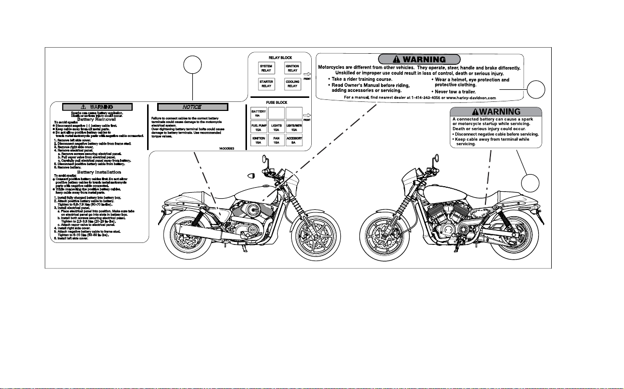
LABELS
See Figure 1 for safety and maintenance labels which were
on the vehicle when new. Refer to Table 2.
NOTE
Some labels are available in diff erent languages for destinations
outside the United States.
Safety First 13
Replacement labels can be purchased for your motorcycle. See a Harley-Davidson dealer.
3
1
2
om01644e
Figure 1. Labels
14 Safety First

Table 2. Labels
TEXTDESCRIPTIONPART NUMBERITEM
General warning29147-071
Battery warning15368-01A2
140011753
Battery
warning/Removal
and Installation
WARNING: Motorcycles are different from other vehicles.They operate, steer,
handle and brake differently. Unskilled or improper use could result in loss of
control, death or serious injury.
• Take a rider training course.
• Read Owner's Manual before riding, adding accessories or servicing.
• Wear a helmet, eye protection and protective clothing.
• Never tow a trailer.
For a manual, find nearest dealer at 1-414-343-4056 or www .harley-davidson.com
WARNING: A connected battery can cause a spark or motorcycle startup while
servicing. Death or serious injury could occur.
• Disconnect negative cable before servicing.
• Keep cable away from terminal while servicing.
WARNING: Sparks can cause battery explosion. Death or serious injury could
occur.To avoid sparks:
• Disconnect negative cable first.
• Keep cable away all metal parts.
• Do not allow positive battery cable to touch metal motorcycle parts with neg-
ative cable connected.
Safety First 15

NOTES
16 Safety First
VEHICLE IDENTIFICATION NUMBER (VIN)
2
1
om02126
General
A unique 17-digit serial or Vehicle Identification Number (VIN)
is assigned to each motorcycle. Refer to Table 3.
Location
See Figure 2.The full 17-digit VIN is stamped (1) on the right
side of the frame near the steering head. In some destinations,
a printed VIN label (2) is also attached on the front downtube.
Abbreviated VIN
The abbreviated VIN shows the vehicle model, engine type,
model year and sequential number. The abbreviated VIN is
stamped on the left side of the crankcase between the engine
cylinders.
Always give the full 17-digit Vehicle Identification Number when
ordering parts or making any inquiry about your motorcycle.
NOTE
1. Stamped VIN
2. VIN label
Figure 2.VIN Locations
YOUR MOTORCYCLE
17
1HD 4 NA A 1 3 H C 555000
1
2 3
4
5 6
7
8
9
om01842b
Figure 3.Typical Harley-Davidson VIN: 2017 Street Models
18 Your Motorcycle
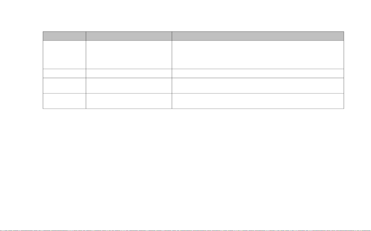
Table 3. Harley-Davidson VIN Breakdown: 2017 Street Models
POSSIBLE VALUESDESCRIPTIONPOSITION
1HD=Originally manufactured in the United StatesWorld manufacturer identifier1
5HD=Originally manufactured in the United States for sale outside the
United States
MEG=Originally manufactured in India
4=Middleweight motorcycle (351 cm3 to 900 cm3)Motorcycle type2
NA=XG500Model3
NB=XG750
A=Revolution XTM 500 cm3 liquid-cooled, fuel-injectedEngine type4
B=Revolution XTM 750 cm3 liquid-cooled, fuel-injected
Your Motorcycle 19
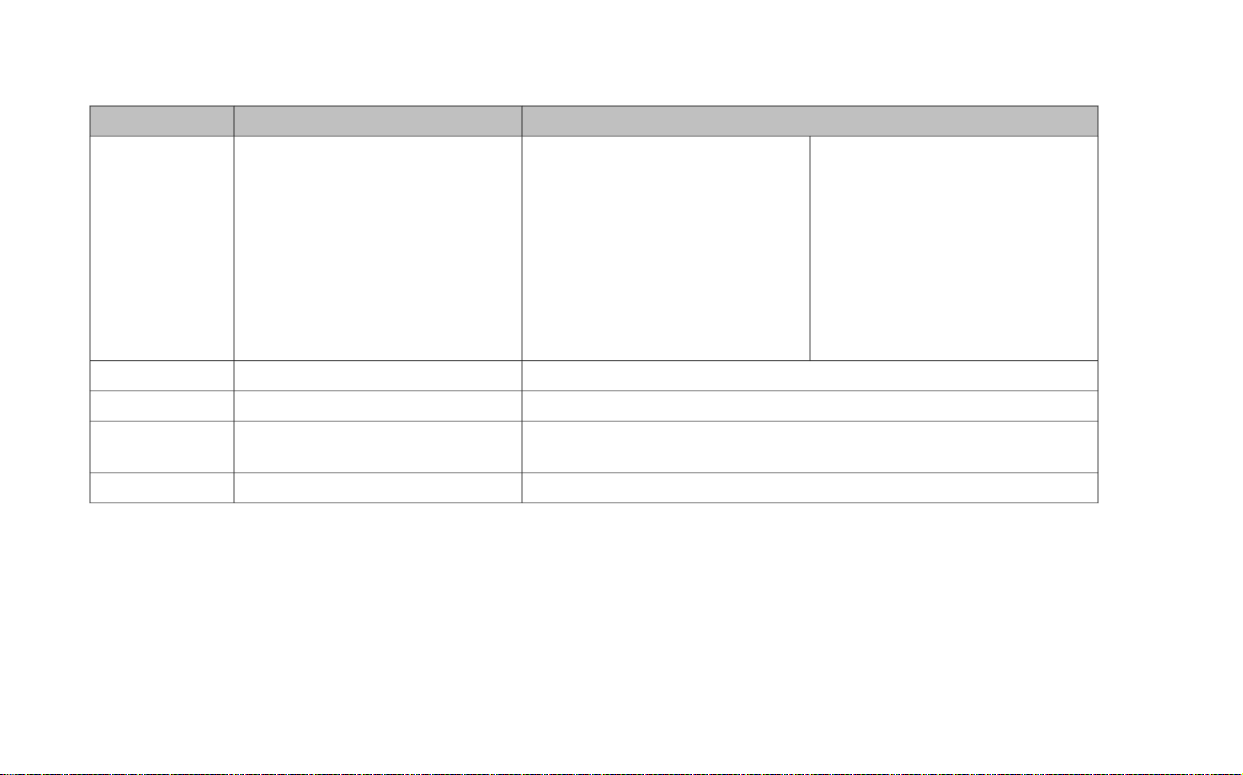
Table 3. Harley-Davidson VIN Breakdown: 2017 Street Models
POSSIBLE VALUESDESCRIPTIONPOSITION
5
tion
Can be 0-9 or XVIN check digit6
H=2017Model year7
C=Kansas City, MO U.S.A.Assembly plant8
N=Haryana India (Bawal District Rewari)
VariesSequential number9
Mid-year or Special IntroductionNormal IntroductionConfiguration/calibration, introduc2, 4=Domestic (DOM)1=Domestic (DOM)
5, 6=California (CAL)3=California (CAL)
B=Canada (CAN)A=Canada (CAN)
D=HDIC=HDI
F=Japan (JPN)E=Japan (JPN)
H=Australia (AUS)G=Australia (AUS)
K=Brazil (BRZ)J=Brazil (BRZ)
M=Asia Pacific (APC)L=Asia Pacific (APC)
P=India (IND)N=India (IND)
20 Your Motorcycle

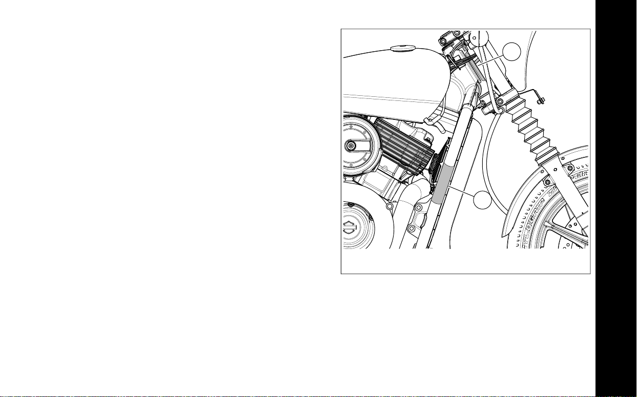
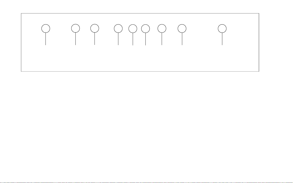
PRIMARY CONTROLS AND SERVICE COMPONENTS
Familiarize yourself with the location of all the controls and
service components on your motorcycle.
NOTES
Harley-Davidson reserves the right to change specifications,
equipment or designs at any time without notice and without
incurring obligation.
See Figure 4 for rider controls and service components
accessible when seated.
See Figure 5 for rider controls and service components
accessible from the right.
See Figure 6 for rider controls and service components
accessible from the left.
Your Motorcycle 21

2
1
7
5
4
6
3
8
om01853g
5.1. Front brake leverClutch hand lever
2. 6.Left hand control module Throttle twist grip
7.3. Ignition switchSpeedometer/odometer
4. 8.Right hand control module Front brake fluid reservoir
Figure 4. Controls and Service Components
22 Your Motorcycle

3
4
2
1
7
6
8
5
om02143Rc
2. 6.Fuse block/main fuse (under side cover) Rear brake pedal
4. 8.Air cleaner Rear brake caliper
5.1. Gas capShock absorber preload collar
7.3. Oil filler dipstickRear brake fluid reservoir
Figure 5. Controls and Service Components
Your Motorcycle 23

2
1
8
3
45
7
6
om02146LB
5.1. Jiffy standCoolant overflow bottle (under side cover)
2. 6.Seat retention screw Gear shift lever
7.3. Front brake caliperShock absorber preload collar
4. 8.Belt tension window Air pressure valve
24 Your Motorcycle
Figure 6. Controls and Service Components

SECURITY SYSTEM
om02290
Components
The security system consists of a control module, a hands-free
antenna mounted on the motorcycle and a hands-free fob
carried by the rider.The security system lamp in the speedometer face indicates when security is armed or disarmed.
See SECURITY SYSTEM, Arming and Disarming.
Options
See a Harley-Davidson dealer or www.harley-davidson.com
for security system options.
SECURITY STATUS INDICATOR
See Figure 7. The security lamp in the speedometer face
indicates the status of the security system.
• Armed: The lamp blinks every few seconds when the
system is armed.
• Disarmed:The lamp will turn off when the system disarms.
• Warning/Alarm:The lamp with stay lit when in a warning
or alarm state.The system is still armed.
• Fob Locator: The lamp will flash quickly when attempting
to locate and connect with the fob.
• Service: See a Harley-Davidson dealer if the lamp remains
lit continuously.
Figure 7. Security Indicator Lamp
ARMING AND DISARMING
Armed
When the motorcycle is parked, motionless and the ignition
switch set to OFF, the security system arms automatically
within 5 seconds.Whether the fob is present or not, the system
will arm.
On arming, the turn signals flash twice and the siren (if
equipped and in chirp mode) chirps twice. While ar med, the
indicator in the speedometer face flashes every few seconds.
25
SECURITY SYSTEM

Disarmed
Fob: An armed security system is automatically disarmed when
the fob is present and the ignition switch is set to IGNITION.
NOTE
Movement like lifting the motorcycle off of its jiffy stand or a
NO FOB condition, will cause the system to electronically seek
the presence of the fob. If the fob is present, the system disarms. See OPERATION, Instruments.
When the system disarms, the siren (if equipped and in chirp
mode) chirps once and the security indicator lamp flashes fast
for several seconds then turns off.
Once disarmed, the rider can ride or move the motorcycle for
parking, storage or service without setting off the alarm.
Personal Identification Number (PIN):If the f ob is misplaced
or if the fob fails to communicate , the system can be disarmed
with the Personal Identification Number (PIN). Refer to
SECURITY SYSTEM, Personal Identification Number (PIN).
ALARM
Warnings
Once armed, if the motorcycle is moved or lifted up off of its
jiffy stand and the fob is not present, the alarm will warn the
operator with three alternate flashes of the turn signals and a
chirp of the siren (if equipped).
Within four seconds, if the motorcycle is back on its jiffy stand
and no further motion is detected, the system will remain armed
without activating the alarm.
If the motorcycle motion continues, the system will issue a
second warning a few seconds after the first.
NOTE
During warnings and alarms, the starter motor and the ignition
circuits remain disabled.
Alarm Activation
If the security system is still detecting motion after a second
warning, the system will activate the alarm.
When activated, the security system will:
• Alternately flash the four turn signals.
• Sound the siren (if equipped).
Duration: If motorcycle motion is detected the system will
repeat the 30 second alarm and will continue to check for
motion.The alarm will repeat this 30 second alarm cycle for 5
minutes (10 cycles) or until no more motion is detected. The
alarm will then deactivate.
26 Security System

NOTE
The alarm will also activate the LED, vibr ation or audible modes
of an optionally purchased Harley-Davidson Security Pager.
See a Harley-Davidson dealer for details.
Alarm Deactivation
Key fob: Bring the fob to the motorcycle. After the module
identifies that the fob is present, the system will terminate the
alarm.
3. Input five digits of the PIN.
a. Press and release the odometer toggle button to cycle
the digit in the PIN.
b. Press and hold the odometer toggle button for 1.5
seconds to enter the number.The display cycles to
the next digit in the PIN.
c. Repeat until all five digits of the PIN have been
entered.
PERSONAL IDENTIFICA TION NUMBER (PIN)
If the fob is misplaced or fails , a personal identification number
(PIN) can disarm the security system.The dealership assigns
the initial PIN.
Disarming with a PIN
NOTE
If a mistake is made while entering the PIN, turn ignition OFF
then back to IGNITION before another attempt.
1. See Figure 8.While the security indicator lamp is flashing,
turn the ignition switch to IGNITION.The odometer window
displays ENTER PIN.
2. Press and release the odometer toggle button. The first
digit space flashes.
NOTES
• If the digit cycles past 9, the digit starts over at 1.
• If any of the digits do not match assigned PIN, the security
system is activated.
4. The vehicle is disarmed and ready to start.
Security System 27

2
1
om02294
1. Odometer window
2. Toggle switch button
Figure 8. Inputting the PIN (Sample PIN Shown)
Changing the PIN
The dealership sets a temporary PIN when they are setting up
the motorcycle for delivery.The owner can change the PIN at
any time.
1. Select a five-digit number (1-9, no zeros).
2. With an assigned fob present, cycle to the ENTER PIN
prompt in the odometer window.
a. See Figure 8. Cycle the ignition switch twice: IGNI-
TION-OFF-IGNITION-OFF-IGNITION.
b. Press and release the odometer toggle button twice
to display the ENTER PIN prompt.
c. On the ENTER PIN prompt, press and hold the odo-
meter toggle button for 1.5 seconds.
d. Ver ify that the current PIN is displayed and the first
digit flashes.
3. The turn signals flash three times.
28 Security System

om00892
4. Repeat until all five digits have been entered.
a. Press and release the odometer toggle button to cycle
the flashing digit to the digit (1-9) that matches your
selected number.
b. To enter the flashing number, press and hold the
odometer toggle button for 1.5 seconds.The display
cycles to the next digit.
5. To store the new PIN, turn the ignition switch to OFF .
6. Record the PIN on the Personal Infor mation page in the
front of this Owner's Manual and on the removable w allet
card.
SECURITY SYSTEM FOB
Assigning Fob
See Figure 9. Key fobs are electronically assigned to the
security system by a Harley-Davidson dealer. Only two fobs
can be assigned at any one time.
Purchase replacement fobs from a Harley-Davidson dealer.
The fobs can only be assigned to an individual motorcycle by
a trained Harley-Davidson technician.
Figure 9. Fob: Security System
Security System 29

NOTES
• The module will arm only if the fob has been assigned by
a Harley-Davidson dealer and a Personal Identification
Number (PIN) has been entered in the system. Record
the PIN on the Personal Infor mation page in the front of
this Owner's Manual and on the removable wallet card.
• If the fob is misplaced or fails, the r ider can refer to the
wallet card and use the PIN to manually disarm the
system. See SECURITY SYSTEM, Arming and Disarming
and SECURITY SYSTEM, Troubleshooting.
• The rider can change the PIN at any time. See SECURITY
SYSTEM, Personal Identification Number (PIN).
Fob Battery
Replace the fob battery every year.
NOTES
• The reusable label found on the fob packaging lists the
serial number of the fob. For reference, affix the label to
a blank "NOTES" page in this Owner's Manual.
• See Figure 10.The serial number of the fob is also found
on the inside of the fob.
1. See Figure 10. To open the fob, turn a thin blade in the
slot (1).
2. Remove the battery (2) and discard in accordance with
local regulations.
3. Install a new battery (Panasonic CR2032 or equivalent)
with the positive side down.
4. Align the two halves of the fob. Snap the halves together.
30 Security System

1
4
2
1
3
om00958a
Riding with a Fob
• Always carry the fob when riding, loading, fueling, moving,
parking or servicing the motorcycle.
• Do not leave the fob attached to the handlebars or store
the fob in a luggage compartment. Unintentionally leaving
the fob with the motorcycle when it is parked prev ents the
system from activating the alarm.
• Do not ride with the fob stored in a metal case or with the
fob closer than 76 mm (3.0 in) to a mobile phone, PDA,
display or other electronic device. Any electromagnetic
interference may prevent the fob from disarming the
system.
1. Thumbnail slot
2. Battery
3. Fob serial number
4. Certification label
Figure 10. Fob Battery
• For added security, always lock the fork and remove the
key when parked. If the fob is within range and the
motorcycle is unlocked, tampering with the motorcycle will
not activate the alarm.
Riding without a Fob
If the motorcycle is ridden without the fob in acceptable proximity, the odometer window temporarily displays "NO FOB."
To restart a motorcycle without a fob, disarm the security
system with the PIN.
Security System 31

TRANSPORT MODE
It is possible to arm the security system without enabling the
motion detector for one ignition cycle.The motorcycle can be
moved in an armed state.The motorcycle cannot be turned on
or started while in transport mode until the fob is present.
To Enter Transport Mode
1. With security fob present, set the ignition switch to IGNITION.
2. Set the ignition switch to OFF.
3. Press the odometer toggle button within 3 seconds.
4. Following a single flash, the turn signals flash three times
to indicate that the system is armed in transport mode.
If the motorcycle will not be operated for sev eral months , such
as during the winter season, see AFTER RIDING, Storing
Motorcycle.
Service Departments
When the motorcycle is left at a Harley-Davidson dealer , there
are two options:
1. Leave an assigned fob with the dealer.
2. To maintain possession of the fob, ask the dealer to disable the system for service (service mode) before leaving
the dealership.
SIREN (IF EQUIPPED)
Chirp Mode
To Exit Transport Mode
With the fob present, set the ignition switch to ignition to disarm
the system and exit transport mode.
STORAGE AND SERVICE DEPARTMENTS
Long-Term Parking
To maintain arming, store the fob beyond the range of the
antenna.The antenna range is approximately 1.5 m (5 ft). Have
the fob present before moving parked motorcycle.
32 Security System
V ehicles with a siren can be set to chirp upon arming and disarming. In chirp mode, the siren sounds two chirps when
arming, and a single chirp when disarming.
Chirpless Mode
In chirpless mode, the siren does not chirp on arming or disarming.
The siren still provides warning chirps and sounds the alarm
if the motorcycle is moved without the fob present.

Switching Modes
3. Pull the main fuse from its holder or disconnect the battery.
Perfor m the following to switch between chirp and chir pless
modes.
1. With security fob present, set the ignition switch to IGNITION.
2. When the security lamp turns off, set the ignition switch
to OFF.
3. When the security lamp turns off (but before the turn signals flash twice), immediately set the ignition switch to
IGNITION.
4. When the security lamp turns off, immediately set the
ignition switch to OFF.
5. When the security lamp turns off (but before the turn signals flash twice), immediately set the ignition switch to
IGNITION. The system changes mode. The siren chirps
or remains silent accordingly.
Disconnecting Power
T o disconnect the battery or remove the main fuse and pre vent
the siren from sounding.
1. Verify that the fob is present.
2. Set the ignition switch to IGNITION.
NOTE
Set the ignition switch to OFF before installing main fuse.
TROUBLESHOOTING
Security Lamp
If the security lamp stays illuminated while riding, see a HarleyDavidson dealer.
Fob
If the security system continues to actuate warnings and alarms
with the fob present, check for:
1. Electromagnetic interference: Other electronic devices ,
power lines, or other electromagnetic sources can cause
the security system to operate inconsistently.
a. V erify that the fob is not in a metal enclosure or within
76 mm (3.0 in) of any other electronic devices.
b. Place the fob on the seat and set the ignition switch
to IGNITION. After the system disarms, return the fob
to a convenient location.
c. Move motorcycle at least 5 m (15 ft) from the spot of
interference.
Security System 33

2. Discharged fob battery: Use the PIN to disarm the
system. Replace the battery. See SECURITY SYSTEM,
Security System Fob.
3. Damaged fob: Use the PIN to disarm the motorcycle.
Replacement fobs are available for purchase from a
Harley-Davidson dealer.
Siren (If equipped)
• If the siren does not chirp two or three times on a valid
arming command from the security module, the siren is
either in the Chirpless Mode, not connected, not working,
or the siren wiring was opened or shorted while the siren
was disarmed.
• If the siren is armed and the internal siren battery is dead,
shorted, disconnected, or has been charging for a period
longer than 24 hours, the siren will respond with three
chirps on arming instead of two.
• The internal siren battery may not charge if the vehicle's
battery is less than 12.5 volts.
• If the siren enters the self-driven mode where it is powered
from the siren's internal 9 volt battery, the turn signal lamps
may or may not alternately flash. If the security module
activates the siren, the turn signal lamps will alternately
flash. If the siren has been armed and a security event
occurs, and the siren is in self-driven mode, the siren will
alarm 20-30 seconds and then turn off for 5-10 seconds.
This alarm cycle will be repeated ten times if the siren is
in the self-driven mode.
34 Security System

REMOVING MOTORCYCLE FROM STORAGE
1. Charge and install the battery. See SERVICE PROCEDURES, Battery Maintenance.
2. Inspect spark plugs. See SCHEDULED MAINTENANCE,
Replacing Spark Plugs.
3. Inspect air filter and replace if necessary. See SCHEDULED MAINTENANCE, Inspecting Air Filter.
4. Inspect drive belt and sprocket. See SCHEDULED
MAINTENANCE, Checking Drive Belt and Sprockets.
5. Perform the items in the BEFORE RIDING, Pre-Ride
Checklist.
5. Check brake fluid level. See SCHEDULED MAINTENANCE, Checking Brake Fluid Level and Changing Brake
Fluid.
6. Inspect brake pads and discs for wear . See SCHEDULED
MAINTENANCE, Inspecting Brake Pads and Discs.
7. Check the hand and foot controls to be sure they are
operating properly. Operate the front and rear brakes,
throttle, clutch and shifter. See OPERATION.
8. Check throttle and brake cables for wear or damage.
9. Check steering for smoothness by turning the handlebar
through the full operating range.
PRE-RIDE CHECKLIST
1. Check the amount of fuel in the tank. Add fuel if required.
See BEFORE RIDING, Filling the Fuel Tank.
2. Adjust mirrors to proper riding positions. See BEFORE
RIDING, Adjusting Mirrors.
3. Check the engine oil lev el. See SCHEDULED MAINTENANCE, Checking Engine Oil Level.
4. Check the coolant level. See SCHEDULED MAINTENANCE, Coolant.
Be sure tires are properly inflated, balanced, undama ged,
and have adequate tread. Inspect y our tires regularly and
see a Harley-Davidson dealer for replacements. Riding
with excessively worn, unbalanced, improperly inflated,
overloaded or damaged tires can lead to tire failure and
adversely affect stability and handling, which could result
in death or serious injury. (00014b)
10. Check tire condition, pressure and motorcycle loading.
Refer to tire specifications on Table 21 for correct inflation
pressure. Refer to Table 22 for weight allowances.
35
BEFORE RIDING

11. Check rear shock settings. Adjust if necessary. See
BEFORE RIDING, Adjusting Shock Absorbers.
12. Check for any fuel, oil, coolant or hydraulic fluid leaks.
13. Check drive belt tension. See SCHEDULED MAINTENANCE, Checking Drive Belt and Sprockets.
Be sure headlamp, tail and stop lamp and turn signals are
operating properly before riding. Poor visibility of rider to
other motorists can result in death or serious injury.
(00478b)
14. Chec k all electrical equipment and s witches including the
stop lamp, turn signals and horn, for proper operation.
15. Service your motorcycle as necessary.
BREAK-IN RIDING RULES
The First 800 Kilometers (500 Miles)
The sound design, quality materials, and workmanship that
are built into your new Harley-Davidson will give you optimum
performance.
To allow your engine to break-in in its critical parts, we
recommend that you observe the riding rules provided below
for the first 800 km (500 mi). Adhering to these r ules will promote future durability and performance of the motorcycle.
1. During the first 80 km (50 mi) of riding, keep the engine
speed below 5000 rpm in any gear. Do not labor the
engine by running or accelerating at very low RPM, or by
running at high rpm longer than needed for shifting or
passing.
2. Up to 800 km (500 mi), vary the engine speed and avoid
operating at any steady engine speed for long periods.
Engine speed up to 7000 rpm in any gear is permissible.
3. Drive slowly and avoid fast star ts at wide open throttle
until the engine has warmed up.
4. Avoid hard braking. New brakes need to be worn in by
moderate use for the first 160 km (100 mi).
FILLING THE FUEL TANK
Avoid spills. Slowly remove filler cap. Do not fill above
bottom of filler neck insert, leaving air space for fuel
expansion. Secure filler cap after refueling. Gasoline is
extremely flammable and highly explosive, which could
result in death or serious injury. (00028a)
36 Before Riding

Use care when refueling. Pressurized air in fuel tank can
force gasoline to escape through filler tube. Gasoline is
extremely flammable and highly explosive, which could
result in death or serious injury. (00029a)
Removing Fuel Filler Cap
1. See Figure 11. Insert the ignition key into the k e y slot (2).
NOTE
The cap pops up as the key is turned.
2. Turn the key clockwise.
3. Remove the filler cap.
Do not spill fuel onto the motorcycle while refueling.
Immediately wipe up fuel spills on your motorcycle. Fuel
can cause damage to cosmetic surfaces. (00147b)
4. Fill the tank. Use only recommended fuel. See BEFORE
RIDING, Fuel System Information.
Installing Fuel Filler Cap
Do not use aftermarket fuel caps. Aftermarket fuel caps
may fit improperly and leak, which could lead to death or
serious injury. See a Harle y-Davidson dealer f or approved
fuel caps. (00034a)
NOTE
The arrow on the cap points to an index tab on the cap. The
index tab aligns with a slot in the fuel opening in the tank.
1. Install the fuel filler cap with alignment arrow (1) pointing
toward the front.
2. Press down around the cap to compress the cap spring.
3. Turn the ignition key counterclockwise to lock the cap.
Before Riding 37

1
2
om01895
1. Alignment arrow
2. Key slot
Figure 11. Fuel Filler Cap
FUEL SYSTEM INFORMATION
Gasoline
Your motorcycle was designed to get the best performance
and efficiency using unleaded gasoline. Most gasoline is
blended with alcohol and/or ether to create oxygenated blends .
The type and amount of alcohol or ether added to the fuel is
important.
Do not use gasoline that contains methanol. Doing so can
result in fuel system component failure, engine damage
and/or equipment malfunction. (00148a)
Use only unleaded fuel in catalytic converter-equipped
motorcycles. Using leaded fuel will damage the emission
control system. (00150b)
• Gasoline/METHYL TERTIARY BUTYL ETHER (MTBE)
blends are a mixture of gasoline and as much as 15%
38 Before Riding

MTBE. Gasoline/MTBE blends use in your motorcycle is
approved.
• ETHANOL fuel is a mixture of ethanol (grain alcohol) and
unleaded gasoline and can have an impact on fuel
mileage. Fuels with an ethanol content of up to 10% may
be used in your motorcycle without affecting vehicle performance. U.S. EPA regulations currently indicate that
fuels with 15% ethanol (E15) are restricted from use in
motorcycles at the time of this publication. Some motorcycles are calibrated to operate with higher ethanol concentrations to meet the fuel standards in certain countries.
• REFORMULATED OR OXYGENATED GASOLINES
(RFG) describes gasoline blends that are specifically
designed to burn cleaner than other types of gasoline.
This results in fewer tailpipe emissions. They are also
formulated to evaporate less when filling the tank. Reformulated gasolines use additives to oxygenate the gas.
Your motorcycle will run normally using this type of fuel.
Harley-Davidson recommends using it whenev er possible
as an aid to cleaner air in our environment.
• Do not use racing fuel or fuel containing methanol. Use
of these fuels will damage the fuel system.
• The only octane booster Harley-Davidson recommends
is SCREAMIN' EAGLE SUPER OCTANE BOOST (avail-
able only in the U.S .).This is the only octane booster that
has been extensively tested and approved for use with
Harley-Davidson engines and components.
• Some gasoline blends might adversely affect starting,
driveability or fuel efficiency. If any of these problems are
experienced, try a different brand of gasoline or gasoline
with a higher octane blend.
Air entrapment and pressurization is a possibility.
Table 4. Minimum Octane Ratings
RATINGSPECIFICATION
87 (91 RON)Pump Octane (R+M)/2
Catalytic Converter
Vehicles in some markets are equipped with catalytic converters.
Do not operate catalytic converter-equipped vehicle with
engine misfire. If you operate the vehicle under this condition, the exhaust will become abnormally hot, which can
cause vehicle damage, including emission control loss.
(00149c)
Before Riding 39

ADJUSTING MIRRORS
Objects in mirrors are closer than they appear . Use caution
when judging distance of objects in mirrors. Failure to
judge correct distances could result in death or serious
injury. (00033a)
Adjust mirrors so you can see a small portion of your shoulders
in each mirror.This will help you establish the relative distance
of vehicles to the rear of your motorcycle.
OPERATING JIFFY STAND
Jiffy Stand Switch: International Models
Some international models have a jiffy stand interlock switch.
The motorcycle will start and run with the jiffy stand down while
the transmission is in neutral. If the jiffy stand is down and the
transmission in gear, engaging the clutch stalls the motorcycle .
Raising the jiffy stand or putting the transmission in neutral will
permit the engine to run.
If the jiffy stand lowers at a speed greater than 15 km/h (10
mph), the engine will continue to run and the rider may continue
to ride while in this mode.
Location
Be sure jiffy stand is fully retracted before riding. If jiffy
stand is not fully retracted, it can contact the r oad surface
causing a loss of vehicle control, which could result in
death or serious injury. (00007a)
See Figure 6. The jiffy stand (5) is located on the left side of
the motorcycle.
40 Before Riding
Always park motorcycle on a level, firm surface. An
unbalanced motorcycle can fall over, which could result
in death or serious injury. (00039a)
ADJUSTING SHOCK ABSORBERS
General
Adjust the rear shock absorber spring preload for the weight
the motorcycle is to carry. Notice the adjustment settings as
you turn the collar.
Adjust both shocks the same number of turns.

Adjustment
Adjust both shock absorbers equally . Improper adjustment
can adversely affect stability and handling, which could
result in death or serious injury. (00036b)
Do not turn the shock absorber adjustment collar clockwise beyond adjustment setting 5. Doing so ma y result in
equipment damage. (00166b)
NOTE
See Figure 12. Do not turn the preload cam from position five
(5) to position one (1) or from position one (1) to position five
(5).
1. Put the SP ANNER WRENCH (Part No. HD-51439) around
the lower collar of the shock absorber.
2. Turn the spring adjusting cam to the desired position.
When returning to off-cam position, back the cams off in
the opposite direction.
a. Turn the collar toward higher numbers to increase
the preload. Refer to Table 5.
b. T urn the collar toward the lo wer numbers to decrease
the preload.
Before Riding 41

1
2
3
4
5
om02125
Figure 12. Shock Absorber Preload Adjustment
Table 5. Recommended Shock Preload: Five Position
POSITIONLOAD*
1Less than
75 kg (165 lb)
275-89 kg (165-195 lb)
389-102 kg (195-225 lb)
4102-116 kg (225-255 lb)
5116 kg (255 lb)
to maximum added weight allowed.
* Add the weight of the rider, passenger, riding gear,
accessories, and cargo.
Table 6. Maximum Added Weight Allowed
MAX LOADMODEL
lbkg
461209XG500
461209XG750
42 Before Riding

N
2
3
4
5
1
6
om02128
CONTROLS, INSTRUMENTS AND SWITCHES
Clutch Hand Lever
Do not position fingers between hand control lever and
handlebar grip. Improper hand positioning can impair
control lever operation and cause loss of vehicle contr ol,
which could result in death or serious injury. (00032a)
See Figure 4. The clutch hand lever (1) is operated with the
fingers of the left hand. See OPERATION, Shifting Gears.
Gear Shift Lever
See Figure 13. The gear shift lever is operated with the left
foot. Neutral is found between first and second gear in the six
speed shift pattern. See OPERATION, Shifting Gears.
OPERATION
Figure 13. Shift Pattern and Shift Lever
Left-Hand Control Module
See Figure 4. Operate the switches on the left hand control
module (2) with the thumb of the left hand. See OPERATION,
Left Hand Control Switches.
43

Speedometer/Odometer
See Figure 4. The current road speed is displayed in the
speedometer (3).The accumulated mileage and individual trip
mileage is displayed in the odometer window in the f ace of the
speedometer. See OPERATION, Instruments.
Right-Hand Control Module
See Figure 4. Operate the switches on the right hand control
module (4) with the thumb of the right hand. See OPERATION,
Right Hand Control Switches.
Brakes
Do not position fingers between hand control lever and
handlebar grip. Improper hand positioning can impair
control lever operation and cause loss of vehicle contr ol,
which could result in death or serious injury. (00032a)
Front brake lever: See Figure 4. The front brake lever (5)
controls the front brake. Operate the hand le ver with the fingers
of the right hand.
Rear brake pedal: See Figure 5. The rear brake pedal (6)
activates the rear wheel brake.
Do not apply brake strongly enough to lock the wheel. A
locked wheel will skid and can cause loss of vehicle control, which could result in death or serious injury. (00053a)
Apply brakes evenly to prevent wheels from locking up. A balance between rear and front brake is best.
Throttle Twist Grip
Accelerate: See Figure 4. Slowly twist throttle twist grip (6)
backward (toward rear of motorcycle) to open the throttle.
Decelerate: Slowly twist throttle control grip forward (toward
the front) to close the throttle.
Ignition Switch
NOTE
Required by law, the headlamp and tail lamps operate when
the switch is in the IGNITION position.
See Figure 4. Unlock the ignition switch (7) with the ignition
key. Rotate the s witch to the desired position. Refer to Table 7.
To start the engine, see OPERATION, Starting the Engine.
44 Operation

1
2
3
4
om02127
Fork Lock
T urn the ignition switch to the OFF position before loc king
the motorcycle. Leaving the switch in the ACC position
will keep the instrument lights on and result in a discharged battery. (00492b)
Protect your vehicle against theft. After parking your
motorcycle, lock the steering head and ignition switch.
Failure to lock your motorcycle can result in theft and/or
equipment damage. (00491c)
See Figure 14. Park your motorcycle. Use the fork lock to discourage theft or unauthorized use. Refer to Table 7.
1. Turn the fork full left.
2. Insert the key into the switch.
3. Push the key in and turn to LOCK.
4. Remove the key.
1. IGNITION
2. ACC
3. OFF
4. LOCK
Figure 14. Ignition and Fork Lock Switch
Operation 45

Table 7. Ignition Switch and Fork Lock
1
5
4
2
3
om02259a
FUNCTIONNAMESWITCH
ACC
IGNITION
Turns on accessories. Instrument
lamps are on. Brake lamp and
horn can be activated.
Turns on ignition, lamps and
accessories.The engine will start
and run.
Front fork locked.LOCK
OFF
Turns off ignition, lamps and
accessories. Motorcycle is turned
off and cannot be started.
Push to lock the front fork.PUSH
INSTRUMENTS
Speedometer
See Figure 15. The speedometer is calibrated in miles per
hour, (mph) (1), kilometer per hour (km/h) (3) or in dual miles
per hour (mph) and kilometers per hour (km/h) (2).
46 Operation
1. mph
2. mph/km/h
3. km/h
4. Odometer toggle button
5. Odometer/tachometer display
Figure 15. Speedometer/Tachometer

2
1
3
4
5
om02123c
Gear/Tachometer
See Figure 16. With the ignition on, press and release the
toggle switch button to toggle through the odometer displays
to the gear/tachometer display (5). The display shows the
current gear selection and the engine speed in revolutions per
minute (rpm).
NOTE
The gear selection number only changes to match the current
gear when the motorcycle is moving.
Odometer: Mileage,Trip A,Trip B
See Figure 16. With the ignition on, press and release the
toggle switch button (2) to toggle between the odometer (1),
trip odometer A (3) and trip odometer B (4).
To reset a trip odometer to zero, press and hold the toggle
switch button.
1. Odometer
2. Toggle switch button
3. Trip A
4. Trip B
5. Gear/tachometer
Figure 16. Gear/Tachometer/Odometer
Operation 47

Odometer Messages
Low Fuel Trip Meter (LF): See Figure 17.When the low fuel
indicator illuminates in the speedometer face, a low fuel message (LF) (1) appears in the odometer window with a mileage
number. See OPERATION, Indicators.
The displayed mileage is not the remaining fuel mileage, it is
a count up display. The displayed LF mileage indicates the
point the low fuel indicator activated.
Tip (tiP): See Figure 17.When the motorcycle is tipped over,
the work "tiP" (2) appears in the odometer window.The engine
does not restart until the ignition is reset.
To reset, pick up the motorcycle and cycle the ignition switch
OFF-IGNITION.
Fob Low Battery (FOB LOW BATT): See Figure 17. If the
battery in the security fob is low, the message "FOB LOW
BATT" (3) will scroll in the odometer widow. Change the fob
battery. See SECURITY SYSTEM, Security System Fob
Transport Mode Active (tSPORT MODE ACTIVE): See
Figure 17.The security system is in the transport mode when
the "tSPORT MODE ACTIVE" message (4) will scroll in the
odometer window . See SECURITY SYSTEM, T ransport Mode.
No Fob (NO FOB): See Figure 17. When the system cannot
communicate with the fob, this message (5) is displayed. See
SECURITY SYSTEM, Troubleshooting.
48 Operation

2
3
1
4
5
om02278c
1. Low fuel trip meter
2. Tip
3. Low fob battery (scroll)
4. Transport mode (scroll)
5. No fob
Figure 17. Odometer Window Messages
Clock
See Figure 18. With the ignition on, press and release the
toggle switch button to toggle through the odometer displays
to the time display.
To set the time:
1. Press and hold the toggle switch button until 12h (2) begins
blinking in the odometer display. Release the toggle.
2. Press and release the toggle once (3) to advance to a
blinking 24h or military style display. Each press and
release of the toggle, switches the display between 12h
and 24h.
3. When the desired time style is displayed, press and hold
the toggle (4) until the hours are blinking.
4. Press and release the toggle repeatedly (5) to advance
the hours.
5. When the correct hour is displayed, press and hold the
toggle until the minutes (6) start blinking.
6. Press and release the toggle switch button repeatedly to
advance the minutes display (7).
7. When the correct minute is displayed, press and hold the
toggle until the minutes stop blinking.
Operation 49

1
2
3
6
4
5
7
om02277c
Figure 18. Setting the Clock
LEFT HAND CONTROL SWITCHES
High Beam
The automatic-on headlamp feature provides increased
visibility of the rider to other motorists. Be sure headlamp
is on at all times. P oor visibility of rider to other motorists
can result in death or serious injury. (00030b)
See Figure 19. Press the high beam switch (1) to select the
headlamp high beam.The high beam indicator illuminates when
the high beam is on. Refer to Table 8.
Low Beam
See Figure 19. Press the low beam switch (2) to select the
headlamp high beam. Refer to Table 8.
Left Turn
See Figure 19. Press the turn signal switch left to activate the
left turn signal.The signal flashes until it is manually canceled.
To cancel, push the center button to center detent. Refer to
Table 8.
50 Operation

3
1
4
5
2
om02121
Right Turn
See Figure 19. Press the turn signal switch right to activate
the right turn signal. The signal flashes until it is manually
canceled.To cancel, push the center button to center detent.
Refer to Table 8.
Horn
See Figure 19. Press the horn switch to sound the horn. Ref er
to Table 8.
1. High beam
2. Low beam
3. Left turn
4. Right turn
5. Horn
Figure 19. Left Hand Control Switches
Operation 51

Table 8. Left Hand Control Switches
FUNCTIONNAMESWITCH
High
beam
Low beam
Left turn
Press the switch to switch the headlamp to high beam.
Press the switch to switch the headlamp to low beam.
Press the switch to the left to activate
the left turn signal.
Run
See Figure 20. Press the off/run switch to r un (2) to turn on
the electrical circuits to the engine. With the off/run switch in
the run (2) position, the engine starts and runs. Refer to
Table 9.
Start
See Figure 20. With the off/run switch in run, press the start
switch (3) to start the engine. Refer to Table 9.
Right turn
Press the switch to the right to activate
the right turn signal.
Press the switch to sound the horn.Horn
RIGHT HAND CONTROL SWITCHES
Off
See Figure 20. Press the off/run s witch to off (1) to turn off the
engine. With the off/r un switch in the off position, the engine
cannot start or run. With the off/run switch in the run position,
the engine starts and runs. Refer to Table 9.
52 Operation

1
2
3
om02120
Table 9. Right Hand Control Switches
FUNCTIONNAMESWITCH
Run
Press the switch to the run position to
allow the engine to run.
1. Off
2. Run
3. Start
Figure 20. Right Hand Control Switches
Off
Press the switch to the off position to
stop the engine or to prevent the
engine from starting.
Press the switch to start the engine.Start
ANTI-LOCK BRAKE SYSTEM (ABS)
Identification
See Figure 21. Street models with the ABS option can be
identified by the ABS module (EHCU) mounted at the lower
left front corner in front of the radiator.
Operation 53

om02258
BRAKE SYSTEM
Front Brake Lever
Do not position fingers between hand control lever and
handlebar grip. Improper hand positioning can impair
control lever operation and cause loss of vehicle contr ol,
which could result in death or serious injury. (00032a)
The front brake hand lever controls the front wheel brake and
is located on the right handlebar. Operate the hand lever with
the fingers of the right hand.
Rear Brake Pedal
The rear brake pedal controls the rear wheel brake and is located on the right side. Operate the rear brake pedal with the
right foot.
Figure 21. ABS Module (EHCU)
Non-ABS Brake System
Apply brakes uniformly and evenly to prevent wheels from
locking. Use front and rear brakes equally for best results.
54 Operation

Do not apply brake strongly enough to lock the wheel. A
locked wheel will skid and can cause loss of vehicle control, which could result in death or serious injury. (00053a)
Anti-lock Brake System (ABS)
The optional Harley-Davidson anti-lock brake system assists
the rider in maintaining control when braking in a straight-line
emergency situation. ABS operates independently on front and
rear brakes to keep the wheels rolling and pre vent uncontrolled
wheel lock-ups either on dry pavement or on slick surfaces
such as gravel, leaves or when riding in wet conditions.
How ABS Works
The ABS monitors sensors at the front and rear wheels to
determine wheel speed. If the system detects one or both
wheels are slowing down too quickly, which indicates they are
close to locking, the ABS reacts. If the deceleration rate does
not match a criteria stored in memory, the ABS also reacts.
The system rapidly opens and closes valves to modulate the
brake caliper pressure utilizing only the brake lever/pedal
pressure being applied by the rider. During ABS activation, the
system provides the electronic equivalent of manually pumping
the brakes. ABS is capable of cycling up to seven times per
second.
The rider will recognize ABS activation by the slight pulsing
sensation in the hand lever or the rear brak e pedal.The pulsing
sensation may also be accompanied by a clicking sound from
the ABS module. Both are the result of normal operation. Ref er
to Table 10.
How To Use ABS
While an advantage in emergency braking, ABS is not a substitute for safe riding.The safest way to stop a motorcycle is
upright with both wheels straight.
Harley-Davidson ABS is a manual assist system.When stopping in an emergency stopping situation, maintain pressure on
the brakes through all ABS ev ents. Do not modulate or "pump"
the brake controls.The wheels will not lock until the end of the
stop when motorcycle speed reaches approximately 6 km/h (4
mph) and ABS is no longer needed.
Operation 55

ABS:Tires and Wheels
ABS cannot prevent lockup of rear wheel due to engine
braking. ABS will not aid in cornering or on loose/uneven
surfaces. A locked wheel will skid and can cause loss of
vehicle control, which could result in death or serious
injury. (00362a)
Table 10. ABS Symptoms and Conditions
ABS malfunction detected. See a Harley-Davidson dealer for service.ABS lamp continuously lit
ABS lamp flashing
ABS event
This indicates a normal self-diagnostics process when the motorcycle is first turned
on and the speed is under 5 km/h (3 mph). ABS is not operational until the lamp turns
off. If the lamp continues flashing at speeds greater than 5 km/h (3 mph), see a HarleyDavidson dealer for service.
Normal condition.Pulsing brake lever or pedal during an
Normal condition.Clicking sound during an ABS event
Motorcycles equipped with ABS must always use Harley-Da vidson tires and wheels.The ABS monitors the rotational speed
of the wheels through individual wheel speed sensors. Changing to different diameter wheels or different-sized tires can
alter the rotational speed.This can upset the calibration of the
ABS and have an adverse effect on its ability to detect and
prevent uncontrolled wheel loc kups. Operating at tire pressures
other than those specified in T ab le 21 can reduce ABS braking
performance.
CONDITIONSYMPTOM
56 Operation

"Surge" sensation while braking
Temporarily stiff rear brake pedal
Black mark on pavement
Wheel lock at low speed
Table 10. ABS Symptoms and Conditions
CONDITIONSYMPTOM
Normal condition.This is most noticeable when braking with one brake (front only or
rear only). Result of a reduction in deceleration which can be caused by cracks or
bumps in road, engine braking (high engine RPMs causing the rear wheel to slow
down), hard braking at slow speeds, and other conditions.This is due to ABS modulating caliper brake pressure to prevent uncontrolled wheel lock.
Normal condition. Engine braking (high engine RPMs causing the rear wheel to slow
down) or down shifting can activate ABS . If applying the rear brake at the same time
or immediately after, the ABS may be closing a valve to prevent pressure to the rear
brake.This is due to ABS modulating caliper brake pressure to prevent uncontrolled
wheel lock.
Normal condition. Depending on surface, tire can chirp without locking the wheel.Tire chirp
Normal condition. Depending on surface , tire can leave a black mark without locking
the wheel.
Normal condition. ABS does not activate on front wheel below 5 km/h (3 mph) or on
rear wheel below 8 km/h (5 mph).
Operation 57

om02262a
INDICATORS
See Figure 22. Indicator lights in the speedometer face illuminate to indicate the status of the associated motorcycle
function. Refer to Table 11.
Figure 22. Indicator Lights
58 Operation

Table 11. Indicator Lights
Table 11. Indicator Lights
Security
system
Neutral
Left turn
Oil
pressure
ABS
FUNCTIONNAMEICON
• A flash every three seconds
indicates that the security
system is armed.
• Disarmed, the lamp remains
illuminated for four seconds
before turning off.
• If continuously illuminated, see
a Harley-Davidson dealer.
Illuminates when transmission is in
neutral.
Flashes when turn signal switch is
activated for a left turn. Push center
button on turn signal switch to
cancel.
If indicator remains lit, stop engine
and check oil level.
Flashes until 5 km/h (3 mph) and
ABS becomes operational.
Coolant
temperature
High beam
Right turn
Check
engine
FUNCTIONNAMEICON
Illuminates when temperature
exceeds a safe maximum.
Illuminates when high beams are on.
To switch to low beam, press the low
beam switch.
Flashes when turn signal switch is
activated for a right turn. Push center
button on turn signal switch to
cancel.
• Illuminates briefly when ignition
switch is in IGNITION or ACC
position.
• If indicator illuminates at any
other time, see a Harley-Davidson dealer for diagnostic
assistance.
Operation 59

Table 11. Indicator Lights
Low fuel
• Illuminates when fuel level is at
approximately 3.1 L (0.8 gal) or
less. Fill with recommended fuel
as soon as possible.
• May remain illuminated up to 3
minutes after refueling.
• See a Harley-Davidson dealer if
lamp flashes continuously.
NOTE
The engine lamp will light for approximately 4 seconds and the
FUNCTIONNAMEICON
fuel pump will run for approximately 2 seconds.
4. Squeeze the clutch lever in against the handgrip.
5. Press the start switch.
NOTE
If engine does not start, verify engine off/run switch is in run
position.
STARTING THE ENGINE
Before starting engine, be sure throttle control will snap
back to idle position when released. A thr ottle control that
prevents engine from automatically returning to idle can
lead to loss of control, which could result in death or serious injury. (00390a)
1. Verify that the motorcycle is in neutral.
2. Press the engine off/run switch to the run position.
3. Turn ignition switch to IGNITION. Do not twist the throttle.
60 Operation
The engine should be allowed to run slowly for 30-60
seconds.This will allow the engine to warm up and let oil
reach all surfaces needing lubrication. Failure to comply
can result in engine damage. (00181b)
6. Raise the jiffy stand before beginning forw ard mov ement.

STARTING AFTER TIPOVER
Starting from a Stop
If tip occurs, check all controls for proper operation.
Restricted control movement can adversely affect the
performance of the brakes, c lutch or ability to shift, which
could result in loss of vehicle control and death or serious
injury. (00350a)
After a tipover, reset the ignition before starting the engine.
1. Set the motorcycle upright.
2. Reset the ignition by turning the ignition switch OFFIGNITION.
SHIFTING GEARS
Finding Neutral
NOTE
If the gears do not disengage when the engine is off, with the
clutch engaged rock the motorcycle backward and forward
while pressing or lifting the shift lever.
Neutral is between first and second gear. Select neutral by
either a half lift from first gear or a half press from second gear.
The clutch must be fully disengag ed before attempting a
gear shift. Failure to fully disengage the clutch can result
in equipment damage. (00182a)
NOTE
Partially open the throttle so the engine does not drag when
the clutch lever is released.
1. With the engine running and the jiffy stand retracted,
squeeze the clutch lever in against the handlebar gr ip to
disengage the clutch.
NOTE
Always start forward motion in first gear.
2. Press the gear shift lever down to end of its travel and
release.The transmission is now in first gear.
3. Ease out the clutch lever and at the same time, g radually
open the throttle.
Operation 61

Upshift (Acceleration)
NOTE
Disengage the clutch completely before each gear change.
See Figure 23. Shift to the next higher gear when the motorcycle reaches the shifting speed. Refer to Table 12.
1. Close the throttle.
2. Slowly pull clutch hand lever in against handlebar gr ip to
fully disengage clutch.
3. Lift the gear shift lever up to the end of its travel and
release.
4. Ease out the clutch lever and, at the same time, g radually
open the throttle.
5. Repeat the previous steps to engage remaining gears.
Table 12. Recommended Upshift Speeds
km/hmphGEAR CHANGE
2515First to second
4025Second to third
5535Third to fourth
7045Fourth to fifth
8555Fifth to sixth
62 Operation

6
N
1
2
3
4
5
om02129
Downshift (Deceleration)
Do not downshift at speeds higher than those listed.
Shifting to lower gears when speed is too high can cause
the rear wheel to lose traction and lead to loss of vehicle
control, which could result in death or serious injury.
(00045b)
See Figure 24. When engine speed decreases, as when
climbing a hill or slowing for a turn, shift to the next low er gear .
Refer to Table 13.
1. Close the throttle.
Figure 23. Upshift Pattern
2. Slowly pull clutch hand lever in against handlebar gr ip to
fully disengage clutch.
3. Press the gear shift lever down to the end of its tr av el and
release.
4. Ease out the clutch lever and gradually open the throttle.
5. Repeat the previous steps to engage remaining gears.
Operation 63

6
5
4
3
2
1
om02130
Shift to neutral before stopping engine. Shifting mechanism can be damaged by shifting gears while engine is
stopped. (00183a)
The gear shifter mechanism permits shifting the transmission
to neutral from either first or second gear.
Table 13. Recommended Downshift Speeds
km/hmphGEAR CHANGE
8050Sixth to fifth
6540Fifth to fourth
5030Fourth to third
3020Third to second
1510Second to first
64 Operation
Figure 24. Downshift Pattern
STOPPING THE ENGINE
1. Push the off/run switch to off.
2. Turn ignition switch to off.
NOTE
If the engine stalls or stops for any reason, turn the ignition
switch off to prevent battery discharge.

STORING MOTORCYCLE
If the motorcycle will not be operated for several months, take
steps to protect the motorcycle. Always protect parts against
corrosion, preserve the battery and prevent the build-up of gum
and varnish in the fuel before storage.
Make a list of ever ything you do and fasten it to a handlebar
grip.When you take the motorcycle out of storage, this list is
your reference/checklist to get your motorcycle in operating
condition.
Do not store motorcycle with gasoline in tank within the
home or garage where open flames, pilot lights, sparks or
electric motors are present. Gasoline is extremely flammable and highly explosive, which could result in death
or serious injury. (00003a)
1. Fill fuel tank. Add a gasoline stabilizer. Use one of the
commercially available gasoline stabiliz ers and follow the
manufacturer's instructions.
2. Warm motorcycle to operating temperature. Change oil
and turn engine over to circulate the new oil. See
SCHEDULED MAINTENANCE, Changing Engine Oil and
Filter.
3. Prepare battery for storage. See SERVICE PROCEDURES, Battery Maintenance.
4. Check and fill the cooling system. See SCHEDULED
MAINTENANCE, Coolant.
5. To protect the body panels, engine, chassis and wheels
from corrosion, follow the cosmetic care procedures bef ore
storage. See AFTER RIDING, Cleaning and General Care.
6. Cover the motorcycle with a material such as light canvas
that breathes. Plastic mater ials that do not breathe promote condensation and corrosion.
CLEANING AND GENERAL CARE
• Harley-Davidson cleaning products are tested extensiv ely
for use on motorcycle surfaces .These products are formulated to be compatible with one another. See a HarleyDavidson dealer to purchase recommended cleaning
products. Refer to Table 14 and Table 15.
• Care, cleaning and protection of the vehicle surfaces is
the responsibility of the owner.
• Clean and protect the cosmetic surfaces on your motorcycle as often as possible to inhibit rust and corrosion.
• Some painted finishes and other surfaces may be
scratched if gravel, dir t or grime are rubbed across the
65
AFTER RIDING

surface during washing. Use clean towels and avoid rubbing sediment across gloss finishes.
• Do not use paper towels, cloth diapers or other materials
with nylon fibers which can cause fine scratches to surfaces.
• For repair of scratched surfaces, see a Harley-Davidson
dealer.
Observe warnings on labels of cleaning compounds.
Failure to follow warnings could result in death or serious
injury. (00076a)
Do not wash brake discs with cleaners containing chlorine
or silicone. Cleaners containing chlorine and silicone can
impair brake function, which could result in death or serious injury. (00077a)
Do not use a pressure washer to clean motorcycle. Using
a pressure washer can result in equipment damage.
(00489c)
Use of abrasive products or powered buffing equipment
will cause permanent cosmetic damage to body panels.
Use only recommended products and techniques outlined
in this manual to avoid damaging body panels. (00245b)
66 After Riding

Cleaning Wheels and Tires
NOTE
Corrosion to wheels is not considered to be a defect in materials or workmanship.
• Wheels can corrode or be cosmetically damaged if they
are not properly cleaned, polished and preserved.
• Harley-Davidson recommends that wheels be cared for
weekly.
• Keep wheels clean from harsh chemicals, acid-based
wheel cleaners, salt, and accumulated brake dust.
Table 14. Recommended Cleaning and Care Products
• After washing wheels with WHEEL & TIRE CLEANER,
use the polish and sealing products according to the type
of wheels on your motorcycle. Refer to Table 14.
Radiator
See SCHEDULED MAINTENANCE, Cleaning Radiator for
important information regarding the cleaning of the radiator.
RECOMMENDED CLEANING PRODUCTS
The following products are recommended f or Harley-Davidson
motorcycles, parts and accessories.Your motorcycle may not
have all the components shown in the tables.
PART NO.
BARE ALUMINUM WHEEL
PROTECTANT - INDI-
VIDUAL WIPES
93600063
BARE METAL POLISH
93600028 (U.S.)
93600083 (Non-U.S.)
surfaces.
aluminum or polished stainless steel
surfaces.
FRAMEPURPOSEPRODUCT
PANELS
WHEELSBODY
FINISH
As applicablePolishes non-clear coated polished
OTHERDENIM
"Burst"NoYesNoNoCorrosion control for bare aluminum
collection
After Riding 67

Table 14. Recommended Cleaning and Care Products
PART NO.
BLACK LEATHER
REJUVENATOR
93600033 (U.S.)
93600081 (Non-U.S.)
BOOT MARK REMOVER
93600001 (U.S.)
93600069 (Non-U.S.)
BUG REMOVER
93600022 (U.S.)
93600075 (Non-U.S.)
CHROME CLEAN & SHINE
93600031 (U.S.)
93600082 (Non-U.S.)
93600064 (U.S.)
93600078 (Non-U.S.)
ENGINE BRIGHTENER
93600002 (U.S.)
93600068 (Non-U.S.)
they look brand new.
exhaust components.
painted surfaces. Also available as
individual wipes (93600065).
cleans brushed aluminum or stainless
steel surfaces.
finish.
FRAMEPURPOSEPRODUCT
PANELS
WHEELSBODY
FINISH
NoNoNoNoRejuvenates black leather products so
NoNoNoNoRemoves boot marks from chrome
YesYesYesYesRemoves bugs from metal, plastic or
As applicableShines chrome-plated surfaces and
YesYesYesYesWaterless quick cleaner and detailer.DENIM PAINT CLEANER
NoNoNoNoRejuvenates wrinkle black engine
OTHERDENIM
Black
leather
goods
Exhaust
system
Wrinkle
black
engines
68 After Riding

Table 14. Recommended Cleaning and Care Products
PART NO.
GLAZE POLY SEALANT
93600026 (U.S.)
93600079 (Non-U.S.)
GLOSS DETAILER
93600062 (U.S.)
93600073 (Non-U.S.)
93600007
LEATHER PROTECTANT
93600034 (U.S.)
93600080 (Non-U.S.)
QUICK WASH
93600012 (U.S.)
93600071 (Non-U.S.)
93600025 (U.S.)
93600074 (Non-U.S.)
paint surfaces and chrome.
tion. Allows chrome to breathe, unlike
wax. Good for windshields. Also available as individual wipes (97401-10).
products.
cycle. Cleans all surfaces, sheeting
action prevents spots.
FRAMEPURPOSEPRODUCT
PANELS
YesYesProvides a protective barrier for glossy
WHEELSBODY
FINISH
NoAs applic-
able
NoYesYesYesProduces high gloss with UV protec-
YesYesYesYesT ra vel size cleaning and care products .HARLEY TRA VEL CARE KIT
NoNoNoNoWeatherproofs and preserves leather
YesYesYesYesA quick wash for a lightly soiled motor-
NoNoYesYesRemoves fine scratches and swirls.SCRA TCH & SWIRL REPAIR
OTHERDENIM
Leather
goods
After Riding 69

Table 14. Recommended Cleaning and Care Products
PART NO.
SEAT, SADDLEBAG & TRIM
CLEANER
93600010
SPRAY CLEANER &
POLISH
93600029 (U.S.)
93600084 (Non-U.S.)
SUNWASH BIKE SOAP
93600023 (U.S.)
93600077 (Non-U.S.)
WHEEL & TIRE CLEANER
93600024 (U.S.)
93600076 (Non-U.S.)
and plastic. Use on seats , saddlebags,
inner fairings and any other trim.
Reduces static attraction to dust.Works
great for removing bugs.
a wash mitt. Reduces hard water spots
when washing a motorcycle in the sun.
from wheels, tires and whitewalls. Do
not use on frames or anodized parts.
FRAMEPURPOSEPRODUCT
PANELS
WHEELSBODY
FINISH
NoNoNoNoCleans and conditions vinyl, leather
NoYesYesYesAerosol quick cleaner and detailer.
YesYesYesYesThorough washing of all surfaces with
NoYesNoNoRemoves brake dust and road grime
OTHERDENIM
Seats,
saddle-
bags and
trim
Black-
coated
exhaust
pipes and
mufflers
70 After Riding

Table 14. Recommended Cleaning and Care Products
PART NO.
WINDSHIELD CLEANER
93600067
WINDSHIELD WATER
REPELLENT
93600032 (Global)
PART NO.
BUG EATER SPONGE
93600110
94844-10
93600107
single use wipe.
from the windshield.
Table 15. Recommended Surface Care Products
When paired with water and BUG REMO VER, the BUG EA TER SPONGE breaks
down and dissolves baked on bugs and road grime.
Brush kit for detailing your motorcycle.CLEANING BRUSH KIT
Large cotton swabs for cleaning crevices and detailed surfaces.DETAILING SWABS
FRAMEPURPOSEPRODUCT
PANELS
PURPOSEPRODUCT
WHEELSBODY
FINISH
NoNoYesYesQuick windshield cleaner in convenient
NoNoNoNoAllows water to bead and dissipate
OTHERDENIM
Windshield
Windshield
After Riding 71

Table 15. Recommended Surface Care Products
PART NO.
DISPOSABLE DETAILING SOFT CLOTH
93600114
94811-10
94651-09 (120 V)
94865-09 (220 V)
MICROFIBER DETAILING CLOTH
94663-02
SYNTHETIC DRYING CHAMOIS
94791-01
94760-99
43078-99
PURPOSEPRODUCT
Non-absorbent cloth for applying and buffing SWIRL & SCRATCH REPAIR and
GLAZE POLY SEALANT to painted surfaces or chrome.
Wash bucket with apron to hold your supplies. Includes GRIT GUARD insert.HARLEY WASH BUCKET
Blows a stream of warm dry filtered air. Reduces streaks and water spots.HOG BLASTER MOTORCYCLE DRYER
Highly absorbent detailing cloth for polishing and sealing. Contains no nylon
fibers.
Extra-absorbent, non-streaking synthetic towel for drying. Dampen towel and
wring out before using for greatest absorbency.
Absorbent wool-blended washing mitten.WASH MITT
Cone-shaped scrub brush for wheels.WHEEL & SPOKE BRUSH
72 After Riding

stainless steel
Table 16. Wheel Polish and Sealing Products
GLAZE POLY SEALANTAnodized
GLOSS DETAILER
BARE ALUMINUM WHEEL PROTECTANTBare aluminum
GLOSS DETAILER
BARE METAL POLISHPolished aluminum or
DESCRIPTIONPRODUCTWHEELS
Cleans surface, removes fine scratches. Provides a
breathable sealant against acid, chemicals, salt and brake
dust.
Seals and protects against harsh chemicals, salt and other
sediments to prevent corrosion.
Creates a protective coating for bare aluminum wheels to
prevent oxidation. Individual wipe.
Non-abrasive cleaner to brighten chrome wheels.CHROME CLEAN & SHINEChrome
Seals and protects against harsh chemicals, salt and other
sediments to prevent oxidation.
Microabrasive polish to refurbish polished wheels. Do not
use on chrome.
WASHING THE MOTORCYCLE
Use only recommended cleaning and care products. Refer to
Table 14 and Table 15.
NOTE
During rinsing and washing, avoid direct spray on electrical
components and any luggage or saddlebag sealing areas (if
equipped). Avoid spraying water under leather saddlebag
covers (if equipped).
After Riding 73

Preparation
Washing the Motorcycle
1. Allow motorcycle to cool before rinsing or washing.
Spraying water on hot surf aces can leave w ater spots and
mineral deposits.
2. Rinse the motorcycle from the bottom up.
3. To loosen dried bugs or hardened dirt, allow surfaces to
soak under a damp towel.
Cleaning Wheels and Tires
1. Rinse wheel and tire surfaces. A void splashing br ake dust
on chrome or painted parts.
2. Apply WHEEL & TIRE CLEANER. Allow cleaner to set for
one minute.
3. Clean the wheel with a BUG EATER SPONGE or WHEEL
& SPOKE BRUSH.Thoroughly scrub all brake dust and
other sediments off the wheel. Accumulated brake dust
can trap moisture and dirt, which leads to wheel corrosion.
4. Rinse well.
NOTE
See the appropriate instructions in this section for cleaning
leather, denim (flat) finishes, windshields or other special surfaces.
1. If necessary, use BUG REMOVER to remove bug splatters.
a. Rinse the affected surfaces during preparation.
b. Spray the area with BUG REMOVER.
c. Wait one minute while the BUG REMOVER penet-
rates the bug splatters.
d. Use the BUG EATER SPONGE while washing to
easily remove bugs.
2. Prepare the wash.
a. Fill a HARLEY WASH BUCKET with clean water.
b. Add SUNWASH BIKE SOAP, following the directions
on the package.
c. Soak the WASH MITT and/or a BUG EATER
SPONGE in the SUNWASH solution.
74 After Riding

3. Wash all surfaces starting at the top working down toward
the ground.
4. Rinse the motorcycle twice in both directions:
a. Rinse from the bottom up.
b. Rinse from the top down.
Drying the Motorcycle
1. Dry the surfaces from the top down using a SYNTHETIC
DRYING CHAMOIS or a HOG BLASTER MO TORCYCLE
DRYER. Avoid using any type of forced air on speakers
or other sensitive components.
2. Dampen chamois in clean water and wring out the excess.
The chamois is more absorbent when wet.
3. Wipe across the vehicle surface.
4. Repeat as necessary until surface is dry.
Polishing and Sealing
NOTE
If motorcycle has denim finish, skip the Polishing and Sealing
procedure.
1. Apply GLAZE POLY SEALANT with a DISPOSABLE
DETAILING SOFT CLOTH or MICROFIBER DETAILING
CLOTH, following the instructions on the package.
2. Buff with a DISPOSABLE DETAILING SOFT CLOTH.
3. Polish and seal the wheels to prevent corrosion.
LEATHER AND VINYL CARE
Do not use bleach or detergents containing bleach on
saddlebags, seats, tank panels or painted surfaces. Doing
so can result in equipment damage. (00229a)
Do not use ordinary soap to clean leather or fur. It could dr y
or remove the oils from the leather.
Leather, vinyl and other synthetic surf aces must be periodically
cleaned and treated to maintain its appearance and extend its
life. Clean and treat these surfaces once a season or more
frequently under adverse conditions.
These surfaces are not designed for long-term exposure to
inclement weather. Protect these surfaces with a Harley-Davidson Seat Rain Cover or Motorcycle Storage Cover (sold
separately).
1. Vacuum or blow dust off surface.
After Riding 75

2. Thoroughly clean surfaces with SEAT, SADDLEBAG &
TRIM CLEANER, following directions on the bottle.
3. Allow the material to dry naturally and completely at room
temperature before applying other products to the material.
Do not use artificial means to dry the material quickly.
4. For leather only, rejuvenate faded black surfaces with
BLACK LEATHER REJUVENATOR, and apply LEATHER
PROTECTANT to weatherproof and preserve the leather.
NOTE
Many Harley-Davidson accessories and seats are made of
either treated or untreated leather or have leather inserts.
Natural materials age differently and require different care than
man-made materials. Seat co vers and panels made of leather
gain "character", such as wrinkles, with age. Leather is porous
and organic. Each leather product settles into its own distinct
form with use.Y our leather product matures into its own custom
shape and style from the sun, rain and time.This maturing is
natural and enhances the custom quality of your Harley-Davidson motorcycle.
DENIM FINISH
Some motorcycles have a denim (flat or matte) finish. The
denim finish has qualities which differ from high gloss finishes
on all other Harley-Davidson motorcycles. Like denim fabric,
denim paint will burnish or mar with age and use, thus adding
character and personality to the finish. For recommended
products, refer to Table 14.
• If scratched, the color coat of paint does nick/scuff and
these marks cannot be rubbed out.
• If polished, the finish will become less matte and more
glossy over time.
Cleaning Denim Finish
For Light deposits: Use DENIM PAINT CLEANER and a
SOFTCLOTH.
For heavier deposits: Use either SUNWASH BIKE SOAP
and a clean H-D WASH MITT or QUICK WASH. Rinse thoroughly with clean water.
76 After Riding

MAINTENANCE
Perform the service and maintenance operations as
indicated in the regular service interval table. Lack of
regular maintenance at the recommended intervals can
affect the safe operation of your motorc ycle, which could
result in death or serious injury. (00010a)
If you operate your motorcycle under adverse conditions
(severe cold, extreme heat, very dusty environment, very
bad roads, through standing water, etc.), you should perform the regular maintenance intervals more frequently
to ensure the safe operation of your motorcycle . Failure
to maintain your motorcycle could result in death or serious injury. (00094a)
Service your motorcycle at the regular service intervals. Road
conditions like dust, rain or riding styles can require servicing
the motorcycle at more frequent intervals. Refer to Table 29.
Though some of these procedures can be performed with a
minimum of tools, always consult y our Harley-Davidson dealer
for updates. Remember, your authorized Harley-Davidson
dealer always services your motorcycle with the latest factory
approved methods and equipment.
Record each service to maintain the new motorcycle warranty .
Refer to Table 30.
PREPARING THE MOTORCYCLE FOR MAINTENANCE
Be sure to check capacity rating and condition of hoists,
slings, chains and cables bef ore use. Exceeding capacity
ratings or using lifting devices that are in poor condition
can lead to an accident, which could result in death or
serious injury. (00466c)
NOTE
Always support a motorcycle that is being serviced with blocks
or stands.
Setting Motorcycle Upright
1. Place motorcycle upright on a level surface or suitab le lift,
if available.
2. Verify that the motorcycle is level.
3. Secure with tie-downs.
SCHEDULED MAINTENANCE
77

CHANGING ENGINE OIL AND FILTER
Be sure that no lubricants or fluids get on tires, wheels or
brakes when changing fluid. Traction can be adversely
affected, which could result in loss of control of the
motorcycle and death or serious injury. (00047d)
1. Run motorcycle until engine is at normal operating temperature.
2. Turn off engine.
3. See Figure 25. Remo v e the engine oil drain plug. Discard
O-ring.
4. Allow oil to drain completely. Dispose of waste properly.
5. Remove the radiator shroud. See SCHEDULED MAINTENANCE, Cleaning Radiator.
NOTE
It is not necessary to disconnect the regulator connectors.
6. See Figure 26. Remo ve the regulator bolt and washer (1).
Support the regulator as necessary.
7. Remove the oil filter (3) withOIL FILTER WRENCH (Par t
No. HD-51453).
8. Discard filter.
9. Clean the oil filter mount flange of any old gasket material.
10. Lubricate gasket of new oil filter with clean engine oil.
NOTE
Do not use oil filter wrench for installation.
11. Install new oil filter (3). Hand-tighten oil filter one-half to
three-quarters of a turn after gasket initially contacts the
filter mounting surface.
12. Install the regulator with the bolt and washer. Tighten to
9.0-11.0 Nm (80-97 in-lbs).
13. Install engine oil drain plug and new O-ring. Tighten to
20.0-25.0 Nm (15-18 ft-lbs).
Do not overfill oil. Doing so can result in oil carryover to
the air cleaner leading to equipment damage and/or
equipment malfunction. (00190b)
14. Initially add 2.4 L (2.5 qt) of engine oil. See SERVICE
PROCEDURES, Lubrication.
15. Perform engine oil level cold check. See SCHEDULED
MAINTENANCE, Checking Engine Oil Level.
78 Scheduled Maintenance

om02282
16. Start engine and carefully check f or oil leaks around drain
plug and oil filter.
17. Install r adiator shroud. See SCHEDULED MAINTENANCE,
Cleaning Radiator.
18. Perform engine oil level hot check. See SCHEDULED
MAINTENANCE, Checking Engine Oil Level.
19. Add more oil as required.
Figure 25. Engine Oil Drain Plug
Scheduled Maintenance 79

3
2
1
om02142a
1. Bolt and washer
2. Regulator and bracket
3. Oil filter
Figure 26. Engine Oil Filter and Regulator
CHECKING ENGINE OIL LEVEL
If the oil pressure indicator lamp remains lit, alwa ys check
the oil supply first. If the oil suppl y is normal and the lamp
is still lit, stop the engine at once and do not ride further
until the trouble is located and the necessary repairs are
made. Failure to do so may result in engine damage.
(00157a)
Oil Level Cold Check
1. Set vehicle upright. See SCHEDULED MAINTENANCE,
Preparing the Motorcycle for Maintenance.
2. See Figure 27. Remove dipstick (1) and wipe clean.
3. Insert the dipstick and tighten.
4. Remove the dipstick.Verify that there is oil on the dipstick.
5. If oil is not visible, add only enough oil to bring the level
to the bottom of the dipstick. See SERVICE PROCEDURES, Lubrication.
80 Scheduled Maintenance

1
3
2
om01923
Oil Level Hot Check
Do not allow hot oil level to fall below Add/Fill mark on
dipstick. Doing so can result in equipment damage and/or
equipment malfunction. (00189a)
Do not overfill oil. Doing so can result in oil carryover to
the air cleaner leading to equipment damage and/or
equipment malfunction. (00190b)
1. Run motorcycle until engine is at normal operating temperature.
2. Set vehicle upright.
3. See Figure 27. Remove dipstick (1) and wipe clean.
4. Insert the dipstick and tighten.
5. Remove the dipstick.Verify that the oil level is within the
"X" mark on the dipstick.
6. If oil level is below the "X" mark, add only enough oil to
bring the level to the "X" mark. See SERVICE PROCEDURES, Lubrication.
1. Dipstick
2. Full
3. Add
Figure 27. Engine Oil Level
CHECKING PRESSURE AND INSPECTING TIRES
Refer to Table 21 for recommended tire pressure.
See SERVICE PROCEDURES , Tires f or inspection procedure.
Scheduled Maintenance 81

INSPECTING BRAKE PADS AND DISCS
Brake Pads
Harley-Davidson has provided your new motorcycle with the
optimum brake pad friction material available. It is selected to
give the best performance possible under dry, wet and high
operating temperature conditions. It exceeds all regulatory
requirements currently in effect. Howe ver , during some braking
conditions you may exper ience noise. This is nor mal for this
friction material.
Always replace brake pads in complete sets for correct
and safe brake operation. Improper brake operation could
result in death or serious injury. (00111a)
1. Check the brake disc as it spins.The disc should run true
in the brake caliper.
2. See Figure 28. Measure the thickness of the brake pad
friction material.
NOTE
The pads do not necessarily wear evenly.The grooves on the
brake pads are no longer visible when the pads are near the
end of service life.
3. Refer to Table 17. If the brake pad friction material is at
the minimum thickness or less, replace the pads. Always
replace brake pads in pairs. See a Harley-Davidson dealer .
Table 17. Brake Specifications
inmmMINIMUM THICKNESS
0.0200.5Brake pads
0.2135.4Front brake disc
0.2135.4Rear brake disc
82 Scheduled Maintenance

1
2
3
om02141
CHECKING SYSTEMS FOR LEAKS OR ABRASIONS
Check all lines and hoses for leaks, damage or abrasions.
Refer to Table 29 for the appropriate intervals.
• Fuel system and fuel lines
• Cooling system and coolant hoses
• Brake system and brake lines
CHECKING BRAKE FLUID LEVEL AND CHANGING BRAKE FLUID
1. Brake pad thickness
2. Backplate
3. Brake disc thickness
Figure 28. Brake Thickness
Brake Disc
1. Refer to Table 17. Check brake disc thickness and compare to value indicated in table.
2. Replace if necessary. See a Harley-Davidson dealer.
NOTES
• Do not add or remove fluid from the brake system to
compensate for normal wear. Reservoir volume is
adequate to provide fluid to the wear limits of the pads
and discs.
• Fluid level in reservoir will decrease with brake wear. If
fluid level is low, check brake pads and discs for wear.
See SCHEDULED MAINTENANCE, Inspecting Brake
Pads and Discs.
Scheduled Maintenance 83

sm08185a
Checking Brake Fluid Level
1. Set motorcycle upright.Verify that the fluid in the reservoir
is level. See SCHEDULED MAINTENANCE, Preparing
the Motorcycle for Maintenance.
2. Front: See Figure 29. Check level in front reservoir sight
glass. Level must be above MIN.
3. Rear: See Figure 30. Check level on side of rear brake
reservoir. Level must be above MIN.
Figure 29. Front Master Cylinder Reservoir Sight Glass
84 Scheduled Maintenance

om02134a
Figure 30. Rear Master Cylinder Reservoir MIN Level
Changing Brake Fluid
Direct contact of D.O.T. 4 brake fluid with eyes can cause
irritation. Avoid eye contact. In case of eye contact flush
with large amounts of water and get medical attention.
Swallowing large amounts of D.O .T . 4 brake fluid can cause
digestive discomfort. If swallowed, obtain medical attention. Use in well ventilated area. KEEP OUT OF REACH OF
CHILDREN. (00240a)
D.O.T. 4 brake fluid will damage painted and body panel
surfaces it comes in contact with. Alwa ys use caution and
protect surfaces from spills whenever brake work is performed. F ailure to comply can result in cosmetic damage.
(00239b)
Replace the brake fluid ev ery two years. See a Harley-Davidson
dealer.
CHECKING AND ADJUSTING THROTTLE CABLES
Check throttle cables for damage, wear or abrasions.
Scheduled Maintenance 85

See a Harley-Davidson dealer for service.
CHECKING CLUTCH AND BRAKE CONTROLS
Clutch Hand Lever
The clutch hand lever should move smoothly through its full
range.
See a Harley-Davidson dealer for service.
Brake Hand Lever
• The brake hand lever should move smoothly through its
full range.
• Verify the brake hand lever has a firm feel when applied.
See a Harley-Davidson dealer for service.
MISCELLANEOUS LUBRICATION
Refer to Table 29 for all maintenance schedules.
For specific information for lubricating the f ollo wing items, see
the service manual or a Harley-Davidson dealer.
• Throttle cables
The clutch control cable must be oiled and adjusted periodically to compensate for lining wear . See MAINTENANCE
SCHEDULING in this manual. Failure to oil and adjust the
clutch control cable can result in equipment damage.
(00203b)
• Clutch and brake cables
• Brake and clutch hand controls
• Steering head bearing
• Jiffy stand
• Front and rear brake caliper pins and bushings
MAINTAINING FRONT FORK
Regularly inspect shock absorbers and front f orks. Replace
leaking, damaged or worn parts that can adversely affect
stability and handling, which could result in death or serious injury. (00012a)
Have a Harley-Davidson dealer dr ain the front fork oil and refill
at proper intervals.
86 Scheduled Maintenance

Rebound action of the fork will be impaired if the fork oil level
is low.
If fork does not appear to be working properly or a significant
oil leak should develop, see a Harley-Davidson dealer.
ADJUSTING STEERING HEAD BEARINGS
Using a pressure washer to clean radiators or oil coolers
can damage cooling fins and reduce airflow. Reduced
airflow can lead to overheating, resulting in engine damage
and could void your engine warranty. (00056b)
Adjustments to steering head bearings should be performed by a Harley-Davidson dealer. Improperly adjusted
bearings can adversely affect handling and stability , which
could result in death or serious injury. (00051b)
See a Harley-Davidson dealer to adjust the steering head
bearings.
CLEANING RADIATOR
At operating temperature, radiators and oil coolers contain
hot fluids. Contact with a radiator or oil cooler can result
in minor or moderate burns. (00141b)
1. See Figure 31. Remove screws (5) and washers (4).
2. Remove radiator shroud (3) from mounting tab (1).
Clean the inlet surface of the radiator regularly. Leaves
and other debris can collect on the radiator surface and
degrade radiator performance which could lead to engine
overheating and engine damage. (00197c)
3. Clean debris from radiator fins (2).
4. Align top of radiator shroud to mounting tab.
5. Install washers and screws.Tighten to 9.0-11.0 Nm (80-97
in-lbs).
Scheduled Maintenance 87

1
2
4
3
5
om01858
1. Mounting tab
2. Radiator fins
3. Radiator shroud
4. Washer (2)
5. Screw (2)
Figure 31. Radiator Shroud
COOLANT
General
Use only Genuine Harley-Davidson Extended Life Antifreeze and Coolant. Use of other coolants/mixtures may
lead to engine damage. (00179b)
GENUINE HARLEY-DAVIDSON EXTENDED LIFE ANTIFREEZE AND COOLANT is pre-diluted and ready to use full
strength. It provides temperature protection to -36.7° C (-34°
F). DO NOT add water.
De-ionized water must be used with the antifreeze in the
cooling system. Hard water can cause scale accum ulation
in water passages which reduces cooling system efficiency, leading to overheating and engine damage.
(00195a)
If GENUINE HARLEY-DAVIDSON EXTENDED LIFE ANTIFREEZE AND COOLANT is unavailable, a mixture of de-ionized water and ethylene glycol-based antifreez e may be used.
88 Scheduled Maintenance

1
2
sm08179
At the first opportunity, change back to GENUINE HARLEYDA VIDSON EXTENDED LIFE ANTIFREEZE AND COOLANT.
Checking Coolant Level
1. Position motorcycle upright. See SCHEDULED MAINTENANCE, Preparing the Motorcycle for Maintenance.
2. Allow engine to cool.
3. Remove left side cover. See SERVICE PROCEDURES,
Side Covers.
4. See Figure 32. Check that coolant level is at or slightly
above the "COLD FILL" line (2).
NOTE
If the coolant bottle is empty when the engine is cold, inspect
the system for leaks. Repair as needed. Fill system with coolant
and purge any trapped air.
5. If level is below "COLD FILL" line on tank, remo ve ov erflow
tank cap (1).
6. Add GENUINE HARLEY-DAVIDSON EXTENDED LIFE
ANTIFREEZE AND COOLANT until fluid level reaches,
or is slightly above the "COLD FILL" line.
7. Install overflow tank cap.
1. Overflow tank cap
2. Cold fill level
Figure 32. Coolant Overflow Tank
REPLACING COOLANT
See a Harley-Davidson dealer for coolant replacement.
INSPECTING REAR FORK BEARING
See a Harley-Davidson dealer for rear f ork bearing inspection.
Scheduled Maintenance 89

CHECKING DRIVE BELT AND SPROCKETS
NOTE
Always use BELT TENSION GAUGE (Part No. HD-35381-A)
to measure belt deflection. Failure to use tension gauge may
cause under-tensioned belts. Loose belts can fail due to
"ratcheting" (jumping a tooth) which causes tensile cord
crimping and breakage.
1. Set motorcycle upright. See SCHEDULED MAINTENANCE, Preparing the Motorcycle for Maintenance.
2. Put transmission in neutral.
3. Allow vehicle to cool.
4. Remove all load (rider, passenger and cargo).
T o prevent accidental vehic le start-up, whic h could cause
death or serious injury, remove main fuse before proceeding. (00251b)
5. Remove main fuse. See SER VICE PROCEDURES, Fuses
and Relays.
6. See Figure 33. Slide O-ring (4) to 0 kg (0 lb) mark (3).
7. Fit belt cradle (2) against bottom of drive belt and align
with belt deflection window.
8. Press up on knob (6) until O-ring slides down to 4.5 kg (10
lb) mark (5) and hold steady.
NOTE
Each deflection graduation is 1.59 mm (0.0625 in).
9. See Figure 34. Measure belt deflection through window.
10. Compare measurement to specifications. Refer to
Table 18.
11. Adjust belt if necessary. See a Harley-Davidson dealer.
12. Inspect rear sproc ket. Replace rear sprock et if major tooth
damage or loss of chrome exists. See a Harley-Davidson
dealer.
13. Install main fuse.
Table 18. Belt Deflection Specifications*
inmmMODELS
0.50-0.6212.7-15.9XG500
0.50-0.6212.7-15.9XG750
* Deflection measured at 4.5 kg (10 lb) tension.
90 Scheduled Maintenance
 Loading...