

Page 1
INSTALLATION, OPERATION AND
MAINTENANCE
• Ariterm Vedo
Page 2
2
CONTENTS
General
.....................................................................................3
Installation
............................................................................4-5
Laddomat 21 Connection diagram ........................................6
Temperature control valve
.......................................................7
About burning wood
...............................................................8
Operation
............................................................................9-11
Service and maintenance
................................................ 12-15
Measurements and connections .......................................... 16
Technical data........................................................................ 17
Guarantee .............................................................................. 17
Flue gas fan control unit ....................................................... 18
Content of delivery and installation
................................... 19
Operating modes and menus
......................................... 20-22
Declaration of conformation ............................................... 23
Notes ................................................................................ 24-27
Page 3

GENERAL
Ariterm Vedo is an efficient, modern wood-fired boiler, which can also be equipped with a pellet
or oil burner. It complies with the newest pollution and efficiency requirements laid down in
D8. e boiler also meets the safety requirements laid down in EN 303-5.
Due to the boiler’s excellent burning properties and good insulation, it is highly efficient and has
low environmental emissions. Carefully designed convection channels store the heat efficiently.
Vedo should be connected to a warm water accumulator.
In proportion to its efficiency, Vedo is small and therefore easy to fit in available spaces. e boiler room is not required to have the highest fire safety classification; EI 30 is sufficient. To make
optimal use of the boiler’s properties, it is important to follow the instructions provided in this
manual.
e firewood used in Vedo should be at most 0.5 m long. Vedo is a reverse combustion boiler
in which wood is combusted in a firebox lined inside a water jacket upon a ceramic grate. e
fuel gasifies on the ceramic grate. e gas compounds burn at a high temperature in the bottom
part of the boiler, in a ceramically-lined chamber. e boiler does not have its own water tank,
as it must be connected to a warm water accumulator to operate properly. Instead, the boiler
has a cooling spiral, on which a temperataure control valve is installed to prevent overheating. It
also has an exhaust fan that enables even combustion, and there is no height requirement for the
chimney.
TRANSPORTATION, STORAGE AND OPENING THE PACKAGE
Receiving the goods
e boiler is delivered in a wooden frame. On the bottom is a pallet, which can be used to lift
the boiler safely. It is advisable to open the package as close as possible to the installation location. e factory insures the boiler against transport damage, which includes transport from the
factory to the first intermediate storage point. It is important that whoever receives the boiler
should check its condition before accepting it. In cases of damage, the seller must be contacted
immediately.
Storage
e boiler can be stored in the open air if protected from rain, but storage indoors is recommended.
Opening the package
After opening the package, open up all the hatches and check the equipment to see that all loose equipment has been supplied. Disposal of packaging: plastic cover can be recycled, wooden
planks can be burned.
Page 4
4
INSTALLATION
Installation of the boiler can only be done by a company or individual with the necessary professional accreditations. Installation should be performed so that it meets the minimum requirements of the SFS 3332 standard. Electrical and burner installations must be done only by a
qualified company or individual.
Space requirements
An area of 1 metre must be reserved in front of the boiler for cleaning and maintenance procedures. Plumbing connections are located on top of the boiler with the exception of the return
from the accumulator, which is on the side.
Flue connection and combustion air opening
e boiler can be directly connected to a vertical flue. e seams can be sealed with 350 °C
silicon paste. If the flue is made of bricks, use the supplied square elbow to connect the boiler.
Flue requirements: Minimum Ø 140 mm, and for a masonry flue, free cross-sectional area of at
least 200 cm². If an oil burner is used as well, the flue requirement is a brick flue lined with acidproof thin-walled pipe tube or an acid-proof flue element. e free surface area of the combustion air opening must be 1.5 times the diameter of the flue. e combustion air opening must
never be covered.
Flue gas fan
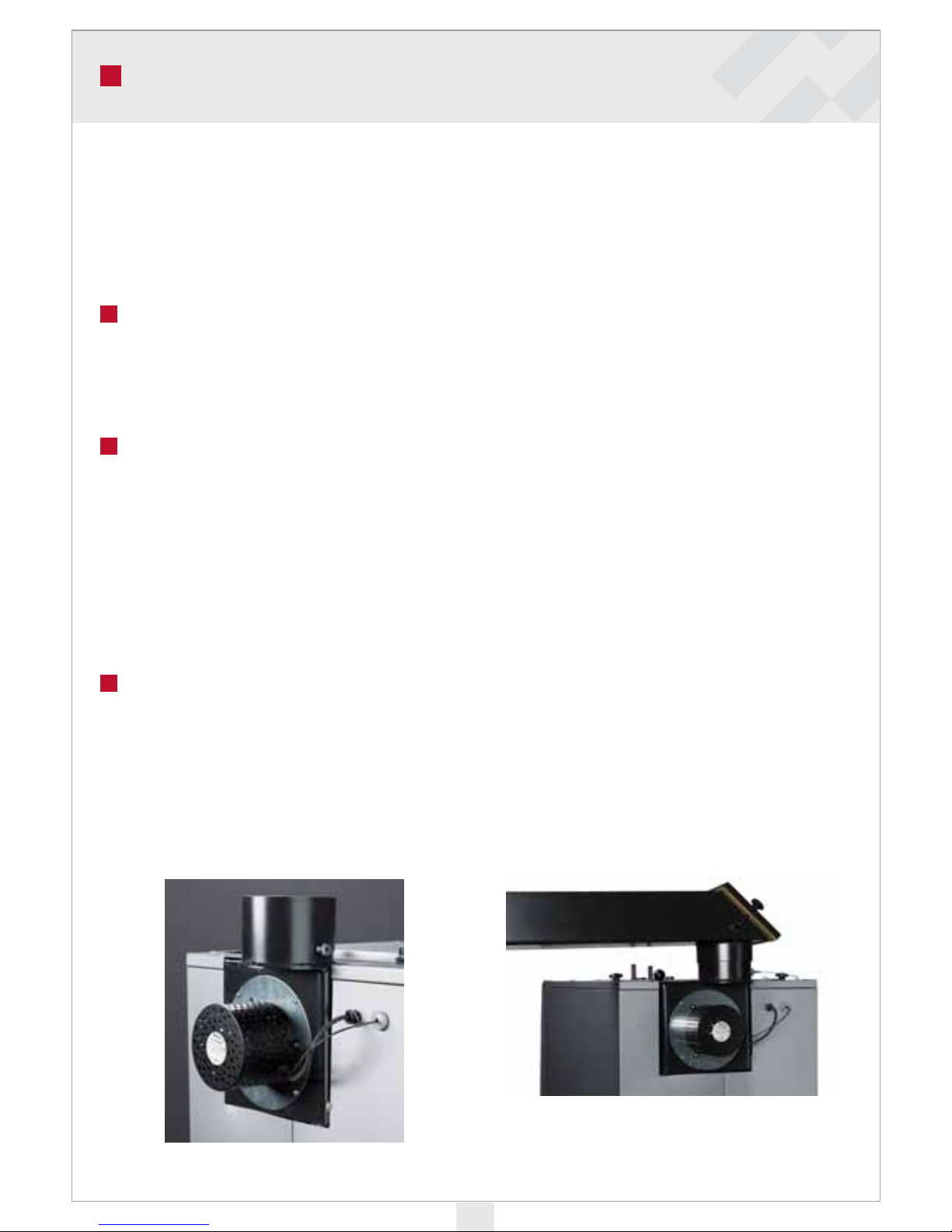
e Vedo has versatile assembly options that allow it to be fitted with different chimney solutions. e standard delivery always includes a flue gas fan. e standard connection to the
chimney is straight up (image 1). Make sure to leave enough space for cleaning when installing
the pipe. A chimney elbow piece also comes as a standard accessory. It allows the boiler to be
connected to a brick chimney (image 2).
Pic 1
Pic 2
Page 5

5
Plumbing connections
Before installation of the boiler, the heating system must be flushed and a water pressure test
carried out. e tightness of connections must be ensured after installation. e factory is not
responsible for damage caused by leaking connections.
Relief valve installation
e pressure relief valve must be CE-approved with a maximum opening pressure of 1.5 bar
and a minimum size of DN 15. It must correspond to the highest pressure class of the equipment assembly. Between the valve and the boiler, no equipment may be installed, the connection
of which could be closed. e exhaust pipe must be dimensioned and installed so that it neither
restricts the exhaust efficiency of the relief valve, nor causes a hazardous situation when the valve is working.
e capacity of the expansion vessel must correspond to the greatest possible fluid volume change in the boiler system. In periodic heating, the expansion capacity must be approximately 10%
of the system volume. We recommend that only a closed system is used (membrane expansion
vessel).
Filling the system
Before heat is turned on, the storage tank and heating system must be filled with water.
Instructions for lling
• Open all shutter valves, including the four-way mixing valve.
• e pump must be switched off. Fill in the heating system.
• Remove air through the accumulator and radiators.
• When the system is filled, you can switch on the circulation pump and start heating.
• When the water in the boiler has reached the set operating temperature, switch off the
pump and remove air from radiators again. is has to be repeated a few times.
Since there is a lot of air in the water at the start (up to 10%), it is normal for the pressure to
drop as air leaves the system. erefore it may be necessary to add water on several occasions
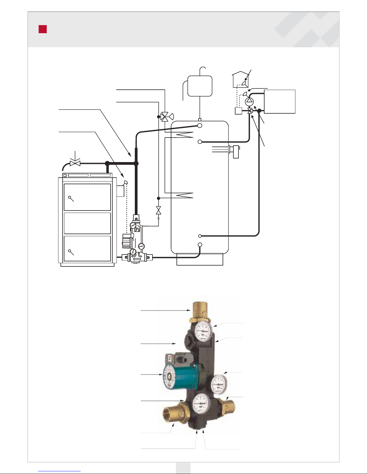
when operating the boiler. e temperature of water returning to the boiler should be around
70°C, which is achieved through a by-pass connection illustrated in the connection diagram.
A sufficiently high boiler temperature throughout the operation keeps the convection surfaces
clean and achieves highly efficient combustion. is also enables a long service life for the boiler,
since no corroding acids will form on the fire surfaces.
INSTALLATION
Page 6
6
CONNECTION DIAGRAM
A T-pipe with a min.
diameter of 1 ¼”
improves ventilation
Flue thermostat
Relief valve
Boiler
Hot water
Cold water
Mixer valve
Exp.
vessel
Automatic
shunt
Electric resistor
Warm water
accumulator
Tank
Room temperature sensor
Radiator temperature sensor
Filling
Radiator
Radiator pump
Shunt valve
Connection to boiler top
Ball check valve 1 ¼” IG
Internal thermal valve
Internal pump Wilo RS 25-6/3
Thermometer
Connection to accumulator
tank bottom
Automatic cycle valve
in case of power cut
Easy-to-clean dirt pocket to
prevent operating errors
Connection to boiler bottom
Thermometer
Filling connection R15
Ball check valve 1 ¼” IG
Thermometer
Ball check valve 1 ¼” IG
Page 7
7
TEMPERATURE CONTROL VALVE
e Ariterm Vedo boiler must be installed in connection with a warm water accumulator. is
improves its functionality and extends its life span substantially.
By installing the boiler as presented here, it is possible to make the boiler temperature rise
quickly and to maintain a steady, high temperature when the boiler is being used. e fact that
water is layered in the accumulator ensures a quick supply of warm water soon after heating
starts. e heating circuit and household water circuit are connected to the accumulator.
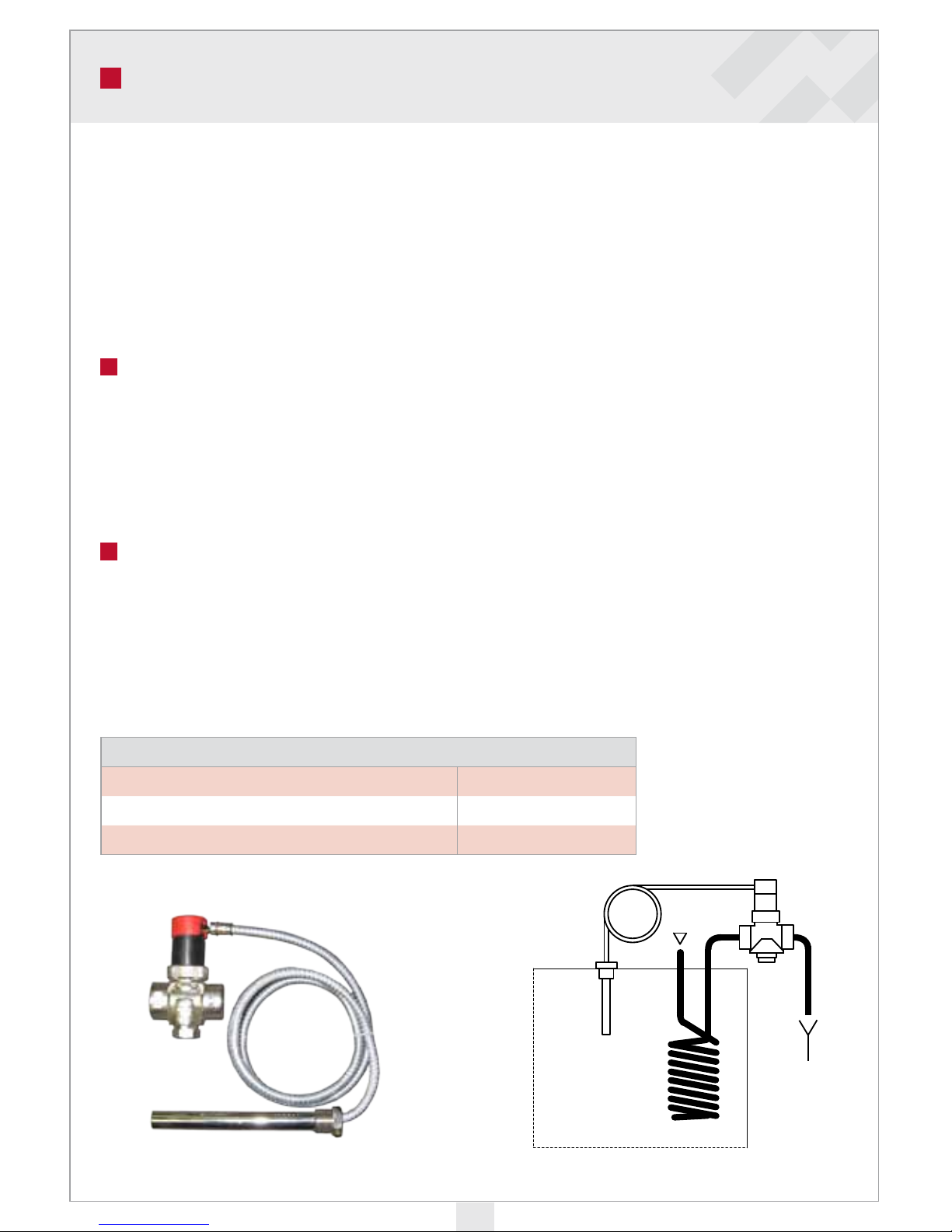
Installing a temperature control valve to wood-red boiler with a cooling spi-
ral
e Pressure Equipment Directive requires that manually-filled wood-fired boilers must be
equipped with a safety device, which prevents the boiler from overheating. We recommend the
SYR 3065 temperature control valve for this boiler. is does not, however, replace other safety
devices, such as a pressure relief valve.
Installation
e temperature control valve is connected to the cooling spiral so that, when the valve is activated, it sends hot water down the drain. e temperature sensor is installed on the sleeve on the
upper part of the boiler, using a DN 15 x 150 well.
TECHNICAL DATA
Max pressure of incoming water 10 bar
Opening temperature 97° C
Temperature control valves are available from Ariterm Product Number 5012921
Page 8

8
ABOUT BURNING WOOD
Before starting the boiler, check the following:
• Heating network and boiler are filled with water, pressure at least 0.5 bar
• If there is a smoke pipe damper, make sure that it is open
• e heat supply pump is switched on
• e accumulator or network valves are open
• e combustion air outlet is open
• e relief valve is in unhindered contact with the boiler and is in working order.
Firewood
Fresh firewood contains 80–90% water during the growing season and 70% in winter. Wood
must be allowed to dry before it can be combusted. It is best to fell the trees in winter when
their wood contains less water. It is important to cut firewood to the appropriate length for the
boiler’s combustion chamber. Good firewood should contain no more than 15-25% water. Raw
wood must be cut and split to a suitable size to allow it to dry well and fit in the firebox. If the
wood is from a small tree and not split, strips of bark should be removed lengthways. Large,
damp pieces of wood burn poorly and carbonise slowly. is causes a lot of tar and soot to form
in the boiler and burns inefficiently. You can check the water content of wood by weighing it.
Cut a test piece from freshly-cut wood. It is fit for combustion when its weight has decreased by
about 60%. If the fresh piece of wood weighs 1,000 g, it is fit for combustion when it weighs 400
g.
Burning
Wood is an organic material. Its combustible constituents are carbon and hydrogen. When
wood heats up, these constituents are released and gasify. If the burning process is efficient (with
sufficient primary and secondary air available), the combustion temperature rises sufficiently
high to cause clean burning. Wood also contains some minerals, which result in impurities. In
order to achieve good burning performance and energy production and as few polluting and
sooty emissions as possible, bear the following in mind: Dry firewood. e water must evaporate before the wood is fit for combustion. If the water content is too high, the combustion is
incomplete.
A sufficient supply of air and a sufficiently high temperature in the combustion chamber are
needed. Appropriate air flow is important. If the wood is damp, a lot of heat goes to waste.
Damp weather, a cold chimney pipe and insufficient cross-sectional flue surface area have a negative impact on the draft. A good supply of oxygen is required in the ignition stage to achieve a
good layer of charcoal and efficient combustion.
Page 9
9
OPERATION
The use of wood in the Ariterm Vedo
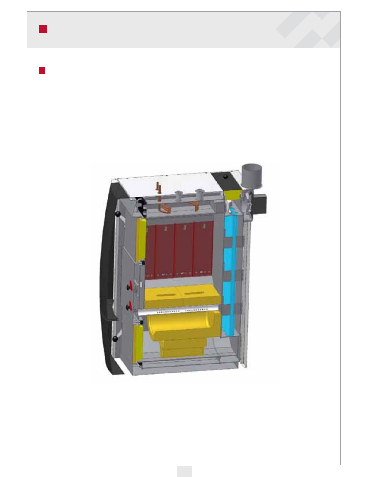
Ariterm Vedo is designed for the combustion of solid fuels in densely populated neighbourhoods. It has been tested and approved in accordance with the latest wood-fired boiler requirements. e approval requires both ceramic grates and transfer of heat into an accumulator.
Ariterm Vedo is a reverse combustion boiler in which combustion occurs downwards through
the ceramic grate.
Page 10
10
OPERATION
Starting the re:
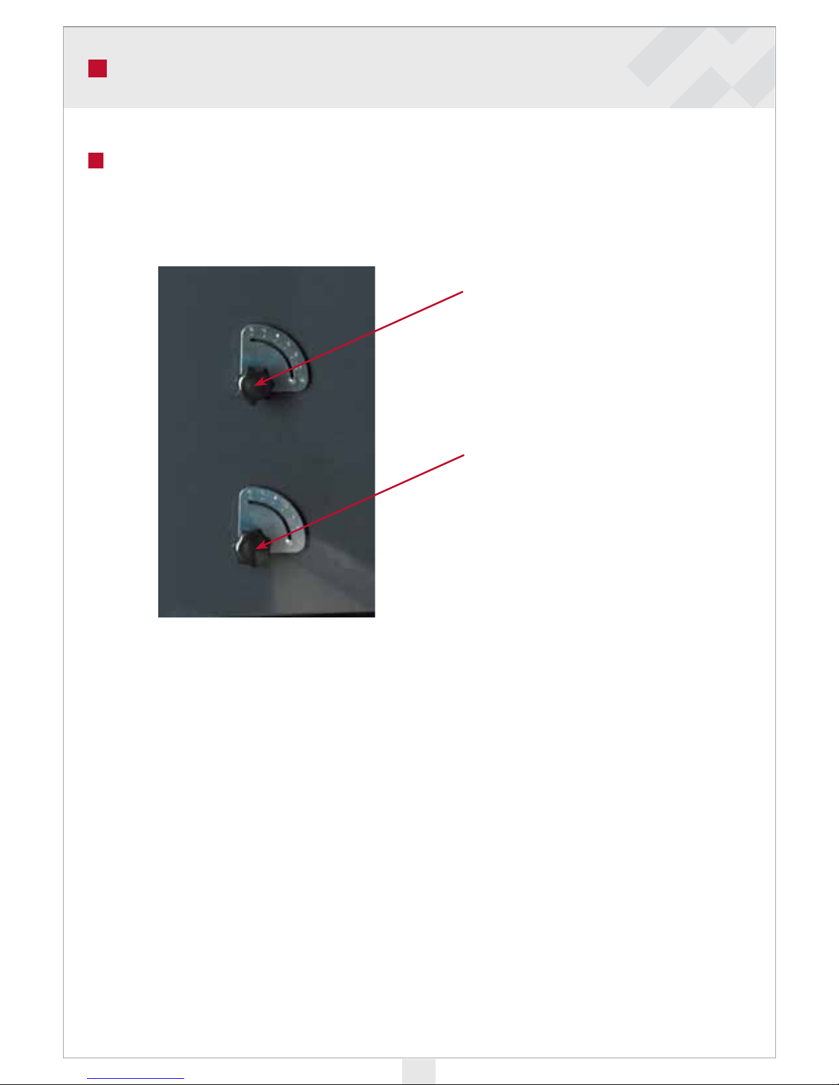
• Open the smoke pipe damper. Adjust primary air vent to 4 and secondary air vent to 5 (on
1 to 7 scale).
• Start up the exhaust fan.
• Open the feeding hatch, which causes the fire door damper to open automatically.
• Stack with small firewood, enough to cover the bottom of the chamber.
• Apply kindling on top of the wood. Start a fire.
• Close the feeding hatch.
• When the fire is properly burning and a layer of charcoal has formed, fill the firebox up no
higher than to the top of the air vents.
• After the fire is going well, adjust the secondary air vent approximately to position 2. Flue
gas temperature should be 150…180°C
Adjust primary air vent
to 4.
Adjust sekundary air
vent to 5.
Page 11

11
Adding rewood
Do not add firewood until after the first load has burnt down to a small amount of charcoal.
Open the feeding hatch slowly to avoid a cloud of smoke caused by the carbon monoxide that
may remain in the firebox. Add firewood. e amount of firewood should not be excessive so
that the accumulator can capture all the thermal energy released from the wood. e maximum
load of wood is to the top of the air vents.
Pellet use
Ariterm Vedo is compatible with an KMP PX21 pellet burner. Replace the stoking hatch with
a hatch with an PX21 pellet stoker. If you use a pellet burner, remove the ceramic grates and secondary combustion chamber and close primary and secondary air vents. Specified instructions
on the installation and use of the pellet burner come with the burner.
Oil use
Ariterm Vedo is also compatible with using oil as fuel. e oil burner is installed on the pellet
burner hatch using an oil burner flange, which is available as an accessory.
Electric use
e boiler is not compatible with electric use. If electric resistors are required, they should be
installed on the accumulator.
OPERATION
Page 12
12
SERVICE AND MAINTENANCE
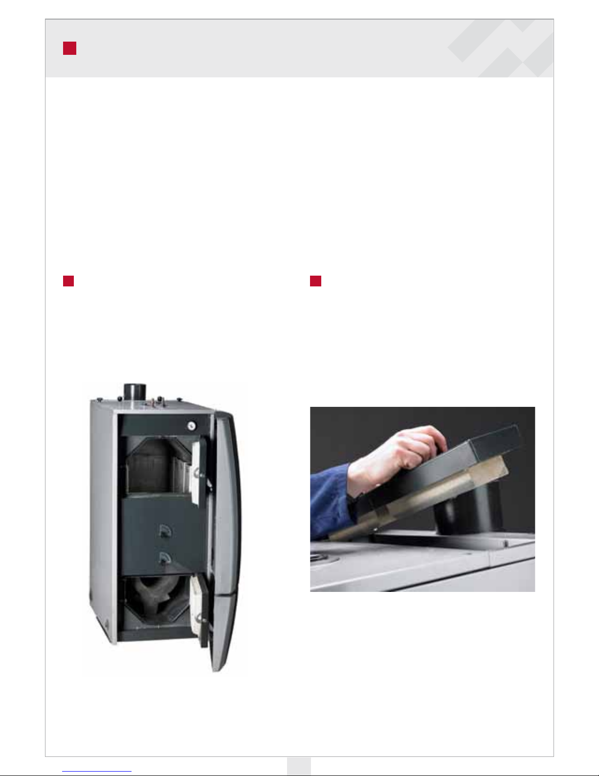
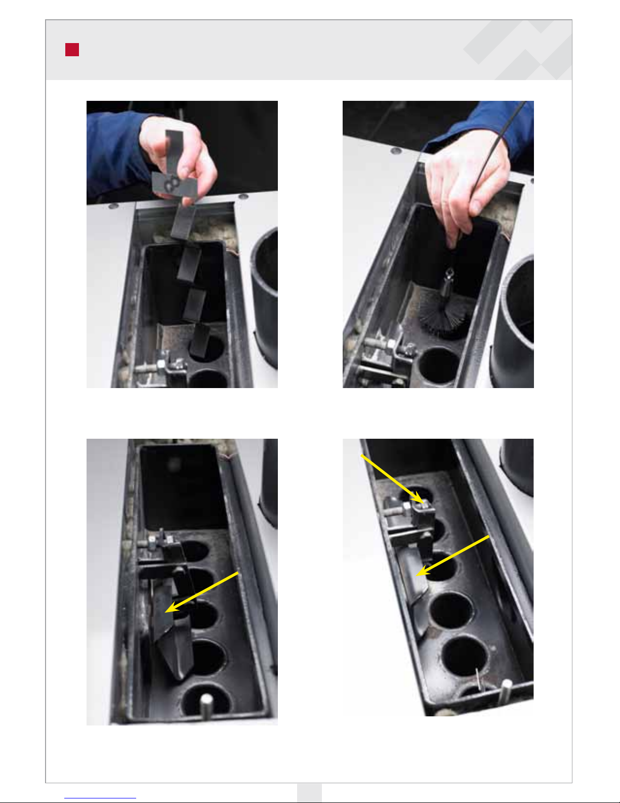
Also check and, if necessary, clean the blades
of the flue gas fan. Remove ash from the ceramic secondary combustion chamber through
the ash box door.
Open the convector cleaning door.
Before each heating season Once a week and as required in
the heating season
Check that the holes of the grate are unblocked
and that there is no combustion residue left
from previous use.
Always clean the convector after the flue gas
temperature has risen by 30°C from clean
boiler value, or the draft has weakened.
e boiler will function properly and have a long service life when the following matters are taken care of:
• e boiler should be located in a dry space.
• e boiler should always be operated within the recommended limits.
• e boiler should be cleaned up when the flue gas temperature has risen 20–30°C above
that of a clean boiler.
• If any part is damaged, it must be replaced with a new one as early as possible.
• Check that condensation water or water from pipe leaks cannot damage the boiler.
Page 13
13
SERVICE AND MAINTENANCE
Make sure that the fire door damper
opens and closes as you use the
feeding hatch.
Make sure that the fire door damper
closes when you close the feeding
hatch.
Remove all turbulators.
Clean the boiler convector by brushing
the convector pipes clean.
Page 14
14
From time to time, you should check that the
gap between the deflectors and the storage
chamber is unblocked. Lift the deflectors from
their supports to clean them. Also clean the
walls of the storage chamber.
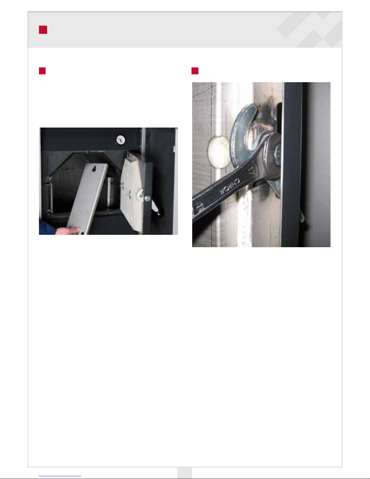
Other maintenance procedures Adjustment of the hatches
Check that the hatch sits tightly. A leaky feeding hatch will cause wood to combust in the
wrong place. Tighten the hatches by adjusting
the lock handle and hinge pieces.
The tightness of the hatches is important for
the proper functioning of the boiler.
Adjusting the lock handle:
• Unscrew the screw of the lock handle
enough to be able to turn the eccentric
sleeve in the hole.
• Turn the sleeve to make the handle move
away from the boiler. Tighten the screw
slightly.
• Test whether the hatch now sits more
tightly on the handle side.
SERVICE AND MAINTENANCE
Page 15
15
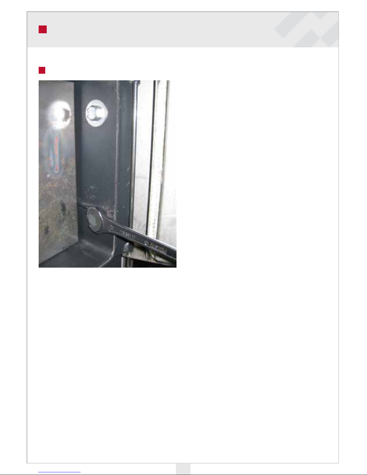
• Unscrew both mounting screws of the
hinge piece enough to move the hinge.
• Move the hinge piece slightly in the direction of the boiler.
• Tighten the mounting screws slightly and
test whether the hatch now sits more
tightly on the hinge side.
• Once the hatch is sitting properly, tighten
all the screws. If the adjustment tolerance
on the hatch runs out, its seal will have to
be replaced.
Adjusting the hinge:
SERVICE AND MAINTENANCE
Page 16
16
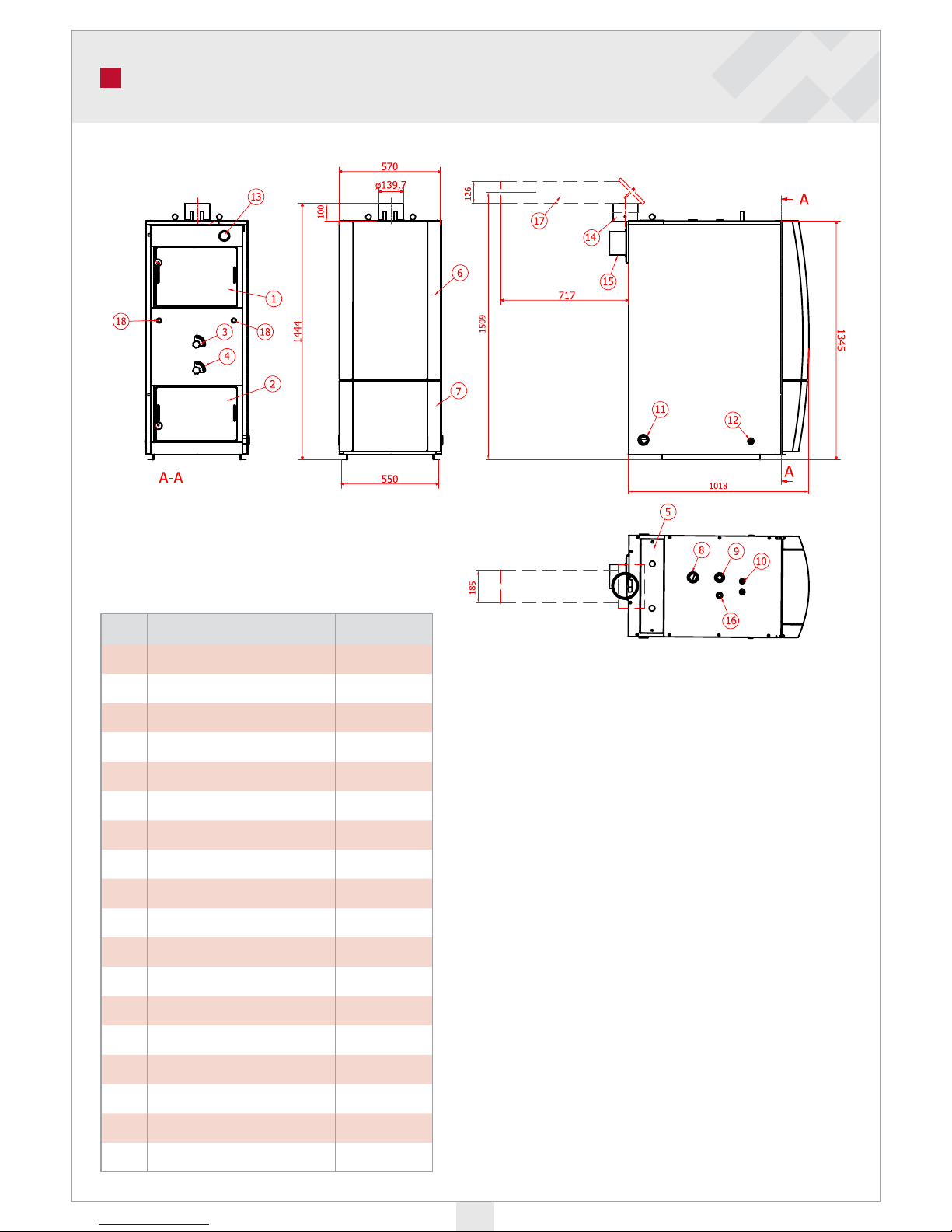
Part Name Unit
1 Feeding hatch
2 Stoking hatch
3
Primary air vent
4
Secondary air vent
5
Convector door
6
Top door
7
Bottom door
8
Outlet to accumulator DN 32
9
Expansion vessel outlet DN 25
10
Cooling spiral Cu 15
11
Return from accumulator DN 32
12
Draining outlet DN 15
13
Water thermometer / pressure gauge
14
Flue connection
15
Flue gas fan
16
Control valve DN 15
17
Horizontal flue pipe
18
Burnet thermostat / sensor assembly DN 15
MEASUREMENTS AND CONNECTIONS
Page 17
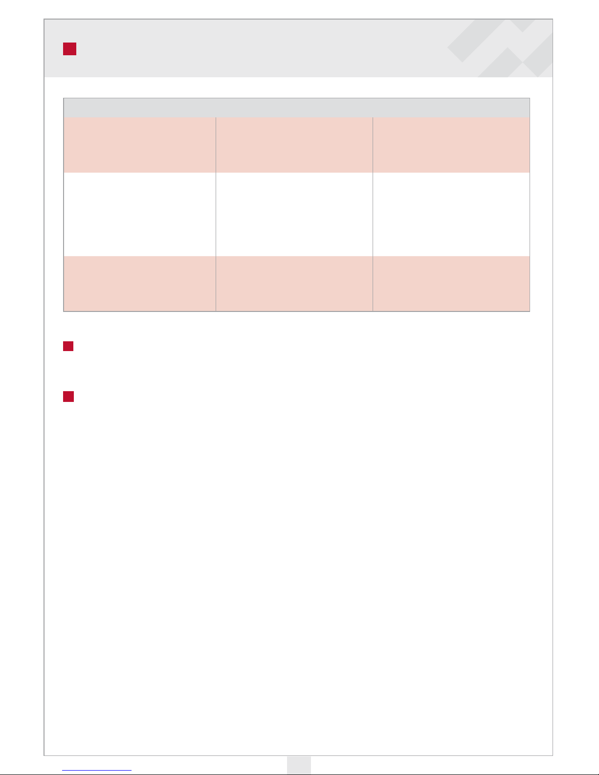
17
TECHNICAL DATA
TECHNICAL DATA
Capacity
With wood
With pellets
With oil
30 kW
30 kW
30 kW
Dimensions
Width
Depth
Height
Weight (empty)
Water capacity
Flue connection
570 mm
1016 mm
1345 mm
415 kg
125 L
diameter 140 mm (external)
Design values
Boiler pressure
Permitted boiler temperature
Size of warm water accumulator
Maximum length of firewood
0,5-1,5 bar
Max 20-120 °C
1100 – 2500 L
0,5 m
Guarantee
For Warranty Issues Ariterm Sweden AB refers to our local Distributor.
Removal from use
A boiler that has reached the end of its useful life can be used for scrap.
Page 18
18
General
A flue gas fan is a standard equipment for the Ariterm Vedo. e fan system includes a control
unit which runs the fan at a set speed during combustion periods.
When a combustion period is over, the fan stops automatically. e fan unit can also be preset
to work during pellet burning, in which case the rotating speed is set to alternate in line with
standby mode and active combustion cycles. e fan control unit can also be used to control the
warm water accumulator loading pump.
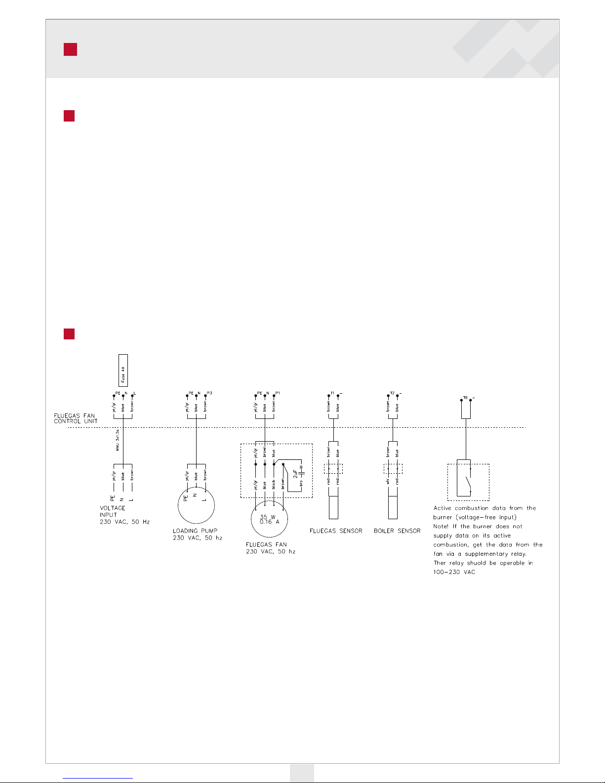
• Flue gas fan: 50W-300W, 1~/230VAC
• Warm water accumulator pump: 20W-300W, 1~/230VAC
FLUE GAS FAN CONTROL UNIT v091021
Electric installation
Page 19
19
P1
230 VAC
50Hz
T2
T1
P3
T6
2.
3.4.
1.
CONTENT OF DELIVERY AND INSTALLATION
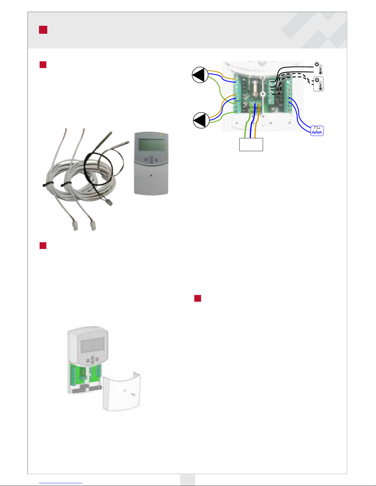
The delivery includes:
1. Control unit
2. Flue gas sensor
3. Boiler water sensor
4. Extension cable
Installation
It is preferable to place the control unit in
a location where no extension is required
for the cable of the flue gas or boiler water
sensors. The extension cable for flue gas and
boiler water sensor is 4 m long.
1. Remove control unit lid.
2. Fluegas fan, loading pump, temperature
sensors and 230 VAC voltage input are
connected to the terminal strips underneath the control unit lid.
P1=Flue gas fan
P3=Loading pump
T1=Flue gas sensor
T2=Boiler water sensor
T6=Active combustion alert from the pellet
burner (voltage-free input)
NOTE: If the pellet burner being used
cannot supply voltage-free contact data, this
data can be accessed from the pellet burner’s
flue gas fan via a supplementary relay. e
relay should be operable in the voltage area
100–230 VAC. e fan control unit input is
controlled by a normally open NO switch.
Operation mode Wood
When the fan is started in the wood burning mode, a delay period starts (factory
setting Fan delay time 15 minutes, can be
set between 3 and 15 minutes). During this
delay period, the left top corner of the screen
displays a figure that tells you how many
minutes are left of the delay period.
While the delay period lasts, the flue gas
temperature will rise above the setting temperature, and a flame icon will appear inside the
boiler icon on the screen. e fan will run for
as long as the flue gas temperature is above
this limit value (settings Fan temp. limit).
Page 20
20
OPERATING MODES AND MENUS
Towards the end of active combustion, the
temperature of the flow gases will start to
fall. When the temperature falls below the
limit temperature (factory setting 90 °C, can
be set between 70 and 150°C), the fan stops
automatically.
e factory setting for fan speed during
active combustion is 60%. e speed can be
adjusted between 0 and 100%.
Pellet use
If a pellet burner is in use, the fan control
unit can be set to monitor the status of the
burner (and not the flue gas temperature).
e pellet burner active combustion data
(must be voltage-free) is available at input
T6.
When the operating mode is set on Pellet, the
fan is continuously activated. When the pellet
burner is in standby mode, the fan rotates at
a lower speed, (Fan speed min). When the
burner goes into active combustion, the fan
starts rotating faster (Fan speed max).
User menus
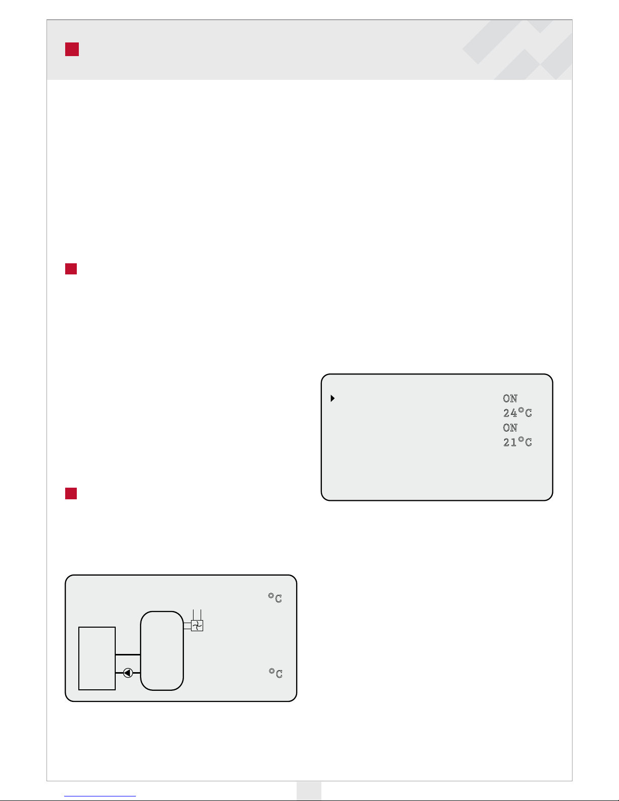
e basic screen displays images of the boiler
and the flue gas fan. When the fan is rotating,
the icon rotates as well. T1 indicates the flue
gas temperature.
If you have selected the flue gas fan, loading
pump function and boiler water sensor from
the Settings menu, the screen displays an
accumulator icon, a pump icon and the current boiler water temperature T2. When the
pump is running, the pump icon rotates.
In the sample view, the operating mode has
been set as Wood. e prompt ON (+) in the
top left corner of the screen means that the
flue gas fan should be turned on by pressing
the (+) button below the screen. When the
fan is running, the top left corner of the screen displays a figure that tells you how many
minutes are left of the start-up delay. During
that time, flue gas temperature should rise
over Fan temp. limit-settings. Move to control
unit menus from the main screen by pressing
the arrow to the right.
In this view you can switch off the fan while
the start-up delay continues, or prevent its
start.
You can also switch off the loading pump
here. For instance, if you want to switch off
the fan, scroll the right arrow to the text Fan
by pressing the + or – buttons. When you
have the arrow at the correct point, activate it
by pressing the ‘arrow right’ button. When the
line is activated, you can switch the setting to
OFF by pressing the + or - buttons.
Testing
Fan
Tank pump
T1
T2
55%
ON
30°C
22°C
Settings WOOD
Fan temp. limit
Fan / delay time
Fan speed
Tank pump starts
No
90°C
10min
55%
80°C
90°C
Settings PELLET
Fan speed / max
Fan speed / min
Pump temp. limit
50%
30%
70%
MENUES
Service
Settings
Testing
Fan
Smokegas temp
Tank pump
Boiler water
Menues
ON
24°C
ON
21°C
Service
Operation mode
Tank pump
Boiler t.sensor
English
WOOD
ON
ON
T1
T2
ON
T1
T2
22°C
27°C
(+)
0%
Testing
Fan
Tank pump
T1
T2
55%
ON
30°C
22°C
Settings WOOD
Fan temp. limit
Fan / delay time
Fan speed
Tank pump starts
No
90°C
10min
55%
80°C
90°C
Settings PELLET
Fan speed / max
Fan speed / min
Pump temp. limit
50%
30%
70%
MENUES
Service
Settings
Testing
Fan
Smokegas temp
Tank pump
Boiler water
Menues
ON
24°C
ON
21°C
Service
Operation mode
Tank pump
Boiler t.sensor
English
WOOD
ON
ON
Page 21
21
OPERATING MENUS
Even if the loading pump is switched ON, it
will not rotate if the boiler water temperature
is below the pump starting temperature (Setting- Tank pump start). You can test the fan
and pump operation in the Testing menu.
Select Menues and press the arrow right button to access the main menu, which has the
sub-menus Service, Settings and Testing
Move to the previous menu by pressing the
left arrow button. If no button has been
activated for one minute, the view returns to
the main screen.
Service - menu
e setting on the Service menu are important
as they are used to set the operating mode
Operation mode. e factory setting is burning wood Wood. When you want to operate
the fan through the pellet burner, select Pellet.
NOTE: e operating mode selection must
be done within a minute of switching the
control unit on.
When you want to use the Tank pump function, make sure the correct line is switched
ON. When this setting has been selected, the
main screen displays accumulator and pump
icons. e loading pump settings also appear
in the Settings menu. e boiler temperature
sensor can be switched on regardless of whether the loading pump is being used or not.
e bottom line of the Service menu displays
the language used. You can select from Finnish, Swedish and English.
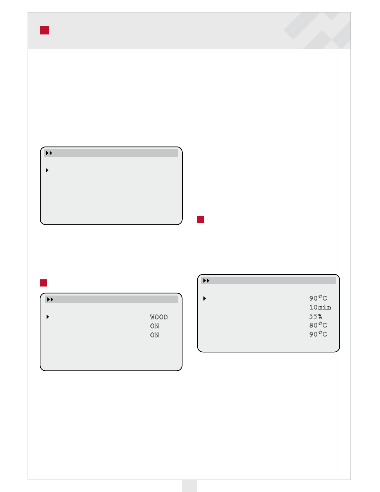
Settings menu (Wood burning
mode)
In time and temperature settings, one press
of the button adds one unit to the figure. For
faster resetting, keep the button pressed and
the figure will change faster.
When you have selected Wood in the Service
menu, the following are displayed in the
Settings menu:
Fan temp. limit determines the flue gas
temperature at which the fan switches off.
Factory setting 90 °C. This temperature can
be set between 70 and 150 °C. When flue gas
temperature is over that limit, fan will inn.
Settings WOOD
Fan temp. limit
Fan / delay time
Fan speed
Tank pump starts
No
90°C
10min
55%
80°C
90°C
MENUES
Service
Settings
Testing
Settings WOOD
Fan temp. limit
Fan / delay time
Fan speed
Tank pump starts
No
90°C
10min
55%
80°C
90°C
MENUES
Service
Settings
Testing
Service
Operation mode
Tank pump
Boiler t.sensor
English
WOOD
ON
ON
Settings WOOD
Fan temp. limit
Fan / delay time
Fan speed
Tank pump starts
No
90°C
10min
55%
80°C
90°C
Page 22
22
USER MENUS
Fan delay time: When the combustion period
is launched by pressing the + button, the
fan start-up delay begins. During this delay
period the flue gases should exceed the set
temperature Fan/Temp. limit. When the
temperature is above the limit, the fan will
run until the temperature drops below the
set value again. The factory set delay is 15
minutes. The delay can be set between 3 and
15 minutes.
Fan speed: This percentage value expresses
the fan rotating speed. It can be set between
0% and 100%.
Tank pump start: When the loading pump
has been activated in the Service menu, you
can set the boiler water temperature at which
the loading pump switches on. When the
temperature drops 5 °C below this, the pump
stops. If the pump has not been on for the
past 48 hours, run it for 10 seconds.
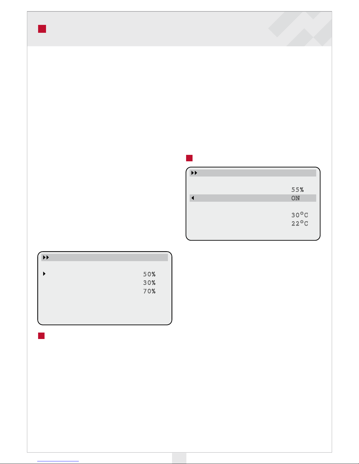
Settings menu (Pellet use)
When you have selected the Pellet mode from
the Service menu, you can adjust two rotating
speed settings in the Settings menu.
NOTE: e operating mode selection must
be done within a minute of switching the
control unit on.
In the pellet operating mode, the fan is always
running. When the burner is in standby
mode, the fan uses the lower set value Fan
speed / min. When the burner switches to
active combustion mode, the fan starts rotating faster (Fan speed / max) and a flame icon
appears on the main screen inside the boiler
icon. When the pellet burner switches back
to the standby mode, the fan rotation speed
falls back to slower pace. Pump temp. limit-
setting is same as Tank pump start.
Testing menu
e Testing menu can be used to test the fan
and loading pump operation when using the
boiler for the first time. e fan speed can
be adjusted between 20% and 100%. If the
setting is at 20% and further reduced, the fan
will stop.
T1 signifies the temperature measured by
the flue gas sensor and T2 that of the boiler
water sensor.
NOTE: Tank pump and T2 lines are not
visible on the screen if these have not been
activated in the Service menu.
Testing
Fan
Tank pump
T1
T2
55%
ON
30°C
22°C
Settings WOOD
Fan temp. limit
Fan / delay time
Fan speed
Tank pump starts
No
90°C
10min
55%
80°C
90°C
Settings PELLET
Fan speed / max
Fan speed / min
Pump temp. limit
50%
30%
70%
MENUES
Service
Settings
Testing
Testing
Fan
Tank pump
T1
T2
55%
ON
30°C
22°C
Settings WOOD
Fan temp. limit
Fan / delay time
Fan speed
Tank pump starts
No
90°C
10min
55%
80°C
90°C
Page 23
23
MANUFACTURES DECLARATION
Page 24

24
NOTES
Page 25

25
NOTES
Page 26

NOTES
Page 27

27
NOTES
Page 28
26.07.2010
- All Rights to modifications and corrections reserved.
ARITERM SWEDEN AB | Flottiljvägen 15
39241 Kalmar | www.ariterm.se | 0771-442850
 Loading...