


ARISTON 7HKRC 640 B RU-HA, 7HKRC 640 X RU-HA, 7HKRC 631 T RU-HA, 7HKRC 641 D X RU-HA, 7HKRC 641 D B RU-HA User Manual [ru]
...Operating Instructions
HOB
|
|
|
|
|
|
|
|
|
|
|
|
|
|
|
|
|
|
|
|
|
|
Contents |
GB |
|
|
|
|
|
|
|
|
|
|
|
|
|
|
WARNING, 2 |
|
|
GB |
|
|
RS |
|
|
|
|
|
|
|
Installation, 3-5 |
|
||
|
|
|
|
|
|
|
|
English,1 |
Русский, 14 |
|
|||||
Positioning |
|
||||||
|
|
|
|
|
|
|
|
|
|
|
|
|
|
Electrical connection |
|
|
|
|
|
|
|
Description of the appliance, 6-7 |
|
|
|
|
|
|
|
Control panel |
|
|
|
|
|
|
|
Extendable cooking zones |
|
7HKRC 640 B RU/HA 7HKRC 640 X RU/HA 7HKRC 631 T RU/HA 7HKRC 641 D X RU/HA 7HKRC 641 D B RU/HA
RC 640 IRFH S
RC 631 TIRFH S
RC 641 DBRFH S
Start-up and use, 8-11
Switching on the hob Switching on the cooking zones Switching off the cooking zones Power function
Heating elements
Programming the cooking duration Timer
Control panel lock Switching off the hob “Demo” mode
Practical advice on using the appliance Safety devices
Practical cooking advice
Precautions and tips, 12
General safety
Disposal
Care and maintenance, 13
Switching the appliance off
Cleaning the appliance
Disassembling the hob
Technical description of the models, 13

WARNING!
|
|
|
|
GB |
• WARNING: The appliance and |
|
|
|
its accessible parts become hot |
|
during use. |
|
• Care should be taken to avoid |
|
touching heating elements. |
|
• Children less than 8 years of |
|
age shall be kept away unless |
|
continuously supervised. |
|
• This appliance can be used by |
|
children aged from 8 years and |
|
above and persons with reduced |
|
physical, sensory or mental |
|
capabilities or lack of experience |
|
and knowledge if they have been |
|
given supervision or instruction |
|
concerning use of the appliance |
|
in a safe way and understand the |
|
hazards involved. Children shall not |
|
play with the appliance. Cleaning |
|
and user maintenance shall not |
|
be made by children without |
|
supervision. |
|
• WARNING: Unattended cooking |
|
on a hob with fat or oil can be |
|
dangerous and may result in fire. |
|
• NEVER try to extinguish a fire with |
|
water, but switch off the appliance |
|
and then cover flame e.g. with a lid |
|
or a fire blanket. |
|
• WARNING: Danger of fire: do |
|
not store items on the cooking |
|
surfaces. |
|
• WARNING: If the surface in glass- |
|
ceramic is cracked, switch off the |
|
appliance to avoid the possibility of |
|
electric shock. |
|
•Never use steam cleaners |
|
or pressure cleaners on the |
|
appliance. |
|
•The appliance is not intended to be |
|
operated by means of an external |
|
timer or separate remote control |
|
system. |
2

Installation
!Before operating your new appliance please read this instruction booklet carefully. It contains important information concerning the safe operation, installation and maintenance of the appliance.
!Please keep these operating instructions for future reference. Pass them on to any new owners of the appliance.
Positioning
!Keep all packaging material out of the reach of children. It may present a choking or suffocation hazard (see Precautions and tips).
!The appliance must be installed by a qualified professional in accordance with the instructions provided. Incorrect installation may cause harm to people and animals or may damage property.
Built-in appliance
Use a suitable cabinet to ensure that the appliance functions properly.
•The supporting surface must be heat-resistant up to a temperature of approximately 100°C.
•If the appliance is to be installed above an oven, the oven must be equipped with a forced ventilation cooling system.
•Avoid installing the hob above a dishwasher: if this cannot be avoided, place a waterproof separation device between the two appliances.
•Depending on the hob you want to install, the cabinet must have the following dimensions (see figure):
|
|
|
590 |
|
|
|
574 |
|
|
|
|
|
|
|
|
|
|
48 |
|
|
|
520 |
48 |
|
|
|
|
|
|
|
|
|
|
504 |
|
|
|
|
|
|
|
|
|
|
|
|
|
|
1 |
|
|
|
|
|
|
|
|
- |
|
|
|
- |
|
|
|
|
+/ |
|
|
|
|
560 |
|
|
|
|
|
|
|
1 |
- |
|
490 |
|
560 |
|
|
+/ |
|
|
+/ |
1 |
|
|
|
+/- |
490 |
|
|
|
|
|
|
|
|||
|
|
|
|
|
|
1 |
|
|
Ventilation
To allow adequate ventilation and to avoid overheating of the surrounding surfaces the hob should be positioned as follows:
•At a minimum distance of 40 mm from the back panel.
•So that a minimum distance of 20 mm is maintained between the installation cavity and the cabinet underneath.
•Kitchen cabinets adjacent to the appliance and taller than the top of the hob must be at least 600 mm
from the edge of the hob.
GB
min. 20 mm
mm5  COMPARTMENT
min. 40 mm
min. 20 mm |
5 mm |
FAN-ASSISTED |
OVEN |
min. 40 mm |
FRONT SIDE
OF HOB
SUPPORTING |
|
|
SURFACE |
30 |
|
|
40 |
UNDERSIDE
OF HOB
3
Fixing
GB The appliance must be installed on a perfectly level supporting surface.
Any deformities caused by improper fixing could affect the features and operation of the hob.
The thickness of the supporting surface should be taken into account when choosing the length of the screws for the fixing hooks:
•30 mm thick: 17.5 mm screws
•40 mm thick: 7.5 mm screws
Fix the hob as follows:
1.Use short flat-bottomed screws to fix the 4 alignment springs in the holes provided at the central point of each side of the hob.
2.Place the hob in the cavity, make sure it is in a central position and push down on the whole perimeter until the hob is stuck to the supporting surface.
3.For hobs with raised sides: After inserting the hob into its cavity, insert the 4 fixing hooks (each has its own pin) into the lower edges of the hob, using the long pointed screws to fix them in place, until the glass is stuck to the supporting surface.
!The screws for the alignment springs must remain accessible.
!In order to adhere to safety standards, the appliance must not come into contact with electrical parts once it has been installed.
!All parts which ensure the safe operation of the appliance must not be removable without the aid of a tool.
Electrical connection
! The electrical connection for the hob and for any builtin oven must be carried out separately, both for safety purposes and to make extracting the oven easier.
Terminal board
On the lower part of the appliance there is a connection box for the different types of electricity supply (the
picture is only an indication and
is not an exact representation of the purchased model).
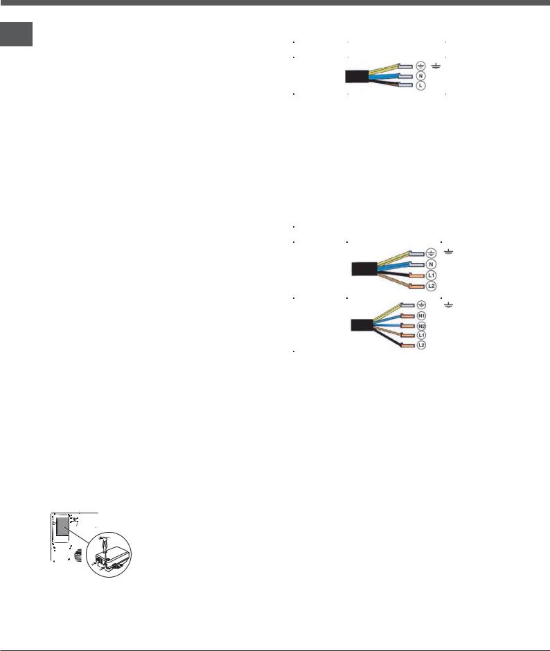
Single-phase connection
The hob is equipped with a pre-connected electricity supply cable, which is designed for single-phase
connection. Connect the wires in accordance with the instructions given in the following table and diagrams:
Voltage and |
Electrical cable |
Wire connection |
|
mains frequency |
|||
|
|
||
|
|
|
|
230-240V 1+N ~ |
|
: yellow/green |
|
|
N: the two blue wires together |
||
220-240V 1+N ~ |
|
||
|
L: brown and black together |
||
50/60 Hz |
|
||
|
|
|
Other types of connection
If the mains supply corresponds with one of the following:
Voltage and mains frequency
•400V - 2+N ~ 50/60 Hz
•220-240V 3 ~ 50/60 Hz
•230-240V 3 ~ 50/60 Hz
•400V - 2+2N ~ 50/60 Hz
Separate the wires and connect them in accordance with the instructions given in the following table and diagrams:
Voltage and |
Electrical cable |
Wire connection |
|
mains frequency |
|||
|
|
||
400V - 2+N ~ |
|
: yellow/green; |
|
|
|
||
50/60 Hz |
|
N: the two blue wires |
|
|
|
||
230-240V 3 ~ |
|
together |
|
220-240V 3 ~ |
|
L1: black |
|
50/60 Hz |
|
L2: brown |
|
|
|
|
|
|
|
: yellow/green; |
|
400V - 2+2N ~ |
|
N1: blue |
|
50/60 Hz |
|
N2: blue |
|
|
|
L1: black |
|
|
|
L2: brown |
|
|
|
|
If the mains supply corresponds with one of the following:
Voltage and mains frequency
• 400V 3 - N ~ 50/60 Hz proceed as follows:
! The cable provided is not suitable for the following types of installation.
1.Use a suitable supply cable, H05RR-F or higher, with the right dimensions (cable cross section: 25 mm).
2.To open the terminal board, use a screwdriver as
a lever under the side tabs of the cover (see Terminal board picture).
3.Loosen the cable clamp screw and the terminal board screws in accordance with the type of connection required and position the connection supports as shown in the following table and diagrams.
4.Position the wires in accordance with the information given in the following table and diagrams and connect the appliance by tightening all the screws for the springs as much as possible.
4
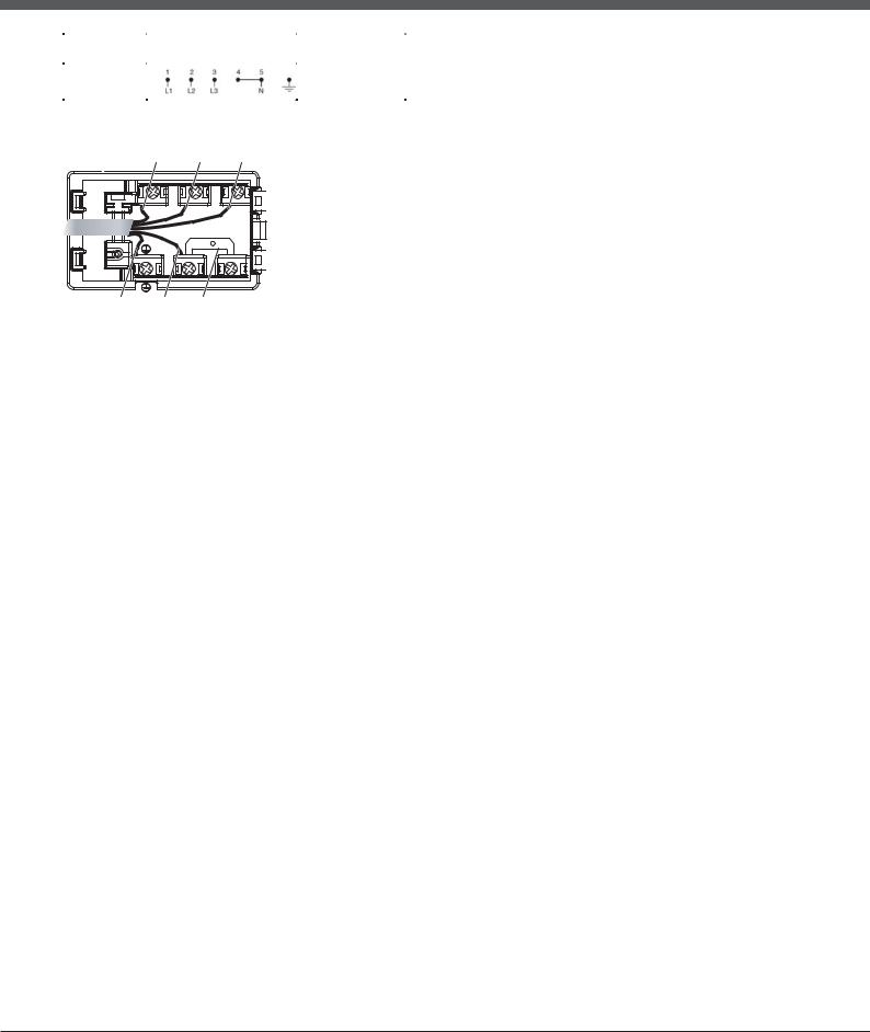
Voltage and |
Electrical connections |
Terminal board |
mains frequency |
||
|
|
|
400V 3-N ~ |
|
Three-phase 400 |
50/60 Hz |
|
|
|
|
|
|
|
|
5. Secure the power supply cable by fastening the cable clamp screw, then put the cover back on.
|
Phase |
Phase |
Phase |
|
|
1 |
2 |
3 |
Three-phase 400 |
|
|
5 |
4 |
|
Earth |
Neutral |
U-bolt |
|
|
|
|
connection support |
|
|
Connecting the electricity supply cable to the mains
If the appliance is being connected directly to the electricity mains an omnipolar switch must be installed with a minimum opening of 3 mm between contacts.
! The installer must ensure that the correct electrical connection has been made and that it is fully compliant with safety regulations.
Before connecting the appliance to the power supply, make sure that:
•The appliance is earthed and the plug is compliant with the law.
|
|
|
|
|
|
• The socket can withstand the maximum power of |
|
||||
GB |
|||||
the appliance, which is indicated on the data plate |
|||||
located on the appliance itself. |
|
||||
|
|||||
•The voltage falls within the range of values indicated on the data plate.
•The socket is compatible with the plug of the appliance. If the socket is incompatible with the plug, ask an authorised technician to replace it. Do not use extension cords or multiple sockets.
!Once the appliance has been installed, the power supply cable and the electrical socket must be easily accessible.
!The cable must not be bent or compressed.
!The cable must be checked regularly and replaced by authorised technicians only.
!The manufacturer declines any liability should these safety measures not be observed.
!Do not remove or replace the power supply cable for any reason. Its removal or replacement will void the warranty and the CE marking. INDESIT does not assume liability for accidents or damage arising from replacement/removal of the original power supply cable. Replacement can only be accepted when carried out by personnel authorised by INDESIT and using an original spare part.
5
Description of the appliance
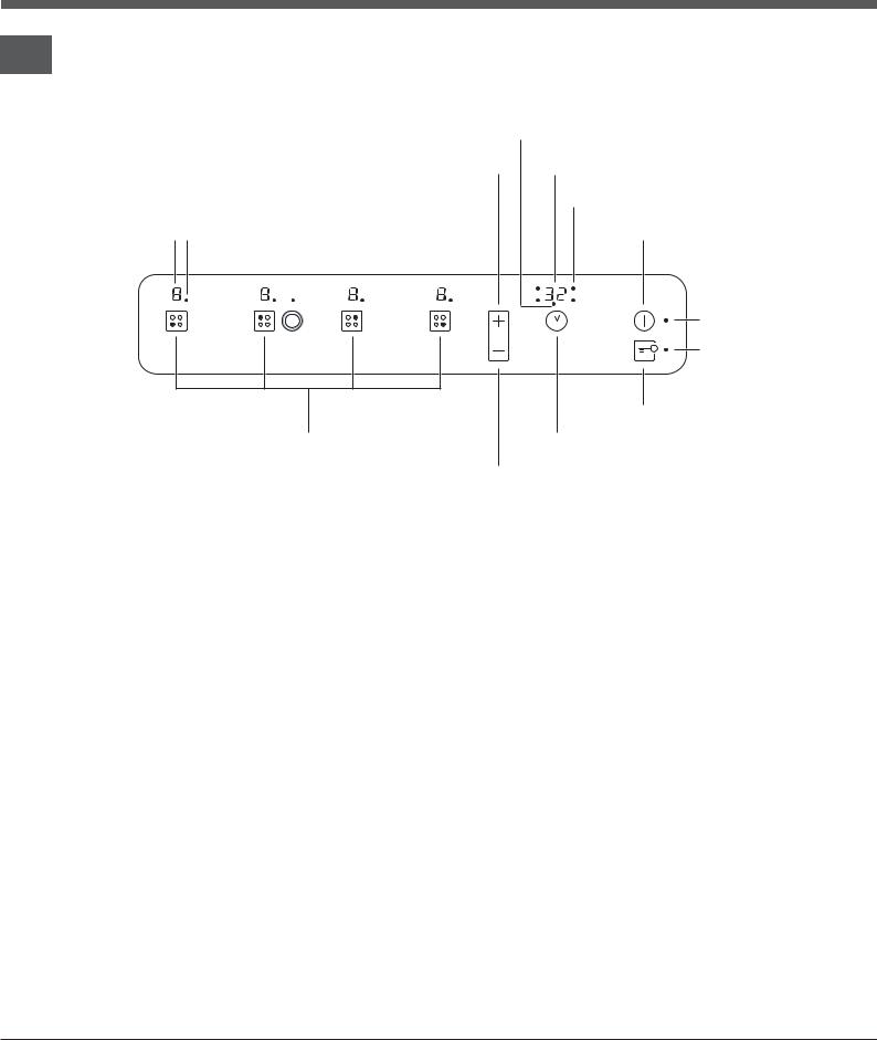
Control panel
GB
The control panel described in this manual is only a representative example: it may not exactly match the panel on your appliance.
|
|
TIMER* |
|
|
|
indicator light |
|
|
INCREASE |
PROGRAMME TIMER* |
|
|
POWER button |
display |
|
|
|
COOKING ZONE PROGRAMMED* |
|
|
|
indicator light |
|
POWER and COOKING ZONE |
ON/OFF |
||
RESIDUAL HEAT |
SELECTED indicator light |
button |
|
indicators |
|||
|
|
||
|
|
ON/OFF |
|
|
|
indicator light |
|
|
|
CONTROLS LOCKED |
|
|
|
indicator light |
|
|
|
CONTROL PANEL |
|
|
|
LOCK button |
|
|
COOKING ZONE |
PROGRAMME |
|
|
SELECTOR buttons |
TIMER* button |
|
REDUCE POWER button
•INCREASE POWER button switches on the hotplate and controls the power (see Start-up and use).
•REDUCE POWER button controls the power and switches off the hotplate (see Start-up and use).
•COOKING ZONE SELECTOR button shows a particular cooking zone has been selected and therefore various adjustments are possible.
•COOKING ZONE SELECTOR button is used to select the desired cooking zone.
•POWER indicator provides a visual display for the current heat level.
•ON/OFF button switches the appliance on and off.
•ON/OFF indicator light shows whether the appliance is on or off.
•PROGRAMME TIMER* button controls the cooking programme times (see Start-up and use).
*Only available in certain models.
•PROGRAMME TIMER* display shows which programme has been selected (see Start-up and use).
•COOKING ZONE PROGRAMMED* indicator lights show which cooking zones are being used during a cooking programme (see Start-up and use).
•CONTROL PANEL LOCK button prevents accidental changes to the hob settings (see Start-up and use).
•CONTROL PANEL LOCK indicator light shows the control panel has been locked (see Start-up and use).
•TIMER* indicator light shows that the timer has been activated
! This product complies with the requirements of the latest European Directive on the limitation of power consumption of the standby mode.
If no operations are carried out for a period of 2 minutes, after the residual heat indicator lights turn off and the fan stops (if present), the appliance automatically switches to the “off mode”.
The appliance resumes the operating mode once the ON/OFF button is pressed.
6
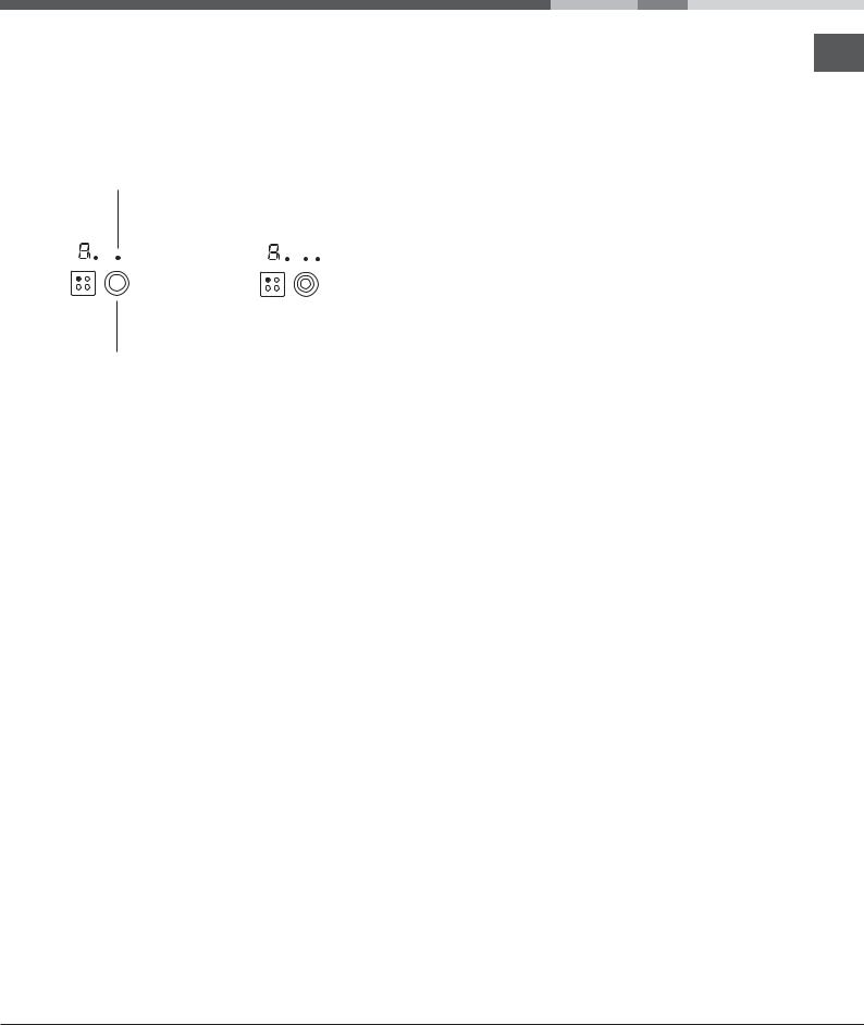
Extendable cooking zones
GB
Certain models are fitted with extendable cooking zones. A list of controls is given below (these controls are only present in models with the extendable cooking zone option).
Circular extendable hotplate
DOUBLE |
|
|
|
TRIPLE |
|||
|
|
|
|||||
|
|
|
|
|
|||
HOTPLATE ON |
|
|
|
HOTPLATE ON |
|||
|
|
|
|
|
|||
indicator light |
|
|
|
indicator light |
|||
|
|
|
|
|
|||
|
|
|
|
|
|
|
|
DOUBLE |
TRIPLE |
HOTPLATE ON |
HOTPLATE ON |
button |
button |
•DOUBLE HOTPLATE ON button switches on the double hotplate (see Start-up and use).
•DOUBLE HOTPLATE ON indicator light shows the double hotplate has been switched on.
•TRIPLE HOTPLATE ON button switches on the triple hotplate (see Start-up and use).
•TRIPLE HOTPLATE ON indicator light shows the triple hotplate has been switched on.
7

Start-up and use
!The glue applied on the gaskets leaves traces of GB grease on the glass. Before using the appliance, we
recommend you remove these with a special nonabrasive cleaning product. During the first few hours of use there may be a smell of rubber which will disappear very quickly.
!A few seconds after the hob is connected to the electricity supply, a buzzer will sound. The hob may now be switched on.
!If the -or +button is pressed for an extended period of time, the display scrolls quickly though the power levels and timer minutes.
Switching on the hob
To switch the hob on, press and hold the  button for approximately one second.
Switching on the cooking zones
Each cooking zone is controlled using a selector button  and a power adjustment device consisting of a
double -and +button.
•To begin operating a cooking zone, press the
corresponding control button and set the desired power level (between 0 and 9) using the buttons - and +.
Power function
The power function for the cooking zones may be used to shorten heating-up times. Activate and set the power
level for the desired cooking zone  as described in the previous paragraph. Press and hold the selector
button corresponding to the desired cooking zone for at least 2 seconds. The display, the power level indicator, will alternately show the letter “P” and the power level set previously until the desired power level has been reached. Once this level has been reached, the display will revert to showing the set power level. To deactivate this function, press and hold – for at least 2 seconds - the selector button corresponding to
the cooking zone on which the function has been activated; alternatively, select a different power level
using the buttons -and +.
Switching off the cooking zones
To switch off a cooking zone, select it using the
corresponding selector button  and:
and:
• Press the -button: the power of the cooking zone will progressively decrease until it is switched off.
Heating elements
Two types of heating element may be installed, depending on the appliance model: halogen and radiant elements.
Halogen elements emit heat via radiation from the halogen lamps they contain.
They have similar properties to gas burners: they are easy to control and reach set temperatures quickly, allowing you to see the power level instantly. Radiant elements consist of a series of coils which allow heat to be distributed evenly at the base of the cookware, so that all slow-flame cooking may be
performed successfully, for example stews, sauces or reheated dishes.
Programming the cooking duration
! All the cooking zones may be programmed simultaneously, for a duration between 1 and 99 minutes.
1.Select the cooking zone using the corresponding selector button.
2.Adjust the power level of the cooking zone.
3.Press the  programming button. The indicator light corresponding to the selected zone will start flashing.
4.Set the cooking duration using the -and + buttons.
5.Confirm by pressing the  button or automatic selection occurs after 10 seconds.
The timer begins counting down immediately. A buzzer sounds for approximately 1 minute and the cooking zone switches off when the set programme has finished. Repeat the above procedure for each hotplate you wish to programme.
Using multiple programmes and the display
If one or more hotplates are programmed, the display will show the data for the hotplate with the least time remaining, and the light corresponding to the position of the hotplate will flash.
8
The lights corresponding to the other hotplates programmed will be switched on.
To visualise the time remaining for the other programmed
hotplates, press the |
button repeatedly: the time |
|
||||
remaining for each hotplate will be |
|
|
||||
|
|
|
|
|
||
shown sequentially in a clockwise order, |
|
|
|
|
||
|
|
|
||||
starting from the front left hotplate. |
|
|
|
|
|
|
|
|
|
|
|||
|
|
|
|
|||
|
|
|
|
|
|
|
Changing the programme
1.Press the  button repeatedly until the duration you wish to change is shown.
2.Use the  buttons to set the new duration.
3.Confirm by pressing the  button.
To cancel a programme, follow the above instructions.
At step 2, press the -button: the duration decreases progressively until it reaches 0 and switches off. The programme resets and the display exits programming mode.
Timer
The hob must be switched on.
The timer can be used to set a duration up to 99 minutes.
1. Press the  programming button until the timer
 .
.
2. Set the desired duration using the -and +buttons.
3. Confirm by pressing the  button.
The timer begins counting down immediately. When the time has elapsed, a buzzer will sound (for one minute).
Control panel lock
When the hob is switched on, it is possible to lock the oven controls in order to avoid accidental changes being made to the settings (by children, during
cleaning, etc.). Press the  button to lock the control panel: the indicator light above the button will switch on.
To use any of the controls (e.g. to stop cooking), you
must switch off this function. Press the button for a few moments, the indicator light will switch off and the lock function will be removed.
Switching off the hob
GB
Press the  button to switch the appliance off. If the control panel lock has been activated, the
controls will continue to be locked even after the hob is switched on again. In order to switch the hob on again, you must first remove the lock function.
“Demo” mode
It is possible to set the hob to a demonstration mode where all the controls work normally but the heating elements do not switch on. To activate the “demo” mode the hob must be switched on, with all the hotplates switched off.
•Press and hold the +and -buttons simultaneously for 6 seconds. When the 6 seconds have elapsed, the ON/OFF and CONTROLS
LOCKED indicator lights will flash for one second. Release the +and -buttons and press the  button;
•The display will show the text DE and MO and the hob will be switched off.
•When the hob is switched on again it will be set to the “demo” mode.
To exit this mode, follow the procedure described above. The display will show the text DE and OF and the hob will be switched off. When it is next switched on, the hob will function normally.
Practical advice on using the appliance
To obtain the best results from your hob:
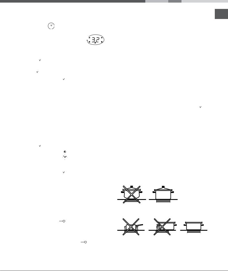
•Use pans with a thick, flat base in order to fully utilise the cooking zone.
•Always use pans with a diameter which is large enough to cover the hotplate fully, in order to use all the available heat.
•Make sure that the base of the cookware is always clean and dry, in order to fully utilise and extend the life of both the cooking zones and the cookware.
•Avoid using the same cookware which has been used on gas burners: the heat concentration on gas burners may distort the base of the pan, causing it not to adhere correctly.
9
 Loading...