

Servicing
Instructions
Type CBoilers
G.C.N: 47-116-16
LEAVE THESE INSTRUCTIONS
WITH THE END-USER
Country of destination: GB

2
1. SERVICING INSTRUCTIONS
1.1 REPLACEMENT OF PARTS
1.2 TO GAIN GENERAL ACCESS
- Removing the front panel
- Removing the sealed chamber front cover
- Removing the side panels
1.3 ACCESS TO THE COMBUSTION CHAMBER
- Removing the combustion cover
- Removing the burner and jets
- Removing the electrodes
- Removing the heat exchanger
- Removing the air pressure switch
- Removing the fan
- Removing the venturi device
1.4 SERVICING AND REMOVAL OF THE GAS VALVE
- Setting the gas pressures
- Removing the spark generator
- Removing the gas valve
1.5 ACCESS TO THE WATER CIRCUIT
- Removing the pump pressure switch
- Removing the safety valve
- Removing the automatic air vent
- Removing the pump
- Removing the pressure gauge
- Removing the expansion vessel
- Removing the overheat thermostat
- Removing the heating temperature sensor (N.T.C.)
- Removing the D.H.W. temperature sensor (N.T.C.)
- Removing the diverter valve microswitch
- Removing the diverter valve
1.6 ACCESS TO THE CONTROL SYSTEM
- Checking the fuses
- Removing the time clock
- Removing the P.C.B.
2. FAULT FINDING
2.1 FAUL T FINDING GUIDE (FLOW-CHART)
3. ELECTRICAL DIAGRAMS
4. SHORT SPARE PARTS LIST
TABLE OF CONTENTS
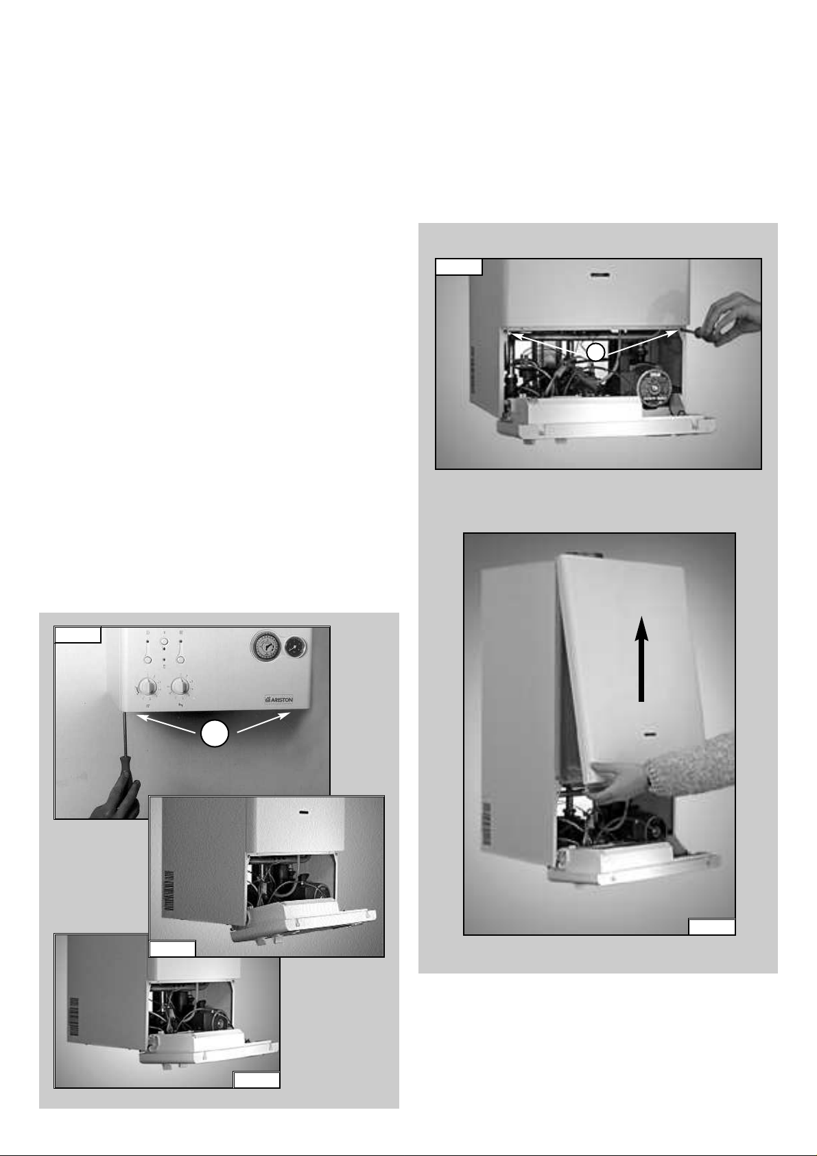
2. The control panel moves downward and when pulled forward,
rotates on two lateral hinges; the panel stays in a semihorizontal position, which allows access to the inner parts of
the boiler (FIG. 1.2);
3. In order to increase the manoeuvring space, it is possible to
raise the control panel and rotate it to a fully horizontal position
(FIG. 1.3);
4. Remove the screws “B” from the front panel bottom lip
(FIG. 1.4);
5. Lift the front panel up and forward from the raised screws at the
the top of the casing (FIG. 1.5).
FIG. 1.4
B
FIG. 1.5
3
1. SERVICING INSTRUCTIONS
The life of individual components varies and they will need
servicing or replacing as and when faults develop.
The fault finding sequence chart in chapter 2 will help to locate
which component is the cause of any malfunction, and instructions
for removal, inspection and replacement of the individual parts are
given in the following pages.
1.1 REPLACEMENT OF PARTS
1.2 TO GAIN GENERAL ACCESS
All testing and maintenance operations on the boiler require the
control panel to be lowered. This will also require the removal of
the casing.
1.2.1 Removing the front panel
1. Loosen the fastening screws “A”of the control panel located on
the lower part of the panel itself. (FIG.1.1);
A
FIG. 1.3
FIG. 1.1
FIG. 1.2
To ensure efficient safe operation, it is recommended that the
boiler is serviced annually by a competent person.
Before starting any servicing work, ensure both the gas and
electrical supplies to the boiler are isolated and the boiler is
cool.
Before and after servicing, a combustion analysis should be made
via the flue sampling point (please refer to the Installation Manual
for further details).
After servicing, preliminary electrical system checks must be
carried out to ensure electrical safety (i.e.polarity, earth continuity,
resistance to earth and shor t circuit).
4
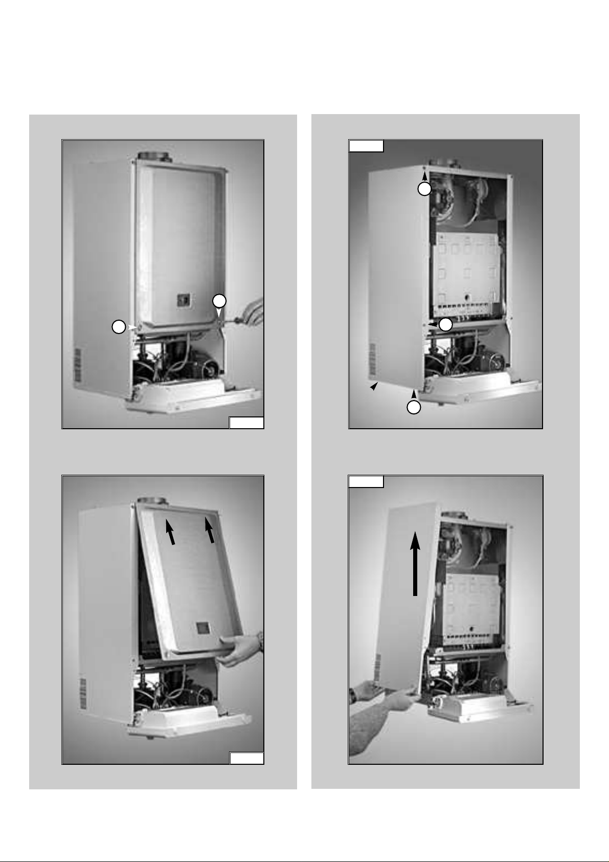
1.2.2 Removing the sealed chamber front cover
1. Remove the screws “C” (FIG. 1.6);
2. Lift the sealed chamber front cover from the locating pins
(FIG. 1.7).
FIG. 1.6
C
C
FIG. 1.7
1.2.3 Removing the side panels
1. Remove the four screws “D” for each side panel (FIG.1.8);
2. Pull the panel away from the boiler at the base, then lift the
panel up and remove from the boiler (FIG.1.9).
D
D
D
FIG. 1.8
FIG. 1.9
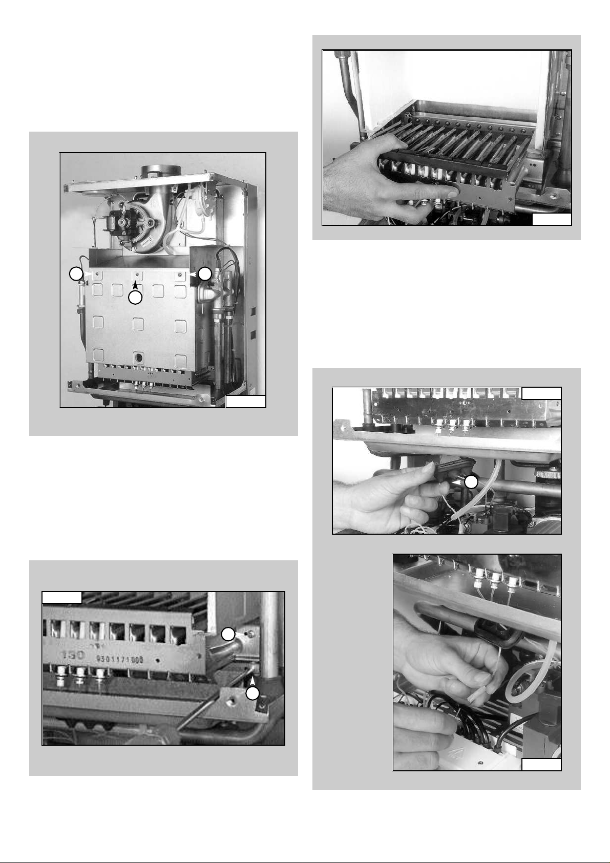
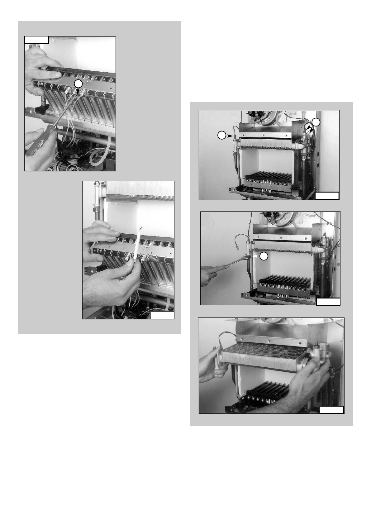
1.3.3 Removing the electrodes
Before carrying out this procedure, unscrew and slide the
burner forward (see previous section).
1. Remove rubber gasket “G” (FIG.1.13);
2. To remove the detection electrode disconnect the cable
at its connection point close to the P.C.B. (FIG. 1.14);
3. Remove screw “H” (FIG. 1.15);
4. Gently slide the electrode downward (FIG. 1.16).
FIG. 1.13
G
FIG. 1.14
1.3.2 Removing the burner and jets
1. Remove the screws “F” from the burner (FIG. 1.11);
2. Remove the burner (FIG. 1.12);
3. Disconnect the electrodes (see section 1.3.3);
4. Remove the jets using a No. 7 socket spanner;
5. Replace in reverse order.
5
1.3.1 Removing the combustion cover
1. Remove the screws “E”(FIG.1.10);
2. Lift off the combustion cover.
1.3 ACCESS TO THE COMBUSTION CHAMBER
E
E
E
FIG. 1.10
FIG. 1.11
Fig. 1.12
F
F
6
To replace, repeat the steps in reverse order, paying
particular attention to the following:
a - Centre the electrode in the positioning hole carefully,
otherwise the electrode may break;
b -Ensure that the left hand and right hand electrodes are
located the correct way round (facing each other), to
give the correct spark gap;
c -Check that the cables have been connected correctly;
d -Check that the rubber gasket covers the cable/ electrode
connection point completely.
FIG. 1.15
FIG. 1.16
H
1. Drain the boiler of water;
2. Remove the overheat thermostat sensor, D.H.W.sensor
and heating sensor “I” (FIG. 1.17);
3. Release the four connection nuts “J”connecting the
exchanger to the flow and return pipes (FIG. 1.18);
4. Pull it straight out (FIG. 1.19).
1.3.4 Removing the main heat exchanger
FIG. 1.18
J
Fig. 1.17
I
FIG. 1.19
I
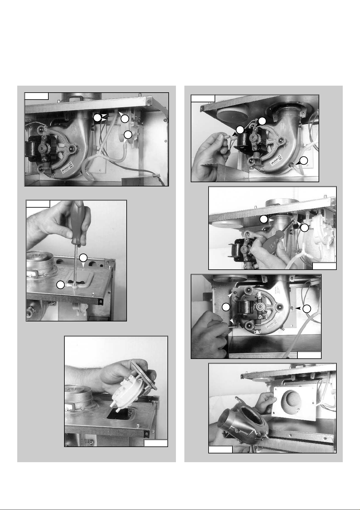
1. Disconnect electrical connections “N” and silicone pipe “O”
(FIG.1.23);
2. Remove screw “P” and remove the fan collar clamp “Q”
(FIG.1.24);
3. Remove screws “R”(FIG.1.25);
4. Remove fan and mounting plate (FIG.1.26).
1.3.6 Removing the fan
1. Disconnect the electrical connections “K” and silicone
pipes “L” from their connection points (FIG. 1.20);
2. Remove screws “M” on the top of the sealed chamber
(FIG. 1.21);
3. Lift out the air pressure switch (FIG. 1.22);
4. Unscrew to remove the switch from the plate.
7
1.3.5 Removing the air pressure switch
FIG. 1.25
R
R
FIG. 1.24
P
Q
FIG. 1.23
N
N
O
FIG. 1.26
FIG. 1.21
FIG. 1.20
L
L
K
M
M
FIG. 1.22
8
1.4 SERVICING AND REMOVAL
OF THE GAS VALVE
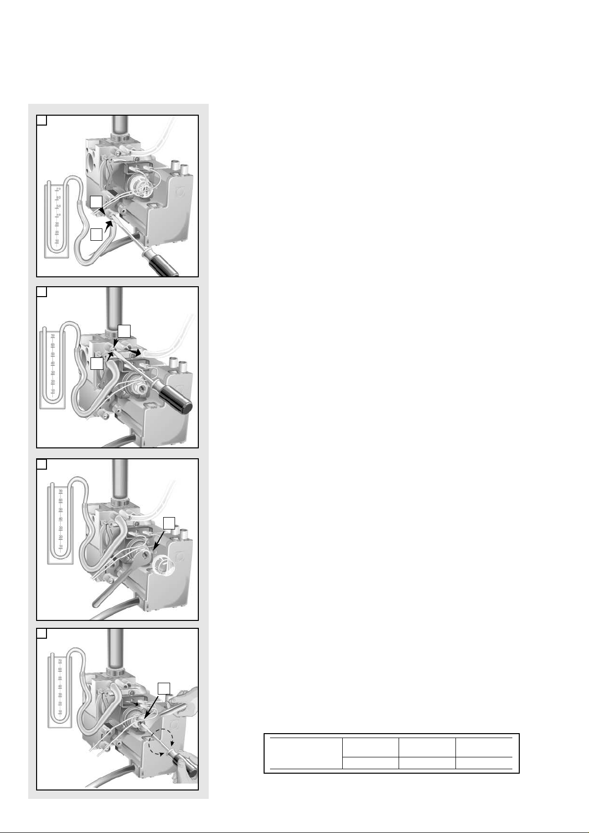
1.4.1 Setting the gas pressures
1
2
3
4
A
B
C
E
F
D
Setting the minimum and the maximum power of the boiler
1. Check that the supply pressure to the gas valve is a minimum of 20 mbar
for natural gas.
2. To do this, loosen the screw “A”.
Fit the pipe of the pressure gauge to the inlet pressure connection of the
gas valve “B”.
When you have completed this operation, replace the screw “A” securely
into its housing to seal off the gas.
3. To check the pressure supplied by the gas valve to the bur ner, loosen the
screw “C”. Fit the pipe of the pressure gauge to the pressure outlet test
point of the gas valve “D”.
Disconnect the compensation pipe either from the gas valve or from the
sealed chamber.
4. Push the On/Off button to “ON”position -green light- and push the Heating
button to “ON” position -green light-
Turn on the boiler by running a hot water tap.
Adjust the 10mm nut “E” on the modureg to set the maximum gas
pressure, turn the nut clockwise to increase and anti clockwise to decrease
the pressure until the required pressure is achieved (see T
ABLE A page 9)
5. To set the minimum power , disconnect a supply terminal from the modureg
and adjust screw “F”.
Turn the screw clockwise to increase the pressure and counter-clockwise to decrease the pressure (displayed on the
pressure gauge) corresponding to the minimum power (see TABLE A page
9).
6. When you have completed the above operations, turn off the
hot water tap, re-connect the supply terminal to the modureg
on the gas valve and replace the cap on the screw of the
modureg.
Setting the maximum heating circuit power
7. To set the maximum heating circuit power, push the On/Off button to the
“ON” position -green light- and push the Heating button and set the time
clock and any external controls to the “ON” position -green light.Turn the
knob of the heating thermostat clockwise to maximum.
8. Remove the inspection panel of the P.C.B. and fit a small cross-head
screwdriver in to the right hand potentiometer.Tur n clockwise to increase
the pressure or counter-clockwise to reduce the pressure. Adjust the
setting to the required heating pressure value (displayed on the pressure
gauge), as indicated in the charts shown in page 9.
9. Turn off the boiler by placing the main switch to the "OFF" position.
Setting pressure for soft ignition.
Disconnect the detection electrode connection close to the P.C.B. (F
IG.
1.14).
Start the boiler and during the ignition sequence adjust the left hand
potentiometer until the gas pressure reads the required gas pressure as
per the table below.
Once the gas pressure is set turn off the boiler and re-connect the
connection to the P.C.B.
NATURAL GAS (G20) BUTANE GAS (G30) PROPANE GAS (G31)
Recommended pressure for
soft-light ignition
8 mbar
16 mbar
16 mbar
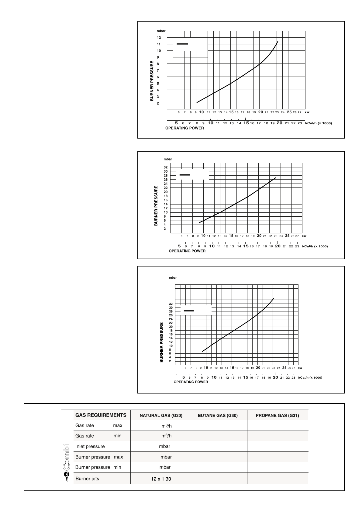
9
Regulating the heating power for
natural gas (G20)
Regulating the heating power for
butane gas (G30)
Regulating the heating power for
propane gas (G31)
TABLE A
CG010A
CG011A
CG012A
model 23
model 23
23 MFFI
2.78
1.16
20
40
38
36
34
model 23
2.02 Kg/h
0.87 Kg/h
28 mbar
2.00 Kg/h
0.85 Kg/h
37 mbar
11.0
2.0
27.5 mbar
6.2 mbar
12 x 0.77
35.5 mbar
7.3 mbar
12 x 0.77

10
1.4.2 Removing the spark generator
1. Disconnect ignition leads “S” by pulling upward
(FIG. 1.27);
2. Remove the screw “T” (FIG.1.28);
3. Remove the spark generator by pulling forward from the
gas valve (FIG.1.29).
NB.: It may be necessary to reset the flame failure reset
a number of times during this operation.
10. Remove the pipe from the pressure gauge and connect
screw “C” to the pressure test point in order to seal off
the gas.
11.Carefully check the pressure test points for gas leaks
(valve inlet and outlet).
IMPORTANT!
Whenever you disassemble and reassemble the gas
connections, always chec k f or leaks using a soap and water
solution.
FIG. 1.27
FIG. 1.28
FIG. 1.29
S
T
Soft-light
Adjustment
Max Heating
Adjustment

11
Important! Before any component is removed, the boiler
must be drained of all water.
1.5.1 Removing the pump pressure switch
1.Remove the pump pressure switch electrical connections
“W”(FIG1.33);
2.Unscrew the pump pressure switch by
using
a spanner on
the nut;
3.Remove the pump pressure switch.
1.5 ACCESS TO THE WATER CIRCUIT
FIG. 1.30
FIG. 1.31
FIG. 1.32
FIG. 1.33
U
V
V
1.4.3 Removing the gas valve
Important! Before removing the gas valve, ensure the gas
supply is turned off.
1. Disconnect all the cables from the solenoid and
modureg;
2. Remove the spark generator (see previous section);
3. Release the nuts “U” (FIG. 1.30);
4. Remove the screws “V”from the bottom of the gas valve
(FIG. 1.31);
5. Remove the gas valve (FIG.1.32).
W
U

12
1.5.3 Removing the automatic air vent
1. Unscrew valve top “Y” (FIG. 1.35);
2. Remove valve complete with float (FIG 1.36).
FIG. 1.35
Y
FIG. 1.36
1.5.2 Removing the safety valve
1. Disconnect the discharge pipe work from below the
boiler;
2. Unscrew and remove the valve “X” (FIG. 1.34).
FIG. 1.34
X

13
1.5.4 Removing the pump
1. Remove the U-clip “ Z”(FIG. 1.37);
2. Remove the retaining clips “A1” (FIG. 1.38);
3. Release the nut “C1” (FIG. 1.39);
4. Remove the pipe “D1” (FIG. 1.40);
5. Remove the screws “E1”(FIG.1.41);
6. Remove the pump.
Z
FIG. 1.37
FIG. 1.38
FIG. 1.39
A1
C1
Z
FIG. 1.40
FIG. 1.41
D1
E1
E1

14
1.5.6 Removing the expansion vessel
1. Release nuts “G1” and remove the gas pipe (FIG. 1.44);
2. Release nut “H1” (FIG. 1.45);
3. Remove back-nut “I1”(FIG.1.46);
4. Remove the expansion vessel (FIG. 1.47).
1.5.5 Removing the pressure gauge
1. Remove the U-clip “F1” (FIG. 1.42)
2. Remove the pressure gauge coupling (FIG. 1.42);
3. Push the pressure gauge through the control panel from
the rear (FIG. 1.43).
FIG. 1.44
F1
FIG. 1.43
G1
H1
FIG. 1.45
FIG. 1.46
FIG. 1.47
G1
I1
FIG. 1.42

15
1.5.7 Removing the overheat thermostat
1. Disconnect the overheat thermostat electrical
connections “J1” (FIG. 1.48);
2. Then remove the thermostat from its mounting by
releasing the securing clip (FIG. 1.49 /1.50).
1.5.8 Removing the heating temperature sensor
(N.T.C.)
1. Pull off the electrical connector and unscrew the sensor
probe using a suitable spanner (FIG. 1.51).
FIG. 1.48
FIG. 1.49
1.5.9 Removing the D.H.W. temperature sensor (N.T.C.)
1. Pull off the electrical connector and unscrew the sensor
probe using a suitable spanner (FIG. 1.52).
J1
FIG. 1.51
FIG. 1.50
FIG. 1.52

16
1.6 ACCESS TO THE CONTROL SYSTEM
FIG. 1.53
1.6.1 Checking the fuses
1. Remove the inspection cover on the reverse of the
control panel (FIG. 1.54);
2. Remove the fuses (FIG.1.55).
FIG. 1.54
FIG. 1.55
M1
N1
Important! Isolate the electr ical supply to the boiler before
accessing the control panel.
1.5.10 Removing the D.H.W. flow switch
1. Unplug the electrical connector “M1” (FIG. 1.59);
2. Release the retaining clip “N1” and remove the D.H.W.
flow switch.

17
1.6.3 Removing the P.C.B.
1. Isolate electricity;
2. Remove the inspection cover from the reverse of the
control panel;
3. Unplug all electrical connections from the P.C.B.
4. Remove the screws “R1” (FIG.1.59);
5. Separate the facia panel from the rear of the control
panel ;
7. Remove the screws “S1” and remove the P.C.B.
(FIG. 1.60).
FIG. 1.59
R1
R1
R1
FIG. 1.60
S1
S1
1.6.2 Removing the time clock
1. Disconnect the electrical connections “P1” from the
clock (FIG. 1.56);
2. Remove screws “Q1” (FIG.1.57);
3. Lift out the time clock from the control panel (FIG. 1.58).
FIG. 1.56
FIG. 1.57
FIG. 1.58
P1
Q1
Q1

18
2. FAULT FINDING
It is possible to detect and correct any defect by using the standard fault
finding diagrams described in this chapter.
2.1 FAULT FINDING GUIDE
(FLOW-CHARTS)

19
IS THE PUMP
RUNNING?
NO
NO
YES
YES
POWER T O
THE PUMP?
1 - Check that the pump
is not stuck
2 - Release/replace pump
1 - Check system pressure
2 - Check pump cable.
3 - Check/replace P.C.B

20
IS THE FAN
RUNNING?
BOILER
SHUTDOWN?
POWER
TO FAN?
NO
YES
YES
NO
YES
NO
NO
YES
1 - Check/replace air
pressure switch
2 - Check if reset button
is jammed
3 - Check/replace flame
detection electrode
1 - Check/replace
connection cable
2 - Check/replace P.C.B.
3 - Check air pressure
switch is not stuck
the N.O. position
1 - Replace fan
1 - Reset the boiler
INTERNAL
P.C.B. PROTECTIONS
ACTIVATED?

21
IS THE BURNER
ALIGHT?
POWER TO
GAS VALVE?
POWER
TO SPARK
GENERATOR?
YES YES
NO
YES
YES
NO
NO
NO
NO
YES
1 - Check/replace cable
2 - Check/replace P.C.B.
1 - Check/replace cable
2 - Check/replace P.C.B.
1 - Check if flame strikes
detection electrode
2 - Check soft-light gas
pressure
3 - Check/replace detection
electrode
4 - Check/replace P.C.B.
1 - Check/replace spark
generator
2 - Check/replace ignition
electrodes and cables
3 - Check spark gap
1 - Check gas supply pressures
2 - Check gas pressure to
burner
3 - Check spark gap
4 - Check/replace gas valve
IS THE
AIR PRESSURE SWITCH
ACTIVATED?
CHECK
∆P ON AIR
PRESSURE TEST
POINT
HAS THE
BOILER SAFETY
SHUTDOWN BEEN
ACTIVATED?
1 - Check exhaust/air intake
2 - Check venturi & tubes
3 - Check fan efficiency/replace
1 - Check/replace A.P. switch
P ≥0.55mbar
P 0.55mbar
∆
∆
≤
YES
DOES
THE SPARK
SEQUENCE
START?
NO

22

23
3. ELECTRICAL
DIAGRAMS
LEGEND:
A = Central Heating Temperature Adjustment
B = Domestic Hot Water Temperature Adjustment
C = Soft-light Adjustment
D = Maximum Heating Adjustment
E = Time Clock Connector
F = On/Off Switch
G = Fume Sensor L.E.D.
H = Central Heating Selector
I = Ignition Failure (Lockout) L.E.D.
J = On/Off L.E.D.
K = Reset Button
L = Central Heating L.E.D.
M = Transformer
N = Circulation Pump Relay
O = Fan Relay
P = Gas Valve Relay
Q = Spark Generator I.C.
A01 = Circulation Pump
A02 = Fan
A03 = Spark Generator/Gas Valve Supply
A04 = Flame Detection Circuit
A05 = Detection Electrode
A06 = Main Circuit Temperature Probe
A07 = Domestic Hot Water Temperature Probe
A08 = D.H.W. Flow Switch
A09 = Pump Pressure Switch
A10 = Modulator
A11 = Air Pressure Switch
A12 = Safety Thermostat
A13 = Exter nal (Room) Thermostats
Colours:
Gry = Grey
Wh = White
Pnk = Pink
Brn = Brown
Bl = Blue
Blk = Black
Rd/Blk = Red/Black

24
microCombi 23 MFFI
SE016A
SF013A

25
4. SHORT SPARE
PARTS LIST
microCombi 23 MFFI

26

27
NOTES

23 99 841590 000 Stampa: Bieffe Recanati
Manufacturer: Merloni TermoSanitari SpA - Italy
Commercial subsidiary: MTS (GB) LIMITED
MTS Building
Hughenden Avenue
High Wycombe
Bucks HP13 5FT
Telephone: (01494) 755600
Fax:(01494) 459775
Internet: http://www.mtsgb.ltd.uk
E-mail: info@mtsgb.ltd.uk
Technical Service Hot Line: (01494) 539579
 Loading...