

Aristocrat MK4-5 Service Manual 1


NEW SOUTH WALES
NEW SOUTH WALES
NEW SOUTH WALESNEW SOUTH WALES
MK4/5XR
MK4/5XR
MK4/5XRMK4/5XR
VIDEO GAMING MACHINE
VIDEO GAMING MACHINE
VIDEO GAMING MACHINEVIDEO GAMING MACHINE
TM
SERVICE MANUAL
AM-1121032-01
JUBILEE GAMING TECHNOLOGY,
A DIVISION OF ARISTOCRAT LEISURE INDUSTRIES PTY LTD (ACN 001 660 715)
71 Longueville Road, Lane Cove NSW 2066, Australia. Telephone: (612) 9413 6300
PO Box 808, Lane Cove NSW 1595, Australia. Fax: (612) 9420 1326

© Aristocrat Leisure Industries Pty Ltd 2000
The gaming machine described in this document may be covered by patents and registered designs. This
document is protected by copyright. No part of it may be reproduced or copied without the written
permission of Aristocrat Leisure Industries Pty Ltd, Australia. This document is not for use in countries
where gaming machines are prohibited by law.
Aristocrat Leisure Industries Pty Ltd reserves the right to change, without notice, the design or
specification of the gaming machine covered by this document. Additional information is available from
time to time in the form of technical bulletins. New editions of this document may change its contents.
WARNING
This is a Class A product. In a domestic
environment, this product may cause radio
interference, in which case the user may be
required to take adequate action.
CAUTION
All functions of the machine are controlled by
complex electronics. Unqualified personnel
must not interfere with any mechanisms or
controls as this may permanently damage
the machine and lead to expensive repairs
or component replacement, and will render
the warranty void.
IImmppoorrttaanntt SSaaffeettyy IInnffoorrmmaattiioon
n
This document contains important information about the use of the equipment and hazards
involved in owning and operating the equipment to which it relates. The equipment can be very
hazardous if used other than in accordance with this document.
Inform Yourself and Your Staff
You must read this document before using the equipment or opening any part of the equipment. Ensure your
staff do too.
The equipment itself is marked with important warning labels detailing dangers.
♦ Check for warning labels whenever opening any part of the equipment.
♦ Read and comply with all warning labels you see when operating or opening the equipment.
♦ Under no circumstances remove or alter any warning label.
Be Careful
If you don’t follow the directions in this manual and on warning labels you increase the risk of the
following things occurring:
♦ serious personal injury, including electrocution and amputation. Unless you are a trained technician, tampering
with the machine can kill you.
♦ serious damage to the equipment;
♦ serious damage to other equipment;
♦ serious damage to the premises housing the equipment;
II Introduction

NSW MK4/5XR Video Service Manual Record of Amendments
Record of Amendments
Amendment
Number
Amendment Date Insertion Date Your Initials
Introduction
III

Record of Amendments NSW MK4/5XR Video Service Manual
Amendment
Number
Amendment Date Insertion Date Your Initials
IV
Introduction

NSW MK4/5XR Video Service Manual Table of Contents
Aristocrat Jubilee MK4/5XR Manuals
Operator Manual
Primarily intended for operators of Aristocrat
Mk4/5XR Video Gaming Machines. The Operator
Manual:
• gives a general overview of the hardware and
software
• provides procedures for daily operations and
simple maintenance.
Service Manual
Primarily intended for service technicians. The
Service Manual:
• gives a general overview of the hardware and
software
• provides instructions for installation and fault
finding
• describes in detail each of the major
components of the machine.
Parts Catalogue
Primarily intended for operators and service
technicians. It enables operators and service
technicians to order machine parts. The Parts
Catalogue:
• shows an illustration of each of the
components of the machine
Introduction
• links each illustration with a part number.
V

Table of Contents NSW MK4/5XR Video Service Manual
This page intentionally left blank
VI
Introduction

NSW MK4/5XR Video Service Manual Table of Contents
Foreword
How To Use This Manual
Purpose of the Manual
This manual provides procedures for the servicing and maintenance of
Aristocrat’s Jubilee Mk4/5XR Series Video Gaming Machine. It covers areas of
machine operation that must be carried out by licensed technicians.
User of the Manual
The manual is aimed at technicians who need to understand detailed and
technically complex aspects of the machine to service and maintain it.
Warnings, Cautions and Notes
WARNING
Units of Measure
A warning immediately precedes an
operating procedure or maintenance practice
which, if not correctly followed, could result
in personal injury or loss of life.
CAUTION
A caution immediately precedes an
operating procedure or maintenance practice
which, if not strictly observed, could result in
damage to or destruction of the equipment,
or corruption of the data.
Note
A note immediately precedes or follows an
operating procedure, maintenance practice
or condition which requires highlighting.
The manual uses the international system of units. The following conversion is
provided for the convenience of readers.
Introduction
1 W = 3.41241 Btu/hour 1 Btu/hour = 0.2930711 W
1 kJ = 0.948 Btu 1 Btu = 1.06 kJ.
VII

Table of Contents NSW MK4/5XR Video Service Manual
Brief History of Aristocrat Leisure Industries
Aristocrat Leisure Industries (ALI), established in 1953, is one of the oldest and most successful gaming machine manufacturers. ALI has supplied
machines to every country and region in the world where gaming machines are legal, including Austria, France, Germany, Holland, Malaysia, New
Zealand, the Philippines, Africa, Singapore, Russia, South America, and the USA.
Aristocrat Leisure Industries employs over 1,400 people and has the largest gaming research and development facility in the Southern Hemisphere.
Offices
Spare Parts Department
PO Box 155, Rosebery, NSW 1445, Australia
Outside Australia Tel: 612 9697 4146 Fax: 612 9697 4199
Within Australia Tel: 02 9697 4146 Fax: 02 9697 4199
Head Office
New South Wales
Aristocrat Leisure Industries Pty Ltd (ACN 001 660 715),
71 Longueville Road, Lane Cove NSW 2066, Australia.
PO Box 808, Lane Cove NSW 1595, Australia.
Outside Australia Tel: 612 9413 6300 Fax 612 9420-1326
Within Australia Tel: 02 9413 6300 Fax 02 9420-1326
Manufacturing / Operations
New South Wales
Aristocrat Leisure Industries Pty Ltd (ACN 001 660 715),
85-113 Dunning Avenue, Rosebery NSW 2018, Australia.
Outside Australia Tel: 612 9697 4000 Fax: 612 9693 1340
Within Australia Tel: 02 9697 4000 Fax: 02 9693 1340
National Offices
South Australia
Aristocrat Leisure Industries Pty Ltd.
75 Henley Beach Road,
Mile End, South Australia 5031.
Outside Australia Tel: 6108 8443 3664 Fax: 618 8443 3606
Within Australia Tel: 08 8443 3664 Fax 08 8443 3606
Victoria
Aristocrat Leisure Industries Pty Ltd.
672 Lorimer Street, Port Melbourne, Victoria. 3207
Outside Australia Tel: 613 9644 1000 Fax: 613 9644 1032
Within Australia Tel: 03 9644 1000 Fax: 03 9644 1032
Queensland
Aristocrat Leisure Industries Pty. Ltd.
60-62 Commercial Drive, Shailer Park, Qld. 4128, Australia
Outside Australia Tel: 617 3801 4444 Fax 617 3801 4403
Within Australia Tel: 07 3801 4444 Fax 07 3801 4403
Western Australia
Aristocrat Leisure Industries Pty. Ltd.
PO Box 8206, Perth Business Centre, Perth WA 6846
Outside Australia Tel: 618 9355 1212 Fax: 618 9355 1213
Within Australia Tel: (08) 9355 1212 Fax: (08) 9355 1213
International Offices
New Zealand
Auckland Office
Aristocrat Leisure Industries (NZ) Ltd,
22 Vestey Drive, Mt. Wellington, Auckland, New Zealand.
Tel: 0011 64 9 270 1600 Fax: 0015 64 9 270 1601
Christchurch Office
Unit D 5 Tenahaun Place, Sockburn,
Christchurch, New Zealand.
Tel: 0011 64 3 338 7430 Fax: 0015 64 3 338 6492
Russia
Aristocrat (Russia),
GPO Box 134, 122108 Moscow, Russia.
Tel / Fax: 0011 7 095 146 1326
UK
Aristocrat Europe
Falcon Unit 1, Stonefield Way, South Ruislip,
Middlesex HA4 OJS, England.
Tel: 0011 44 181 426 5822 Fax: 0015 44 181 426 5762
USA
Nevada
Aristocrat Incorporated,
9895 Double R. Boulevard, Suite 200,
Reno, Nevada 89511, USA.
Tel: 0011 1 702 850 7767 Fax: 0011 1 702 860 5646
California
Aristocrat Incorporated,
10960 W.River Street. #101E Truckee, CA 96161, USA.
Tel: 0011 1 916 582 9570 Fax: 0015 1 916 582 1305
Latin America
1500 N.W. 79 Avenue, Miami, Florida, 33126 USA
Tel: 0011 1 305 594 2881 Fax: 0015 1 305 594 9022
South Africa
ALI Gaming Solutions (Pty.) Ltd.,
PO Box 2570, Bramley 2018, South Africa.
Tel: 0011 27 11 448 2320/1 Fax: 0015 27 11 448 2322
Japan
Tel: 0011 813 576 00071 Fax: 0015 813 576 00072
VIII
Introduction

Table of Contents NSW MK4/5XR Video Service Manual
Table of Contents
General Description 1-1
1.1 Physical Description.......................................................................1-3
1.2 Basic Operation .............................................................................. 1-8
1.2.1 Play Mode......................................................................................... 1-8
1.2.2 Operator Mode................................................................................ 1-10
Installation 2-1
2.1 Pre-Installation Requirements.......................................................2-3
2.2 Inspection on Delivery....................................................................2-5
2.3 Installation Procedure .................................................................... 2-5
2.3.1 Mounting........................................................................................... 2-5
2.3.2 Pre-start Connections, Checks and Power Up .................................2-7
2.3.3 Commissioning the Machine............................................................. 2-8
Machine Modes 3-1
3.1 Modes of Operation ........................................................................ 3-3
3.2 Play Mode ........................................................................................ 3-4
3.2.1 Player Operation............................................................................... 3-5
3.2.2 Video Display.................................................................................... 3-7
3.2.3 Sounds and Tunes............................................................................ 3-8
3.2.4 Pushbuttons...................................................................................... 3-8
3.2.5 Machine Self-Monitoring ................................................................... 3-8
3.2.7 Electromechanical Meters ..............................................................3-11
3.2.9 Audit Meters (Soft Meters).............................................................. 3-13
3.3 Operator Mode .............................................................................. 3-14
3.3.1 Machine Identification.....................................................................3-16
x
Revision 01

NSW MK4/5XR Video Service Manual Table of Contents
3.3.2 Accounting Information................................................................... 3-16
3.3.3 Diagnostic Information Menu.......................................................... 3-21
3.3.4 Self Test Mode ............................................................................... 3-24
3.3.5 Operator Setup / Selections Mode ................................................. 3-30
3.3.6 Power Save Mode .......................................................................... 3-33
3.3.7 Current Lockup Menu – Fault Mode ............................................... 3-33
Cabinet, Door and Top Box 4-1
4.1 General Description ....................................................................... 4-3
4.2 Technical Description .................................................................... 4-5
4.2.1 Cabinet Door .................................................................................... 4-5
4.2.2 Latch Bar .......................................................................................... 4-5
4.2.3 Keyed Lock....................................................................................... 4-7
4.2.4 Cabinet Security ............................................................................... 4-7
4.2.5 Key Switches .................................................................................... 4-9
4.2.6 Bilock Locks.................................................................................... 4-10
4.2.7 Cash Box and Chute ...................................................................... 4-11
4.2.8 Logic Cage ..................................................................................... 4-11
4.2.9 Game Display Shelf........................................................................ 4-12
4.2.10 Cabinet Door Fluorescent Lighting ................................................. 4-12
4.2.11 Cabinet Door Artwork ..................................................................... 4-13
4.2.12 Mid Trim Panel ............................................................................... 4-14
4.2.13 Playbuttons..................................................................................... 4-14
4.2.14 Top Trim Panel ............................................................................... 4-17
4.2.15 Monitor Mask .................................................................................. 4-18
4.2.16 Coin Tray ........................................................................................ 4-19
4.2.17 Belly Panel Door............................................................................. 4-19
4.2.18 Belly Panel Security........................................................................ 4-20
4.2.19 Top Box .......................................................................................... 4-20
4.2.20 Top Box Artwork ............................................................................. 4-20
4.2.21 Top Box Fluorescent Lighting ......................................................... 4-20
4.3 General Maintenance ................................................................... 4-23
Revision 01
xi

Table of Contents NSW MK4/5XR Video Service Manual
Power Supply Assembly 5-1
5.1 Physical Description.......................................................................5-3
5.2 Basic Operation .............................................................................. 5-5
5.3 Functional Specification ................................................................5-7
5.3.1 Input Requirements ..........................................................................5-7
5.3.2 Output Requirements........................................................................ 5-7
5.3.3 Control Signals .................................................................................5-9
5.3.4 Physical Connections .......................................................................5-9
5.4 Removal and Replacement Procedures .....................................5-11
5.4.1 Fuses..............................................................................................5-11
5.4.2 Power Supply Assembly ................................................................. 5-11
5.5 General Maintenance.................................................................... 5-12
Coin Handling Assembly 6-1
6.1 Overview.......................................................................................... 6-3
6.2 Basic Operation .............................................................................. 6-4
6.2.1 Validation .......................................................................................... 6-4
6.2.2 Rejected Coins .................................................................................6-5
6.2.3 Accepted Coins................................................................................. 6-5
6.2.4 Alarm ................................................................................................6-6
6.2.5 Inhibit All ...........................................................................................6-6
6.2.6 Self Calibration .................................................................................6-6
6.2.6 Diagnostics ....................................................................................... 6-6
6.2.7 Debris Flap .......................................................................................6-6
6.3 Removal and Replacement ............................................................ 6-7
6.4 Clearing Coin Jams ........................................................................ 6-7
6.5 CN133A Coin Validator Connector Pinouts.................................. 6-8
xii
Revision 01

NSW MK4/5XR Video Service Manual Table of Contents
6.6 Diverter Solenoid and Photo-Optic Sensor.................................. 6-9
6.6.1 Physical Description ......................................................................... 6-9
6.6.2 Basic Operation ................................................................................ 6-9
6.6.3 Removal and Replacement ............................................................ 6-10
6.7 Fault Finding ................................................................................. 6-11
6.8 General Maintenance ................................................................... 6-11
Bank Note Acceptor 7-1
7.1 Technical Description .................................................................... 7-3
7.1.1 Overview........................................................................................... 7-3
7.1.2 Physical Description ......................................................................... 7-3
7.1.3 VFM4 Non-isolated Serial Interface................................................ 7-10
7.2 Installation and Machine Conditions .......................................... 7-13
7.2.1 Configuration Setup........................................................................ 7-13
7.2.2 Machine Condition Indicators ......................................................... 7-13
7.3 Removal and Replacement Procedures ..................................... 7-15
7.3.1 Clearing the Bank Note Stacker ..................................................... 7-15
7.3.2 Bank Note Acceptor Assembly ....................................................... 7-16
7.3.3 Clearing Bank Note Acceptor Jams................................................ 7-16
7.4 Care and Maintenance ................................................................. 7-18
7.4.1 Troubleshooting.............................................................................. 7-18
7.4.2 Periodic Maintenance ..................................................................... 7-20
7.4.3 Video Level Calibration................................................................... 7-20
Hopper 8-1
8.1 Technical Description .................................................................... 8-3
8.1.1 Physical Description ......................................................................... 8-3
8.1.2 Basic Operation ................................................................................ 8-6
8.1.3 Functional Description ...................................................................... 8-7
8.1.4 Hopper Interface Signals.................................................................. 8-7
Revision 01
xiii

Table of Contents NSW MK4/5XR Video Service Manual
8.2 Removal and Replacement ............................................................ 8-8
8.2.1 Removal............................................................................................ 8-8
8.2.2 Replacement..................................................................................... 8-8
8.3 Clearing Coin Jams ........................................................................ 8-9
8.4 Disassembly and Assembly......................................................... 8-10
8.4.1 Disassembly ...................................................................................8-10
8.4.2 Assembly ........................................................................................8-11
8.5 Fault Finding ................................................................................. 8-12
8.6 General Maintenance.................................................................... 8-13
Video Monitor 9-1
9.1 Ceronix Monitor - General Description ......................................... 9-3
9.2 Technical Description ....................................................................9-4
9.2.1 Power Supply.................................................................................... 9-4
9.2.2 Adjustment Procedures ....................................................................9-4
9.3 Removal and Replacement ............................................................ 9-6
9.4 General Maintenance...................................................................... 9-6
9.5 Degaussing .....................................................................................9-7
Electromechanical Meters 10-1
10.1 General Description...................................................................... 10-3
10.2 Functional Description ................................................................. 10-4
10.2.1 Serial Interface................................................................................ 10-4
10.2.2 Overcurrent Protection.................................................................... 10-5
10.2.3 Meter Drive Outputs........................................................................ 10-5
10.2.4 PCB Expansion............................................................................... 10-5
10.2.5 Light Tower Interface ...................................................................... 10-5
10.2.6 Security Interface............................................................................ 10-5
xiv
Revision 01

NSW MK4/5XR Video Service Manual Table of Contents
10.2.7 Meter Detection .............................................................................. 10-5
10.3 Removal and Replacement Procedures ..................................... 10-7
10.4 Connector Pin Assignment.......................................................... 10-8
10.5 General Maintenance ................................................................. 10-10
Main Board 11-1
11.1 Introduction................................................................................... 11-4
11.2 Physical Description .................................................................... 11-5
11.2.1 Diagrams and Component Locations ............................................. 11-5
11.3 Functional Description................................................................ 11-6
11.3.1 Main Board Functions..................................................................... 11-7
11.4 Technical Description ................................................................. 11-8
11.4.1 ARM250 Microprocessor .............................................................. 11-10
11.4.2 Sound ........................................................................................... 11-11
11.4.3 Video ............................................................................................ 11-12
11.4.4 Reset ............................................................................................ 11-12
11.4.5 Debug (Keyboard) Port................................................................. 11-13
11.4.6 Debugging .................................................................................... 11-13
11.4.7 External I/O Expansion................................................................. 11-14
11.4.8 Mikohn Link Progressive Interface (where fitted).......................... 11-14
11.4.9 Memory......................................................................................... 11-15
11.4.10 Real Time Clock .......................................................................... 11-16
11.4.11 Battery Backup Circuit................................................................. 11-16
11.4.12 Power Control Interface............................................................... 11-17
11.4.13 SPI Bus Driver and Multiplexer Circuitry...................................... 11-18
11.4.14 Printer and Mechanical Meters.................................................... 11-19
11.4.15 Mechanical Switches................................................................... 11-19
11.4.16 Security ....................................................................................... 11-19
11.4.17 Coin Handling System................................................................. 11-20
11.4.18 Hopper Interface ......................................................................... 11-21
Revision 01
xv

Table of Contents NSW MK4/5XR Video Service Manual
11.4.19 Serial Channels ........................................................................... 11-21
11.4.20 Bank Note Acceptor..................................................................... 11-22
11.4.21 Interface Board ............................................................................ 11-22
11.5 Removal and Replacement Procedures ..................................11-23
11.6 Description of Connectors......................................................... 11-24
11.6.1 Communications Configuration Board .......................................... 11-24
11.6.2 Optically Isolated Connector - P20 ............................................... 11-26
11.6.3 Miscellaneous Connector - P22....................................................11-28
11.6.4 Security and I/O Expansion Connector - P21 ............................... 11-30
Interface Board Part No. 410315 Issue B 12-1
12.1 Physical Description.....................................................................12-3
12.1.1 Diagrams and Component Locations .............................................12-3
12.2 Technical Description ..................................................................12-5
12.3 Description of Connectors........................................................... 12-7
12.3.1 Main Board Connectors - P1, P2, and P3....................................... 12-7
12.3.2 Driver Board, P4 ............................................................................. 12-7
12.3.3 LAB Comms, P5 ............................................................................. 12-7
12.3.4 Mechanical Meters, P6 ...................................................................12-7
12.3.5 Security - P8, P22, and P24 ...........................................................12-7
12.3.6 Door Signals Interface - P10 and P11 ............................................ 12-9
12.3.7 Coin Handling, P12 ....................................................................... 12-10
12.3.8 Bill Acceptor, Backlight and Security, P13 .................................... 12-11
12.3.9 Serial Channels - P14, P15, P17, and P18................................... 12-11
12.3.10 DACOM 5000, P21...................................................................... 12-13
12.3.11 Mikohn, P16................................................................................. 12-13
12.3.12 SPI Channel 1, P19 ..................................................................... 12-14
12.3.13 DACOM 3000, P20...................................................................... 12-14
12.3.14 Spare Voltage 24 V DC, P23....................................................... 12-15
12.3.15 Hopper, P25 ................................................................................12-15
12.3.16 Video, P26 ................................................................................... 12-15
xvi
Revision 01

NSW MK4/5XR Video Service Manual Table of Contents
12.3.17 Mechanical Switches - P27 ......................................................... 12-16
12.3.18 Audit / Jackpot switch and door security, P28............................. 12-16
12.3.19 Power Supply, P29...................................................................... 12-17
12.3.20 Optional Fan DC 12 V, P30......................................................... 12-17
12.4 Removal and Replacement Procedures ................................... 12-18
I/O Driver Board - 410415 13-1
13.1 Physical Description .................................................................... 13-3
13.1.1 Circuit Diagrams and Component Locations .................................. 13-3
13.2 Functional Description................................................................. 13-3
13.2.1 Power Supply ................................................................................. 13-6
13.2.2 Pushbuttons and Lamps................................................................. 13-6
13.2.3 Coin Handling Interface .................................................................. 13-7
13.3 Removal and Replacement Procedures ................................... 13-10
13.4 Connector Pin Assignment........................................................ 13-11
Communications Configuration Board - 410217 14-1
14.1 Physical Description .................................................................... 14-3
14.2 Functional Description................................................................. 14-4
14.3 Removal and Replacement Procedures ..................................... 14-6
14.4 Connector Pin Assignments........................................................ 14-7
14.5 General Maintenance ................................................................... 14-7
LAB Communications Board - 410174 15-1
15.1 Technical Description .................................................................. 15-3
15.1.1 Physical Description ....................................................................... 15-3
15.1.2 Basic Operation .............................................................................. 15-6
15.1.3 LAB PSU Chassis Description........................................................ 15-7
Revision 01
xvii

Table of Contents NSW MK4/5XR Video Service Manual
15.2 Removal and Replacement ........................................................ 15-10
15.2.1 Removal........................................................................................ 15-10
15.2.2 Replacement................................................................................. 15-10
15.3 Connector Pin Assignments...................................................... 15-11
15.3.1 Interface Board Slot P6................................................................. 15-11
15.4 General Maintenance.................................................................. 15-13
Progressive Jackpot System 16-1
16.1 Overview........................................................................................ 16-3
16.2. Progressive SEI Board (410227).................................................. 16-3
Machine Fault Finding 17-1
17.1 Fault Finding ................................................................................. 17-3
Games A-1
Spinning Reel Games ................................................................................... A-3
Glossary
Index
xviii
Revision 01

NSW MK4/5XR Video Service Manual Table of Contents
List of Figures
Figure 1-1 Mk4/5XR Series Video Gaming Machine - External View ............................. 1-5
Figure 1-2 Bilock "U" Shaped Keyway and Quick Change Core Features...................... 1-7
Figure 1-3 Basic Game Operation in Play Mode ............................................................. 1-9
Figure 2-1 Machine Dimensions...................................................................................... 2-4
Figure 2-2 Machine Footprint and Clearances ................................................................ 2-6
Figure 3-1 Format of Game Display................................................................................ 3-4
Figure 3-2 Centre Line and Multi Line Combinations ......................................................3-7
Figure 3-3 Typical Pushbutton Layout............................................................................. 3-8
Figure 3-4 Electromechanical Meters............................................................................ 3-12
Figure 3-5 Operator Mode Menu Displays - Structure................................................... 3-15
Figure 4-1 Cabinet and Cabinet Door - General Description .......................................... 4-4
Figure 4-2 Latch Bar........................................................................................................ 4-6
Figure 4-3 Keyed Lock Assembly.................................................................................... 4-7
Figure 4-4 Photo-optic Emitter Adjustment ......................................................................4-8
Figure 4-5 Key Switches: Removal and Replacement ..................................................4-10
Figure 4-6 Bilock "U" Shaped Keyway and Quick Change Core Features.................... 4-10
Figure 4-7 Play Button Lamps ....................................................................................... 4-15
Figure 4-8 Playbutton - Exploded View .........................................................................4-17
Figure 4-9 Top Trim Panel and Monitor Mask.............................................................. 4-18
Figure 4-10 Top Box...................................................................................................... 4-21
Figure 5-1 Power Supply Assembly Location.................................................................. 5-3
Figure 5-2 Power Supply Assembly.................................................................................5-4
Figure 5-3 Power Supply Assembly Wiring Diagram ...................................................... 5-5
Figure 5-4 Low Voltage Power Distribution ..................................................................... 5-6
Figure 6-1 Condor Coin Handling Assembly ................................................................... 6-3
Figure 6-2 Condor Coin Validator.................................................................................... 6-5
Figure 6-3 Diverter Solenoid and Photo-Optic Sensor ....................................................6-9
Figure 7-1 Bank Note Acceptor Assembly ......................................................................7-4
Figure 7-2 Bank Note Acceptor Dual Cage Assembly ....................................................7-5
Figure 7-3 Bank Note Acceptor with open Upper Guide .................................................7-6
Figure 7-4 Stacker ............................................................................................................ 7-7
Figure 7-5 Typical Mid Trim Layout ................................................................................. 7-8
Figure 7-6 Input/Output Connector.................................................................................. 7-9
Figure 7-7 Interconnection Diagram ................................................................................ 7-9
Figure 7-8 Bezel Assembly Indicators - LED Displays .................................................. 7-10
Figure 7-9 VFM4 Protocol - Accept and Return Messages ........................................... 7-11
Figure 7-10 VFM4 Protocol - Hex Code Messages....................................................... 7-12
Figure 7-11 Operator Setup Mode - Machine Options ..................................................7-13
Figure 7-12 Bank Note Acceptor - DIP Switch Location................................................ 7-19
Figure 8-1 Hopper Location (Standard Disc Hopper shown) .......................................... 8-3
Figure 8-2 Hopper- rear view (Standard Disc Hopper Shown)....................................... 8-4
Figure 8-3 Hopper - exploded view (Standard Disc Hopper Shown).............................. 8-5
Figure 8-4 Hopper Photo-optic Detector ....................................................................... 8-13
Figure 9-1 Ceronix Video Monitor and Control Panel...................................................... 9-5
Figure 10-1 Electromechanical Meter Board - Location ................................................ 10-3
Figure 10-2 Electromechanical Meter Board - 410366 Block Diagram .........................10-4
Figure 10-3 Electromechanical Meter Board - 410366 Component and Solder
Sides ............................................................................................................... 10-6
Figure 11-1 Location of Main Board .............................................................................. 11-5
Figure 11-2 System Architecture ................................................................................... 11-6
Figure 11-3 Main Board block diagram .........................................................................11-8
Figure 11-4 Typical Main Board layout (not detailed).................................................... 11-9
Figure 12-1 Interface Board Component Location ........................................................ 12-4
Figure 13-1 I/O Driver Board - Location ........................................................................13-3
Figure 13-2 I/O Driver Board - Block Diagram .............................................................. 13-4
Figure 13-3 I/O Driver Board 410415 - Component Layout........................................... 13-5
Figure 13-4 Coin Handling Interface Signals................................................................. 13-7
Figure 13-5 Timing of Coin Handling Output Signals ....................................................13-8
Revision 01
xix

Table of Contents NSW MK4/5XR Video Service Manual
Figure 14-1 Communications Configuration Board - Location ......................................14-3
Figure 14-2 Communications Configuration Board - Block Diagram ............................ 14-4
Figure 15-1 LAB Communications Board - position in logic cage .................................15-3
Figure 15-2 LAB Communications Board - Component Layout ....................................15-5
Figure 15-3 LAB Communications Board - Block Diagram ........................................... 15-6
Figure 15-4 LAB PSU Chassis ......................................................................................15-8
Figure 15-5 PSU Chassis - PSU Fuse and Connector Wiring ......................................15-8
Figure 15-6 LAB Communications Board and PSU Kit .................................................15-9
Figure 16-1 SEI Board - data flows ...............................................................................16-4
Figure 16-2 Cashcade - data flows................................................................................ 16-6
Figure A-1 MK V Video Game Screen Example...............................................................0-4
Figure A-2 MK V Pay Table Example .............................................................................. 0-5
List of Tables
Table 1-1 Machine Modules ............................................................................................1-3
Table 1-2 Machine Key Types ......................................................................................... 1-6
Table 3-1 Operator Mode Menu ....................................................................................3-14
Table 3-2 Machine Identification Display .......................................................................3-16
Table 3-3 Accounting Information Menu........................................................................3-17
Table 3-4 Accounting Information - Jurisdictional Meters - Screen 1............................3-17
Table 3-5 Accounting Information - Jurisdictional Meters - Screen 2............................3-18
Table 3-6 Accounting Information - Periodic Meters - Screen 1....................................3-18
Table 3-7 Accounting Information - Periodic Meters - Screen 2....................................3-19
Table 3-8 Accounting Information - Reset Periodic Meters ........................................... 3-19
Table 3-9 Accounting Information - Game Replay ........................................................3-19
Table 3-10 Accounting Information – Meters of Last Game.......................................... 3-20
Table 3-11 Accounting Information - Game Statistics ................................................... 3-20
Table 3-12 Accounting Information - Gamble Statistics ................................................3-21
Table 3-13 Diagnostic Information Menu.......................................................................3-21
Table 3-14 Diagnostic Information - Diagnostic Meters - Screen 1 ...............................3-22
Table 3-15 Diagnostic Information - Diagnostic Meters - Screen 2 ...............................3-22
Table 3-16 Diagnostic Information - Error Log ..............................................................3-23
Table 3-17 Diagnostic Information - Panic Log .............................................................3-23
Table 3-18 Diagnostic Information - Bill Acceptor Information ...................................... 3-24
Table 3-19 Self Test Mode Menu ..................................................................................3-24
Table 3-20 Self Test Mode Requirements..................................................................... 3-25
Table 3-21 Self Test Mode - Lamp Test........................................................................ 3-25
Table 3-22 Self Test Mode - Coin Entry Test ................................................................ 3-26
Table 3-23 Self Test Mode - Hopper Test ..................................................................... 3-26
Table 3-24 Self Test Mode - Video Monitor Test Menu.................................................3-27
Table 3-25 Self Test Mode - Video Monitor Test Descriptions ......................................3-27
Table 3-26 Self Test Mode - Sound Effects Test ..........................................................3-28
Table 3-27 Self Test Mode - Factory Test..................................................................... 3-28
Table 3-28 Self Test Mode.- Combination Test............................................................. 3-29
Table 3-29 Self Test Mode - Combination Test Result .................................................3-29
Table 3-30 Operator Setup / Selections Menu ..............................................................3-30
Table 3-31 Operator Setup/Selections - Machine Options Display ...............................3-31
Table 3-32 Operator Setup/Selections - Real Time Clock Setup ..................................3-32
Table 3-33 Operator Setup/Selections - Sound System Setup ..................................... 3-32
Table 3-34 Operator Setup/Selections - Reel Spin Speed Setup................................... 3-32
Table 3-35 Operator Setup/Selections - Layout Setup.................................................. 3-33
Table 3-36 Power Save Mode ....................................................................................... 3-33
Table 3-37 Fault Mode - Current Active Lockup Menu.................................................. 3-34
Table 3-38 Fault Mode - Current Active Lockup Help Screens ..................................... 3-35
Table 6-1 Condor Validator Interface Signals.................................................................. 6-8
Table 6-2 Fault Finding.................................................................................................. 6-11
Table 7-1 Bank Note Acceptor Fault Finding................................................................. 7-18
Table 7-2 Bank Note Acceptor DIP Switch Functions ...................................................7-19
xx
Revision 01

NSW MK4/5XR Video Service Manual Table of Contents
Table 8-1 Fault Finding.................................................................................................. 8-12
Table 10-1 J1 - Main Connector to Interface Board ...................................................... 10-8
Table 10-2 J2 - Meter Drive Output Interface................................................................ 10-8
Table 10-3 J3 - Additional Meters Interface ..................................................................10-9
Table 10-4 J4 - Light Tower Interface ........................................................................... 10-9
Table 10-5 S1 - Security Interface................................................................................. 10-9
Table 11-1 Serial EEPROMs Characteristics.............................................................. 11-16
Table 11-2 Power Control System Signal Lines .......................................................... 11-17
Table 11-3 SPI Channel Signals ................................................................................. 11-18
Table 11-4 Optical Security Sensor Assignment ......................................................... 11-19
Table 11-5 Mechanical Security Switch Assignment................................................... 11-20
Table 11-6 Coin Handling Signals ............................................................................... 11-20
Table 11-7 Hopper Control Signals ............................................................................. 11-21
Table 11-8 Communications Configuration Board connector - P23............................ 11-24
Table 11-9 Optically Isolated Connector - P20............................................................ 11-26
Table 11-10 Miscellaneous Connector - P22 .............................................................. 11-28
Table 11-11 Security and I/O Expansion Connector - P21.......................................... 11-30
Table 12-1 Interface Board Connections....................................................................... 12-6
Table 13-1 Coin Handling Signals - Explanation ........................................................... 13-8
Table 13-2 LED Functions............................................................................................. 13-9
Table 15-1 LAB Port 1 Pinout........................................................................................ 15-4
Table 15-2 LAB Ports 2-6 Pinout................................................................................... 15-4
Table 15-3 Interface Board Bus Connector for LAB Communications Board ............. 15-11
Table 16-1 SEI Board Configurations............................................................................ 16-3
Table 16-2 DIP Switch Settings..................................................................................... 16-5
Table 16-3 Mikohn Interface.......................................................................................... 16-7
Table 16-4 Machine Interface........................................................................................ 16-7
Table 16-5 CDS Display Interface ................................................................................. 16-8
Table 16-6 Mikohn RS-422/485 Serial Interface ........................................................... 16-8
Table 17-1 Fault Finding................................................................................................ 17-3
Revision 01
xxi

NSW MK4/5 Video Service Manual General Description
_____Chapter 1_____
General Description
1.1 Physical Description.............................................................. 1-3
1.2 Basic Operation...................................................................... 1-8
1.2.1 Play Mode ................................................................................ 1-8
1.2.2 Operator Mode ....................................................................... 1-10
Revision 01
1-1

General Description NSW MK4/5 Video Service Manual
List of Figures
Figure 1-1 Mk4/5XR Series Video Gaming Machine - External View.............................. 1-5
Figure 1-2 Bilock "U" Shaped Keyway and Quick Change Core Features...................... 1-7
Figure 1-3 Basic Game Operation in Play Mode ............................................................. 1-9
List of Tables
Table 1-1 Machine Modules ............................................................................................1-3
Table 1-2 Machine Key Types ......................................................................................... 1-6
1-2
Revision 01
NSW MK4/5 Video Service Manual General Description
1.1 Physical Description
Aristocrat’s Jubilee Mk4/5XR series of gaming machines have been developed to
comply with existing and future regulations and to the same technoligcal standard
as the Aristocrat MVP machine.
The machine consists of existing 540 Mk4 cabinets that have been modified to
accept the high standard of the MVP electronics currently being produced by
Aristocrat.
The Mk4/5XR Series gaming machines feature:
• Advanced, high-performance electronics based on ARM RISC technology;
• A wide range of machine options, including note and coin denominations,
communication links, and progressive systems;
• A comprehensive security system;
• Modular design and construction;
• Simplified operation and maintenance procedures;
• High resolution video displays, advanced animation and graphics, and
improved sounds and tunes.
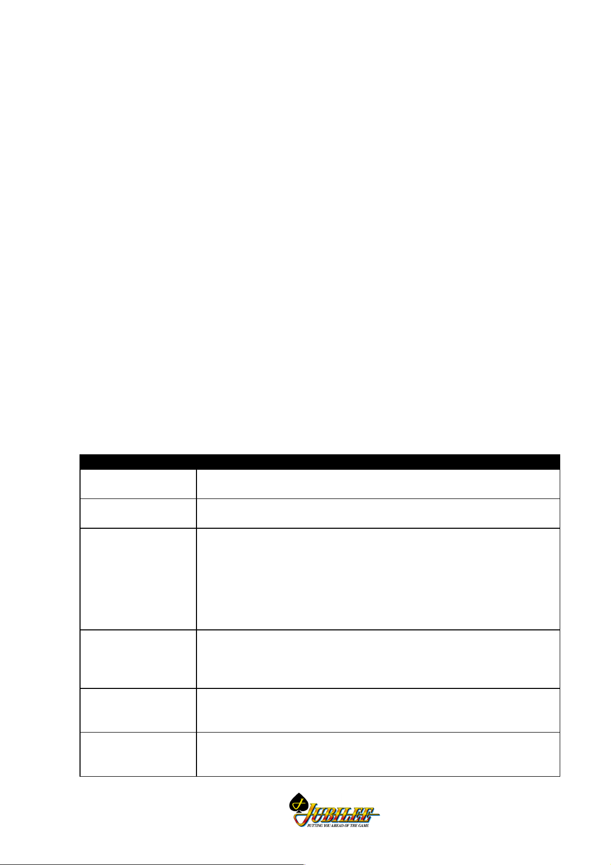
The following table briefly identifies the various modules of the gaming machine.
Figure 1-1 shows the location of machine modules.
Table 1-1 Machine Modules
Machine Module Description
Cabinet, Door and Top
Box.
Video Monitor High resolution 640 x 400 pixels for improved-quality graphics. The monitor is
Main Board The Main printed circuit board (PCB) provides primary control of the MVP
Interface Board
(may also be called the
Backplane).
I/O Driver Board The I/O Driver Board drives the lamps, receives inputs from the pushbuttons,
Communication
Configuration Board
The physical outer enclosure which provides for the location and mounting of
other modules.
the main medium for displaying game operation and status to the player.
Video Gaming Machine. The Main Board is interfaced (via the Interface
Board) to all the major components of the machine. The board receives
signals from, and sends control signals to machine components. The Main
Board houses the central processor and other logic components for game
generation, video, security items, power control, memory storage, and
communications.
The interface board houses an array of connectors which are used to
electrically connect (via direct mechanical coupling or through looms and
ribbon cables) the various electrical components of the machine to the Main
Board.
interfaces with the coin handling system, and provides a battery-backed
circuit for security monitoring (if required).
The Communication Configuration Board (CCB) 'piggy-backs' to the Main
Board. The board is used to set up the communications channels of the Main
Board (up to three) for the bank note acceptor and printer.
Revision 01
1-3

General Description NSW MK4/5 Video Service Manual
LAB Communications
Board
Mechanical Meter
Board
Logic Cage The logic cage consists of a secure, steel cabinet that houses the Main,
Power Supply
Assembly
Hopper The hopper acts as a holding unit for coins. When instructed by the main
Coin Handling System The function of the coin handling system is to check the validity of coins
Bank Note Acceptor The function of the bank note acceptor is to accept valid note currency and
The LAB communications board mounts directly to the interface board. The
board provides up to six extra ports for communications to various subsidiary
equipment as required by the New South Wales Liquor Administration Board.
The LAB PSU Chassis that provides power connections to the six interfaces
is located behind the video monitor.
The mechanical meter board controls the functions of the electromechanical
meters that are used to record accounting data in a physical format. The
signals for the meters are received from the Main Board via the Interface
Board.
Communications Configuration, I/O Driver and LAB PCBAs. The section of
the Interface Board that interfaces with the Main Board and the I/O Driver
Board is also located within the logic cage.
The power supply assembly converts the AC mains input voltage into low
voltage DC power for the various machine modules and circuits. Power is
directed via the Interface Board to the machine components. The video
monitor and the fluorescent lighting system receive AC power directly from
the power supply assembly.
board, the hopper returns coins to the player. For each coin ejected, the
hopper sends a signal to the Main Board. When the required number of coins
have been dispensed, the Main Board signals the hopper motor to stop.
inserted, establish a count and pass signals for processing. The coin handling
system directs coins to the hopper, cash box, or coin tray.
register the appropriate number of credits for game play. A note stacker is
used to store the notes and to record monetary and statistical information.
1-4
Revision 01
NSW MK4/5 Video Service Manual General Description
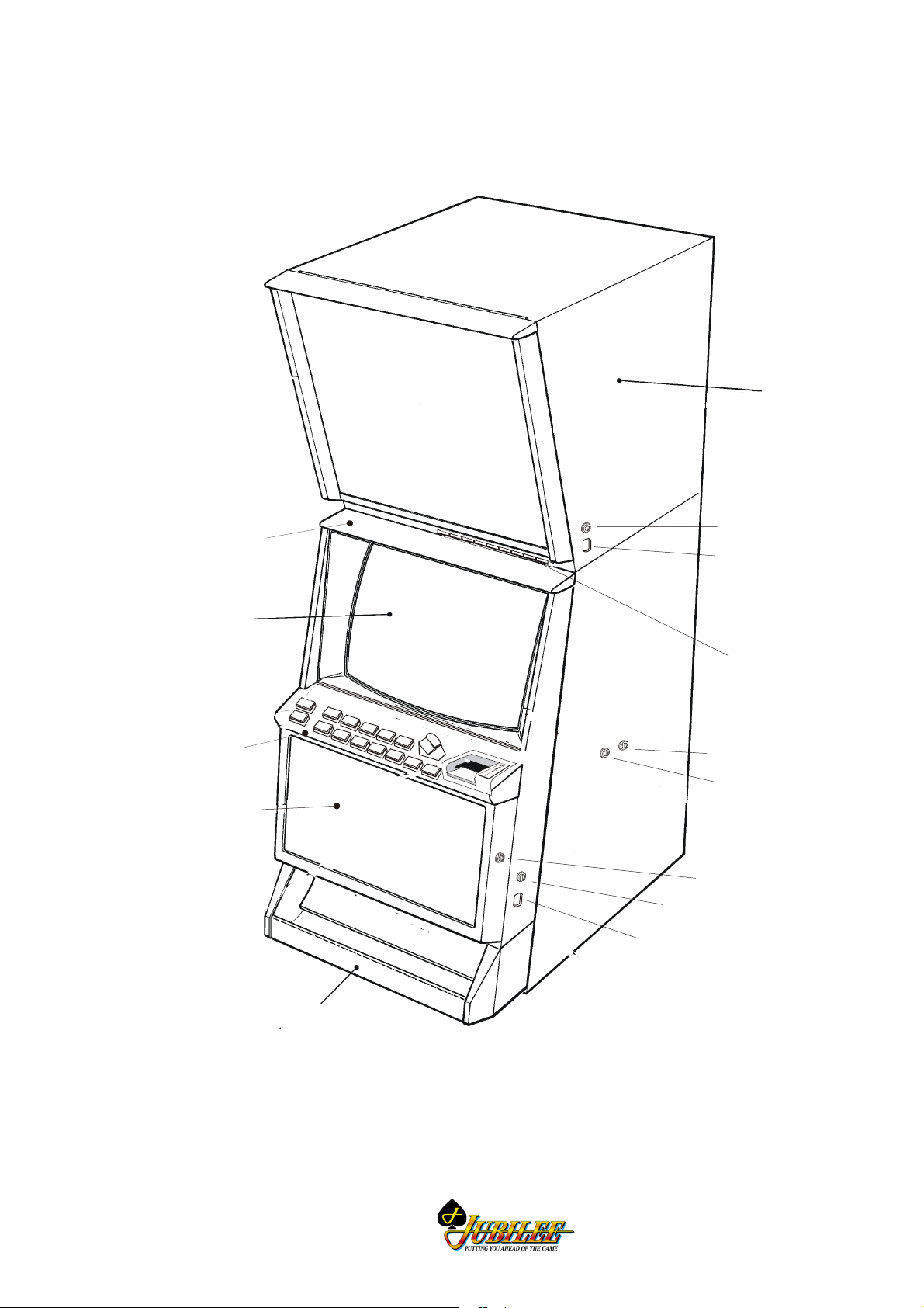
DOORS, FRONT PANELS &
DENOMINATION PATCHES
To p B o x
To p Tri m
Monitor
Mid Trim
Belly Panel
To p B o x Lo c k
To p Bo x L a t c h
Electromechanical
Meters
Jackpot Key Switch
Audit Key Switch
Belly Panel Lock
Main Door Lock
Main Door Latch
Revision 01
Coin Tray
I0126
Figure 1-1 Mk4/5XR Series Video Gaming Machine - External View
1-5
General Description NSW MK4/5 Video Service Manual
Machine Keys
The gaming machine requires keys for the following locks and switches to
establish effective security and correct operation. Refer to Figure 1-1 for lock and
keyswitch positions.
Note
A key may only be removed from its lock or
key switch after it has been returned to the
locked position.
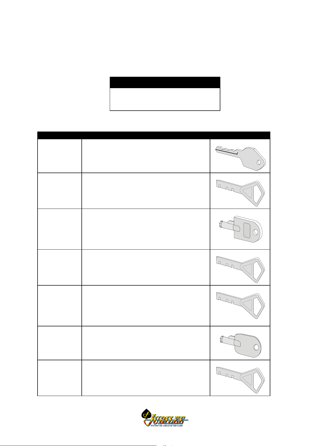
Table 1-2 Machine Key Types
Name Function Type
Audit Key
Switch
Enables entry to the Operator Mode Menu (see
Machine Modes).
Insert the Audit Key and turn it 90° clockwise.
I0004
Cabinet Door
Lock
Jackpot Reset
Key Switch also called the
Cancel Credit
Key Switch
Logic Cage
Lock (if fitted)
Bank Note
Acceptor
Cage Door
Lock(s)
(optional)
Bank Note
Stacker Door
Lock
Allows the operator to open the cabinet door.
Insert the cabinet door key and turn it 180°
clockwise, then lift the latch to release the door.
Allows the operator to reset the machine after a
machine fault has been corrected (see Machine
Modes).
Insert the Cancel Credit key, turn it 90° clockwise
then back again.
Allows the operator access to the PCB logic cage.
Insert the logic cage key and turn it 180°
clockwise.
Allows operator access to the bank note stacker.
Turn key 180° clockwise to open.
Allows the operator to remove the notes from the
stacker.
Insert the key and turn it 90° clockwise, open the
stacker door and remove the notes.
I0005I0005
I0006
I0005I0005
I0005I0005
I0007
Top Box Door
Lock
1-6
Allows the operator to open the top box.
Insert the top box key and turn it 180° clockwise,
then press in the top box latch pin release the
door.
I0005I0005
Revision 01
NSW MK4/5 Video Service Manual General Description
Belly Panel
Door Lock
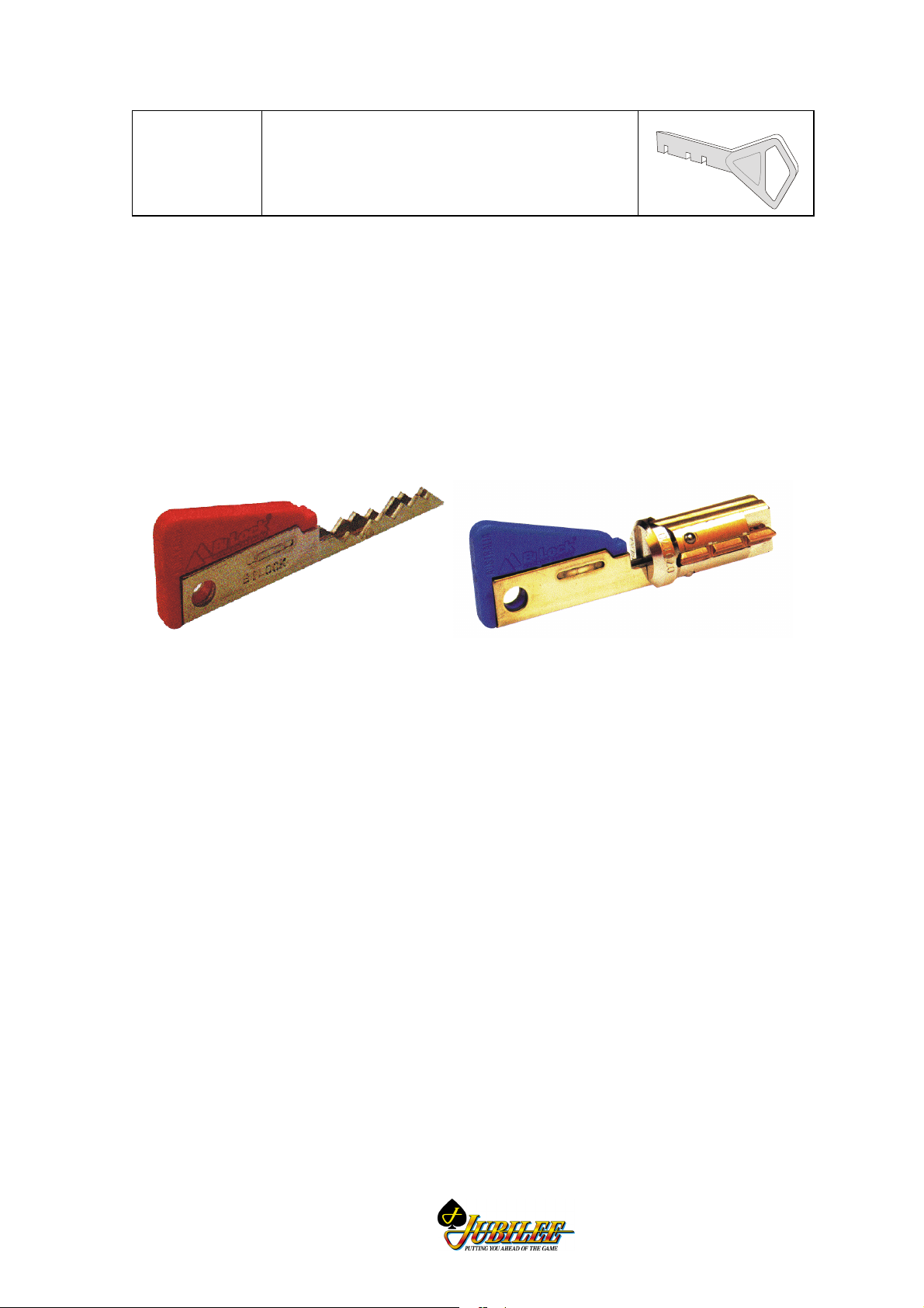
Bilock Locks
The gaming machines may be fitted with high-security Bilock camlocks and
switchlocks with a unique "U" shaped keyway (see Figure 1-2). The locks feature
the Quick Change Core facility whereby the keyed core of the lock is fitted
separate to the lock barrel. Locks may be rekeyed in a matter of seconds without
having to dismantle the lock assembly.
To remove a lock assembly, simply unscrew the large nut on the lock barrel and
pull out the lock assembly.
Allows the operator to open the belly panel door to
gain access to the bank note stacker. Insert the
key and turn it 180° clockwise.
I0005I0005
Bilock Key Quick Change Core
Figure 1-2 Bilock "U" Shaped Keyway and Quick Change Core Features
Revision 01
1-7

General Description NSW MK4/5 Video Service Manual
1.2 Basic Operation
The functions of the gaming machine are controlled by an advanced software and
hardware platform that provides operators with greater control over machine
functions and simplifies maintenance and machine setup. New games developed
with the software provide higher quality graphics, new sounds and a wider variety
of features.
All processing is carried out on the Main Board. The Main Board contains the
central processor and the game EPROMs which hold the software required for
game generation and video graphics. All data and control signals to and from the
Main Board are distributed by the Interface Board. The Interface Board also
distributes regulated low voltage power from the power control system.
The machine has two major modes of operation: Play mode and Operator mode.
The machine is in Play Mode when the cabinet door is closed and locked, the
Audit key switch is in the OFF position and there are no fault or lock-up
conditions.
The machine is in Operator Mode when the Audit key switch is in the ON
position. Operator Mode provides for a range of operational procedures, data
displays, and specific machine functions. Normal gameplay is disabled during
Operator Mode.
1.2.1 Play Mode
When in Play Mode, the machine:
• permits gameplay,
• operates security and audit features,
• runs self-checking and testing continuously,
• monitors and records gameplay activities continuously,
• displays comments and guidance for players, operators and technicians.
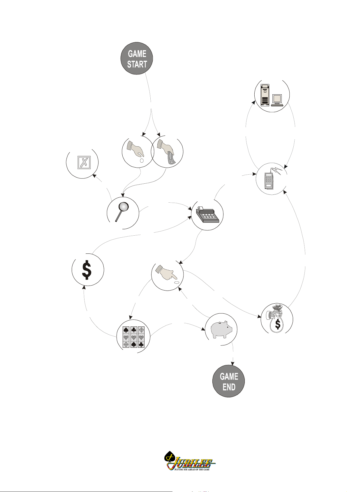
Basic machine operation in Play Mode is shown in Figure 1-3. Depending on the
machine configuration, credits may be registered by inserting coins, bank notes or
tokens. The machine has security features for screening the currency tendered to
ensure that only valid currency is accepted.
If the currency is accepted by the machine, the playbuttons on the mid trim
become active and flash. The player may then insert more currency, play a game
by pressing one of the flashing playbuttons, or have the machine return the current
credit total by pressing the COLLECT pushbutton. The player determines how
many credits to wager by pressing one of the BET playbuttons, and the BET meter
on the display screen shows the credits wagered.
1-8
Revision 01
NSW MK4/5 Video Service Manual General Description
A
Central
Processor
PLAYER INSERTS CREDITS
Invalid Currency
Returned To Player
Win Credits
To Be Added
Coin/Token
REJECT
Machine Checks
Currency Validity
ACCEPT
ADD
WIN
Player Presses
Selected Pushbutton
PLAY
Bank Note
Registers Credits
YES
Machine
AUDIT
DATA
COLLECT
UDIT DATA
CONTROL
INFORMATION
Communications
Interface
AUDIT
DATA
Revision 01
I0011
WIN
NO
WIN
Remaining
Machine Displays
Game Outcome
Figure 1-3 Basic Game Operation in Play Mode
Credits are Paid
to Player
Credit
NO
1-9
 Loading...