

Aristo AM-430TX User Manual

Electronic Emission Notices
Federal Communications Commission (FCC) Statement
This equipment has been tested and found to comply with the limits for a Class B digital
device, pursuant to Part 15 of FCC Rules. These limits are designed to provide reasonable
protection against harmful interference in a residential installation. This equipment
generates, uses and can radiate radio frequency energy and, if not installed and used in
accordance with instructions contained in this manual, may cause harmful interference
to radio and television communications. However, there is no guarantee that interference
will not occur in a particular installation.
If this equipment does cause harmful interference to radio or television reception, which
can be determined by turning the equipment off and on, the user is encouraged to try to
correct the interference by one or more of the following measures:
- RE-ORIENT OR RELOCATE THE RECEIVING ANTENNA
- INCREASE THE SEPARA TION BETWEEN THE EQUIPMENT AND THE RECEIVER
- CONNECT THE EQUIPMENT INTO AN OUTLET ON A CIRCUIT DIFFERENT FROM
THAT OF THE RECEIVER
- CONSULT THE DEALER OR AN EXPERIENCED AUDIO/TELEVISION
TECHNICIAN
NOTE: Connecting this device to peripheral devices that do not comply with Class
B requirements, or using an unshielded peripheral data cable, could also result
in harmful interference to radio or television reception.
1
The user is cautioned that any changes or modifications not expressly approved
by the party responsible for compliance could void the user’s authority to
operate this equipment.
To ensure that the use of this product does not contribute to interference,
it is necessary to use shielded I/O cables.
Copyright
This manual is copyrighted with all rights reserved. No portion of this manual may be copied or
reproduced by any means.
While every precaution has been taken in the preparation of this manual, no responsibility for
errors or omissions is assumed. Neither is any liability assumed for damages resulting from the
use of the information contained herein.
Trademarks
All brand names and registered trademarks mentioned are property of their respective owners.

2
Table of Contents
Hardware Configuration .......................................................................................... 3
Key Features ............................................................................................................ 3
Motherboard Layout (Model Code No. - 35827303)................................................ 5
Jumper Settings........................................................................................................ 6
Memory Configuration .............................................................................................. 10
BIOS Setup ................................................................................................................... 1 5
Main Menu ................................................................................................................ 15
Standard CMOS Setup ............................................................................................. 17
BIOS Features Setup ............................................................................................... 19
Chipset Features Setup ........................................................................................... 19
Integrated Peripherals .............................................................................................. 19
Supervisor/User Password Setting ......................................................................... 19
Power Management Setup....................................................................................... 20
PNP/PCI Configuration Setup .................................................................................... 20
Flash Update Procedure .......................................................................................... 2 0
Note to User
This manual is for use with both versions with or without the DIMM socket. If your
motherboard does not have a DIMM socket, ignore the DIMM socket on motherboard
layout and the respective DIMM configurations.

HARDWARE CONFIGURATION
The Intel® 430TX Pentium® PCI motherboard is based on the Intel® 430TX BGA Chipset.
The chipset is a highly integrated solution for a cost-effective and compact motherboard.
Features on-board include super-I/O, PCI bus master IDE(support ultra DMA 33MB/Sec),
PCI Ver 2.1 compliance, USB, support of Pentium CPUs running at 90, 100, 120, 133, 150,
166, 180, 200, 233MHz, Cyrix 6x86 CPUs AMD K5 and AMD K6 processors. DIMM and
SIMM sockets are provided onboard, allowing flexible installation of main memory. The
onboard pipelined burst cache further boosts the system performance.
Key Features
Processor
• ZIF Socket 7.
• Full support for the Intel® Pentium processor with MMX technology using socket
7.
• Supports 60MHz and 66MHz bus speed including all Pentium®
processors operating from 90MHz to 233MHz.
• Supports Cyrix 6x86 and AMD K5 and AMD K6 processors.
Cache
• The external cache policy is direct-mapped, write-back.
• 256KB or 512KB synchronous pipelined burst cache is supported.
System Memory
• 8M to 256MB
• A total of four 72-pin SIMM sockets and three 168-pin DIMM sockets.
• Both 5V Fast Page Mode and Extended Data Output (EDO) DRAM types are
supported by SIMM sockets.
• 3.3V SDRAM types supported by DIMM sockets.
3
Memory Organization
Four 72-pin SIMM Sockets
• System memory is divided into two banks. Each bank has two 72-pin SIMM slots.
• Supports Fast Page Mode (FPM), Extended Data Out (EDO) at , 60 and 70ns
speeds.
• Supports Symmetrical and Asymmetrical DRAM addressing.
• Memory size from 8M byte up to 256M byte.
• Supports single-density SIMMs of 512KBx32, 1MBx32, 2MBx32and 4MBx32
depth and 16MBx32 depth.
• Supports double-density SIMMs of 1MBx32, 2MBx32, 4MBx32 and 8MBx32 depth.
• Banks of different DRAM types and depths can be mixed.
Hardware Setup

4
Three 168-pin DIMM Sockets
• Supports Synchronous DRAM (SDRAM) at 66MHz.
• Supports Symmetrical and Asymmetrical DRAM addressing.
• Memory size from 8M byte up to 256M byte.
• Supports single-density DIMMs of 1MBx64, 2MBx64, 4MBx64 and 8MBx64 depth.
• Supports double-density DIMMs of 2MBx64, 4MBx64,8MBx64 and16MBx64 depth.
• Supports 3.3V SDRAM types.
On-Board I/O
• Two enhanced IDE channel supporting up to four ATA or ATA2 or Ultra DMA IDE
devices.
• Bus Master IDE function enhances multitasking performance.
• One ECP/EPP parallel port (via a header).
• Two 16550-compatible UART serial ports (via a header).
• One floppy port supporting two FDDs of 360KB, 720KB, 1.2MB, 1.44MB or
2.88MB.
• Two USB ports (via a header).
• Factory option to have one standard AT keyboard port or one PS/2 keyboard
port(not both).
• PS/2 mouse port (via a header ).
• Infrared (IrDA) support (via a header).
System BIOS
• 1MB or 2MB flash BIOS supporting PnP, APM, ATAPI and Windows® 95.
• Auto detects and supports LBA hard disks with formatted capacities up to
8.4GB.
• Easily upgradable by end-user.
Plug-and-Play
• Supports plug-and-play specification 1.1.
• Plug-and-play for DOS, Windows® 3.X as well as Windows® 95.
• Fully steerable PCI interrupts.
Expansion Slots
• 4 PCI bus master slots (rev . 2.1 compliant, with 1 PCI slot sharing with 1 ISA slot).
• 3 ISA slots (1 ISA slot sharing with 1 PCI slot).
Power Management
• APM specification 1.2 compliant.
• Support auto display off and hard disk standby.
• Activity monitoring for non-APM power management.
• Support external SMI push-button.
• comply to the Energy star “Green PC” program.
• Advanced system Config and Power Interface(ACPI).
Technical Reference Booklet
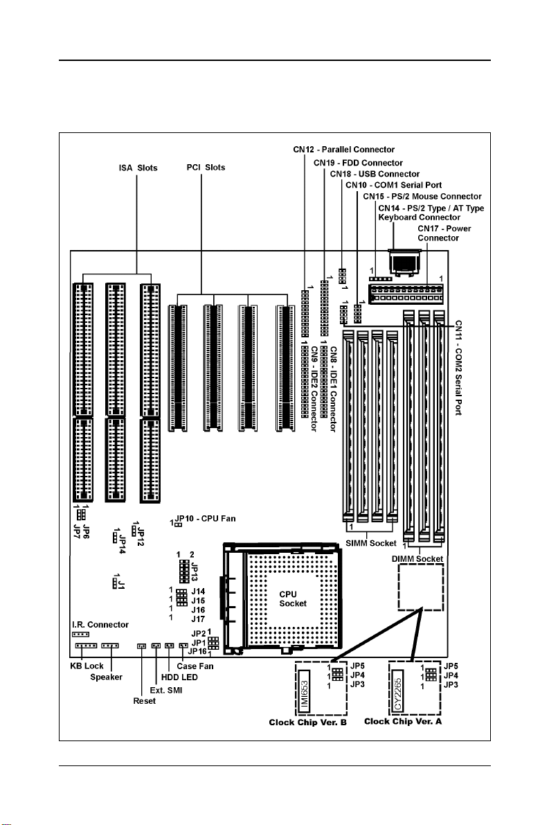
Motherboard Layout (Model Code No. - 35827303)
The following diagrams show the relative positions of the jumpers, connectors, major
components and banks on the motherboard.
5
Hardware Setup
6
Jumper Settings
This chapter explains how to configure the motherboard’s hardware. Before using your
computer, make sure all jumpers and DRAM modules are set correctly. Refer to this
chapter whenever in doubt.
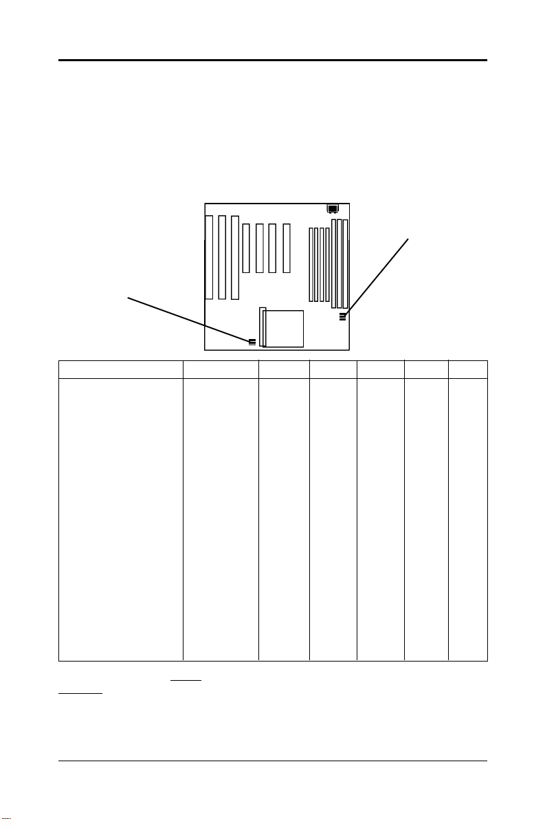
JP1, JP2, JP3, JP4, JP5 - CPU Type Selection (Clock
Generator Ver. A)
You can locate three headers JP3, JP4 and JP5 (of the same color) for clock generator
ver A.
JP5
JP4
JP3
JP2
JP1
JP16
CPU Type & Speed Bus Clock JP1 JP2 JP3 JP4 JP5
Intel Pentium-90 60MHz 1-2 1-2 1-2 1-2 2-3
Intel Pentium-100 66MHz 1-2 1-2 2-3 1-2 1-2
Intel Pentium-120 60MHz 1-2 2-3 1-2 1-2 2-3
Intel Pentium-133 66MHz 1-2 2-3 2-3 1-2 1-2
Intel Pentium-150 60MHz 2-3 2-3 1-2 1-2 2-3
Intel Pentium-166 66MHz 2-3 2-3 2-3 1-2 1-2
Intel Pentium-180 60MHz 2-3 1-2 1-2 1-2 2-3
Intel Pentium-200 66MHz 2-3 1-2 2-3 1-2 1-2
Intel Pentium-233 66MHz 1-2 1-2 2-3 1-2 1-2
Cyrix 6x86-P150+ 60MHz 1- 2 2-3 1-2 1-2 2-3
Cyrix 6x86-P166+ 66MHz 1- 2 2-3 2-3 1-2 1-2
AMD-K5-PR90 60MHz 1-2 1-2 1-2 1-2 2-3
AMD-K5-PR100 66MHz 1-2 1-2 2-3 1-2 1-2
AMD-K5-PR120 60MHz 1-2 1-2 1-2 1-2 2-3
AMD-K5-PR133 66MHz 1-2 1-2 2-3 1-2 1-2
AMD-K5-PR166 66MHz 2-3 2-3 2-3 1-2 1-2
AMD-K5-PR200 66MHz 2-3 1-2 2-3 1-2 1-2
AMD-K6-PR2-166 66MHz 2-3 2-3 2-3 1-2 1-2
AMD-K6-PR2-200 66MHz 2-3 1-2 2-3 1-2 1-2
AMD-K6-PR2-233 66MHz 1-2 1-2 2-3 1-2 1-2
JP16 is reserved for future AMD K6 processors. Simply leave JP16 OPEN for all
existing Intel, Cyrix, AMD K5 and AMD K6 processors. This motherboard is
compatible with Cyrix 6x86 CPU but must be Revision 2.7 and newer. Please
contact your CPU supplier for details on identification of Cyrix 6x86 CPU
revisions.
Technical Reference Booklet
 Loading...