

Page 1
Transceiver Compatibility and Interoperability
Overview
Arista optical transceivers and cables offer deployment flexibility and cost optimized network connectivity.
Arista transceivers and cables are all hot-swappable pluggable devices, compliant with industry standards, and
certified on all Arista platforms unless otherwise stated. This document provides a technical reference guide on
compatibility, interoperability, software support, and physical attributes of Arista transceivers and cables.
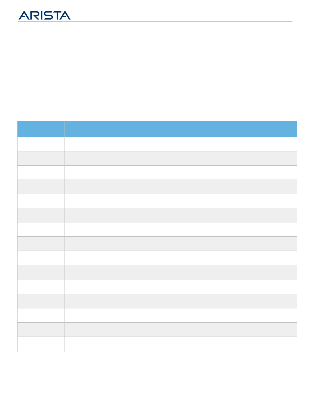
Arista EOS Support
All Arista products run on Arista EOS software. Tables 1-8 below provide the minimum version of EOS that is
required for each of the transceivers and cables. Note that Arista switches have their own minimum EOS release
requirement and Tables 1-8 should be read in conjunction with the EOS release notes.
Part Number
Description
Minimum EOS Ver#
CAB-O-O-400G-xM
400GBASE-CR8 OSFP to OSFP Twinax Copper Cable (1 to 3 meters)
4.23.0
CAB-O-2Q-400G-xM
400GBASE-CR8 OSFP to 2 x 200GBASE-CR4 QSFP Twinax Copper Cable (1 to 3 meters)
4.23.0
CAB-O-2Q-200G-xM
200GBASE-CR8 OSFP to 2 x 100GBASE-CR4 QSFP Twinax Copper Cable (1 to 3 meters)
4.23.0
CAB-O-4Q-400G-xM
400GBASE-CR8 OSFP to 4 x 100GBASE-CR2 QSFP Twinax Copper Cable (1 to 3 meters)
4.23.0
CAB-O-4Q-200G-xM
200GBASE-CR8 OSFP to 4 x 50GBASE-CR2 QSFP Twinax Copper Cable (1 to 3 meters)
4.23.0
CAB-O-8S-200G-xM
200GBASE-CR8 OSFP to 8 x 25GBASE-CR SFP Twinax Copper Cable (1 to 3 meters)
4.23.0
H-O400-4Q100-xM*
400GBASE-CR8 OSFP to 4x 100GBASE-CR4 QSFP Twinax Active Copper Cable (1 to 5 meters)
4.25.2
AOC-O-O-400G-xM
400GbE OSFP to OSFP Active Optical Cable (1 to 30 meters)
4.23.0
OSFP-400G-SR8
400GBASE-SR8 OSFP Transceiver, up to 100m over parallel OM4 MMF
4.23.0
OSFP-400G-DR4
400GBASE-DR4 OSFP Transceiver, up to 500m over parallel SMF
4.23.2
OSFP-400G-XDR4
4x 100GBASE-FR (or 400G-XDR4) OSFP Transceiver, up to 2km over parallel SMF
4.24.0
OSFP-400G-PLR4
4x 100GBASE-LR (or 400G-PLR4) OSFP transceiver, up to 10km over parallel SMF
4.25.2
OSFP-400G-FR4
400GBASE-FR4 OSFP Transceiver, up to 2km over duplex SMF
4.24.0
OSFP-400G-LR4
400GBASE-LR4 OSFP Transceiver, up to 10km over duplex SMF
4.25.2
OSFP-400G-2FR4
400GBASE-2FR4 OSFP Transceiver, up to 2km over 2 pairs of duplex SMF
4.23.0
Table 1: Minimum EOS Version for 400G OSFP Transceivers and Cables
*
The Arista 400G OSFP to 4x QSFP100 active copper cables allow a 400G OSFP port (with 8x 50G PAM-4 electrical lanes) to connect to 4x QSFP100 ports (with
4x 25G NRZ electrical lanes per QSFP). A gearbox inside the QSFP end of the cable implements the 2x 50G PAM-4 to 4x 25G NRZ conversion.
Page 2
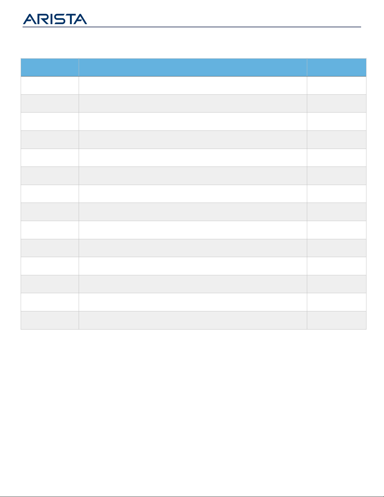
Part Number
Description
Minimum EOS Ver#
CAB-D-D-400G-xM
400GBASE-CR8 QSFP-DD to QSFP-DD Twinax Copper Cable (1 to 2.5 meters)
4.23.0
CAB-D-2Q-400G-xM
400GBASE-CR8 QSFP-DD to 2 x 200GBASE-CR4 QSFP Twinax Copper Cable (1 to 2.5 meters)
4.23.0
CAB-D-2Q-200G-xM
200GBASE-CR8 QSFP-DD to 2 x 100GBASE-CR4 QSFP Twinax Copper Cable (1 to 2.5 meters)
4.23.0
CAB-D-4Q-400G-xM
400GBASE-CR8 QSFP-DD to 4 x 100GBASE-CR2 QSFP Twinax Copper Cable (1 to 2.5 meters)
4.23.0
CAB-D-4Q-200G-xM
200GBASE-CR8 QSFP-DD to 4 x 50GBASE-CR2 QSFP Twinax Copper Cable (1 to 2.5 meters)
4.23.0
CAB-D-8S-200G-xM
200GBASE-CR8 QSFP-DD to 8 x 25GBASE-CR SFP Twinax Copper Cable (1 to 2.5 meters)
4.23.0
H-D400-4Q100-xM*
400GBASE-CR8 QSFP-DD to 4x 100GBASE-CR4 QSFP Twinax Active Copper Cable (1 to 5 meters)
4.25.2
AOC-O-O-400G-xM
400GbE OSFP to OSFP Active Optical Cable (1 to 30 meters)
4.23.0
QDD-400G-SR8
400GBASE-SR8 QSFP-DD Transceiver, up to 100m over parallel OM4 MMF
4.24.0
QDD-400G-DR4
400GBASE-DR4 QSFP-DD Transceiver, up to 500m over parallel SMF
4.24.0
QDD-400G-XDR4
4x 100GBASE-LR (or 400G-XDR4) QSFP-DD transceiver, up to 3km over parallel SMF
4.24.0
QDD-400G-PLR4
4x 100GBASE-LR (or 400G-PLR4) QSFP-DD transceiver, up to 10km over parallel SMF
4.25.2
QDD-400G-FR4
400GBASE-FR4 QSFP-DD Transceiver, up to 2km over duplex SMF
4.24.0
QDD-400G-LR4
400GBASE-LR4 QSFP-DD Transceiver, up to 10km over duplex SMF
4.25.2
Table 2: Minimum EOS Version for 400G QSFP-DD Optics and Cables
*
The Arista 400G QSFP-DD to 4x QSFP100 active copper cables allow a 400G OSFP port (with 8x 50G PAM-4 electrical lanes) to connect to 4x QSFP100 ports
(with 4x 25G NRZ electrical lanes per QSFP). A gearbox inside the QSFP end of the cable implements the 2x 50G PAM-4 to 4x 25G NRZ conversion.
Page 3
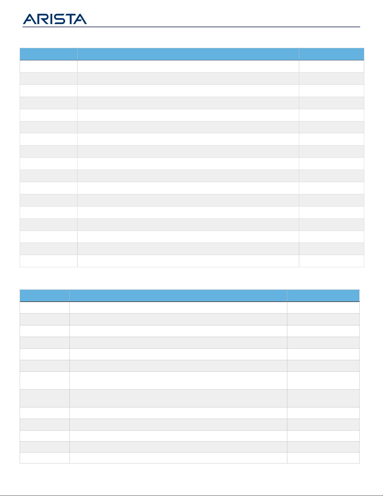
Part Number
Description
Minimum EOS Ver#
CAB-Q-S-yM
4 x 10GbE QSFP+ to 4 x SFP+ Twinax Copper Cable (y = 0.5 to 5 meter)
All supported EOS releases
CAB-Q-Q-yM
40GBASE-CR4 QSFP+ to QSFP+ Twinax Copper Cable (y = 0.5 to 5 meters)
All supported EOS releases
AOC-Q-Q-40G-yM
QSFP+ to QSFP+ 40GbE Active Optical Cable (y = 3 to 100 meters)
4.13.0
QSFP-40G-SR4
40GBASE-SR4 QSFP+ Optic, up to 100m over OM3 MMF or 150m over OM4 MMF
All supported EOS releases
QSFP-40G-XSR4
40GBASE-XSR4 QSFP+ Optic, up to 300m over OM3 MMF or 400m over OM4 MMF
4.11.1
QSFP-40G-SRBD
40GBASE-BIDI Bidirectional QSFP+ Optic, up to 100m/150m over duplex OM3/OM4 MMF
4.15.2
QSFP-40G-SRBD-R
40GBASE-BIDI Receiver only QSFP+, up to 100m over duplex OM3 or 150m over duplex
OM4 MMF
4.15.2
QSFP-40G-UNIV
40GBASE-UNIV QSFP+ Optic, up to 150m over duplex OM3/OM4 and
500m over duplex SMF
4.14.0
QSFP-40G-LRL4
40GBASE-LRL4 QSFP+ Optic, up to 1km over duplex SMF
4.13.3
QSFP-40G-LR4
40GBASE-LR4 QSFP+ Optic, up to 10km over duplex SMF
All supported EOS releases
QSFP-40G-PLRL4
40GBASE-PLRL4 QSFP+ Optic, up to 1km over parallel SMF (4x10G LR up to 1km)
4.13.0
QSFP-40G-PLR4
40GBASE-PLR4 QSFP+ Optic, up to 10km over parallel SMF (4x10G LR up to 10km)
4.13.0
QSFP-40G-ER4*
40GBASE-ER4 QSFP+ Optic, up to 40km over duplex SMF
4.14.5
Part Number
Description
Minimum EOS Ver#
CAB-Q-Q-100G-yM
100GBASE-CR4 QSFP to QSFP Twinax Copper Cable (y = 1 to 5 meters)
4.15.2
CAB-Q-4S-100G-yM
100GBASE-CR4 QSFP to 4 x 25GBASE-CR SFP Twinax Copper Cable (y = 1 to 5 meters)
4.18.0
CAB-Q-2Q-100G-yM
100GBASE-CR4 QSFP to 2 x 50GBASE-CR2 QSFP Twinax Copper Cable (y = 1 to 5 meters)
4.22.1
AOC-Q-Q-100G-yM
QSFP to QSFP 100GbE Active Optical Cable (y = 3 to 30 meters)
4.15.2
QSFP-100G-SR4
100GBASE-SR4 QSFP transceiver, up to 70m over parallel OM3 or 100m over OM4 MMF
4.15.2
QSFP-100G-XSR4
100GBASE-XSR4 QSFP transceiver, up to 150m over parallel OM3 or 300m over OM4 MMF
4.21.0
QSFP-100G-SWDM4
100GBASE-SWDM4 QSFP transceiver, up to 70m over OM3 or 100m over OM4 duplex MMF
4.20.1
QSFP-100G-SRBD
100GBASE-BIDI QSFP transceiver, up to 70m/100m over OM3/OM4 duplex MMF
4.20.1
QSFP-100G-PSM4
100GBASE-PSM4 QSFP Optics Module, up to 500m over parallel SMF
4.15.3
QSFP-100G-CWDM4
100GBASE-CWDM4 QSFP Optics Module, up to 2km over duplex SMF
4.15.5
QSFP-100G-XCWDM4
100GBASE-XCWDM4 QSFP Optics Module, up to 10km over duplex SMF
4.24.2
QSFP-100G-LRL4
100GBASE-LRL4 QSFP Optics Module, up to 2km over duplex SMF
4.15.2
QSFP-100G-DR
100GBASE-DR QSFP Optics Module, up to 500m over duplex SMF
4.21.3
QSFP-100G-FR
100GBASE-FR QSFP Optics Module, up to 2km over duplex SMF
4.22.1
QSFP-100G-LR
100GBASE-LR QSFP Optics Module, up to 10km over duplex SMF
4.23.1
QSFP-100G-LR4
100GBASE-LR4 QSFP Optics Module, up to 10km over duplex SMF
4.15.2
QSFP-100G-ERL4*
100GBASE-ERL4 QSFP Optics Module, up to 40km over duplex SMF
4.20.1
Table 3: Minimum EOS Version for 100G QSFP Transceivers and Cables
* Proper optical attenuation is required for shorter links to protect the receiver from permanent damage
Table 4: Minimum EOS Version for 40G QSFP+ Transceivers and Cables
Page 4
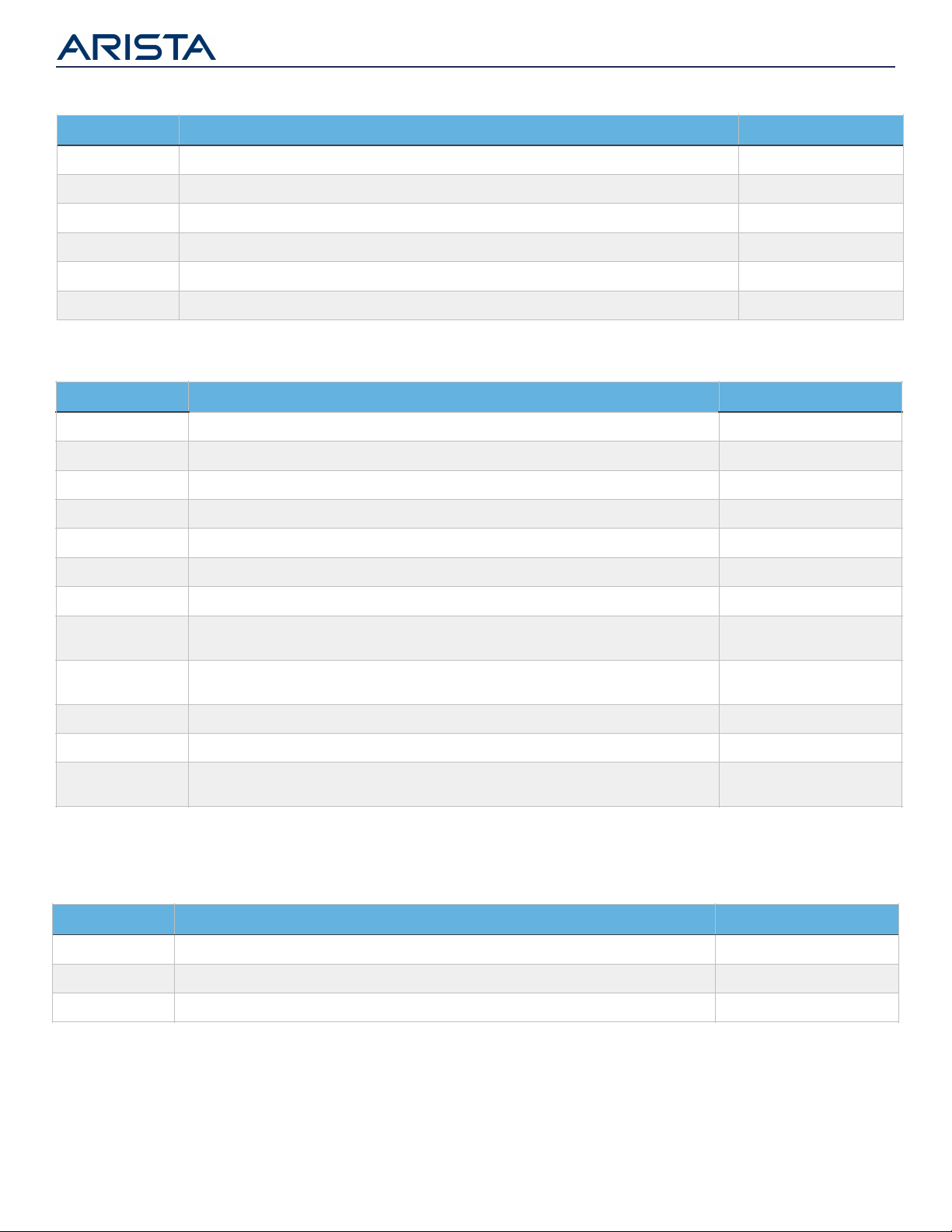
Part Number
Description
Minimum EOS Ver#
CAB-SFP-SFP-yM
10GBASE-CR SFP+ Cable (y = 0.5 to 5 meters)
All supported EOS releases
AOC-S-S-10G-yM
SFP+ to SFP+ 10GbE Active Optical Cable (y = 3 to 30 meters)
4.14.0
SFP-10G-T *
10GBASE-T Copper (RJ45) Transceiver, up to 30m over Cat6a cable
4.23.2
SFP-10G-SRL
10GBASE-SRL SFP+ Transceiver, up to 100m over OM3 MMF or 150m over OM4 MMF
All supported EOS releases
SFP-10G-SR
10GBASE-SR SFP+ Transceiver, up to 300m over OM3 MMF or 400m over OM4 MMF
All supported EOS releases
SFP-10G-LRL
10GBASE-LRL SFP+ Transceiver, up to 1km over duplex SMF
All supported EOS releases
SFP-10G-LR
10GBASE-LR SFP+ Transceiver, up to 10km over duplex SMF
All supported EOS releases
SFP-10G-ELRBD-U
SFP-10G-ELRBD-D
10GBASE-ERLBD SFP+ Transceiver, uplink / downlink, up to 30km over single ber SMF
4.21.3
SFP-10G-ERBD-U**
SFP-10G-ERBD-D **
10GBASE-ERBD SFP+ Transceiver, uplink / downlink, up to 40km over single ber SMF
4.21.3
SFP-10G-ER**
10GBASE-ER SFP+ Transceiver, up to 40km over duplex SMF
All supported EOS releases
SFP-10G-ZR**
10GBASE-ZR SFP+ Transceiver, up to 80km over duplex SMF
All supported EOS releases
SFP-10G-DZ-T**
10GBASE-DWDM Tunable SFP+ Optics Module, Full C-Band 50 GHz ITU Grid, up to 80km
over duplex SMF
4.15.2
Table 6: Minimum EOS Version for 10G SFP+ Transceivers and Cables
Part Number
Description
Minimum EOS Ver#
SFP-1G-SX
1000BASE-SX SFP Transceiver
All supported EOS releases
SFP-1G-LX
1000BASE-LX SFP Transceiver
All supported EOS releases
SFP-1G-T
100/1000BASE-T SFP Copper (RJ45) Transceiver
All supported EOS releases
Table 7: Minimum EOS Version for SFP Transceivers
Part Number
Description
Minimum EOS Ver#
CAB-S-S-25G-yM
25GBASE-CR SFP Cable (y = 1 to 5 meters)
4.18.0
AOC-S-S-25G-yM
SFP to SFP 25GbE Active Optical Cable (y = 3 to 30 meters)
4.18.0
SFP-25G-SR
25GBASE-SR SFP Optics Module, up to 70m over OM3 MMF or 100m over OM4 MMF
4.18.0
SFP-25G-MR-XSR
Dual rate 10/25GBASE-XSR SFP Optics Module, up to 200m over OM3 or 300m over OM4 MMF
4.24.2
SFP-25G-LR
25GBASE-LR SFP Optics Module, up to 10km over duplex SMF
4.18.0
SFP-25G-MR-LR
Dual rate 10/25GBASE-MR-LR SFP Optics Module, up to 10km over duplex SMF
4.24.2
Table 5: Minimum EOS Version for 25G SFP Transceivers
* SFP-10G-T supported on limited platforms listed in table 8. Additional platform support will be added over time.
** Proper optical attenuation is required for shorter links to protect the receiver from permanent damage.
Page 5

Part Number
Bail Latch or Pull Tab
Termination/Connector Type
Fiber Type to be used
SFP-1G-SX
Bail Latch
Duplex LC
MMF
SFP-1G-LX
Bail Latch
Duplex LC
MMF and SMF
SFP-1G-T
Bail Latch
RJ-45
Twisted pair, Category 5
CAB-SFP-SFP-xM
Pull Tab
Pre-terminated. Assembly includes both ends of transceivers and cable fused
together
AOC-S-S-10G-xM
Pull Tab
SFP-10G-T
Bail Latch
RJ-45
Twisted pair, Category 6a
SFP-10G-SR / SRL
Bail Latch
Duplex LC
MMF
SFP-10G-ZR / ER / LR / LRL
Bail Latch
Duplex LC
SMF
SFP-10G-ELRBD-U
SFP-10G-ELRBD-D
Bail Latch
Simplex LC
SMF
SFP-10G-ERBD-U
SFP-10G-ERBD-D
Bail Latch
Simplex LC
SMF
SFP-10G-DZ-T
Bail Latch
Duplex LC
SMF
CAB-S-S-25G-yM
Pull Tab
Pre-terminated. Assembly includes both ends of transceivers and cable fused
together
AOC-S-S-25G-yM
Pull Tab
SFP-25G-SR / MR-XSR
Bail Latch
Duplex LC
MMF
SFP-25G-LR / MR-LR
Bail Latch
Duplex LC
SMF
* Please refer to the Arista Transceivers datasheet for additional information on reach for each fiber/cable type (http://www.arista.com/assets/data/pdf/Datasheets/Transceiver-
Data-Sheet.pdf )
Table 9: Physical attributes of 1/10/25G SFP Transceivers
Platform Family
Platform(s)
Comments
720XP Series
720XP-24ZY4
Supported on all SFP25 ports
720XP-24Y6
720XP-48Y6
720XP-48ZC2
720XP-96ZC2
7050X Series
7050SX3-48YC8 & 7050SX3-48C8
Supported on all SFP25 ports and SFP+ ports
7050SX3-96YC8
Supported on SFP25 ports 1-48 (top two rows), 50-106 (bottom row), with
remaining SFP25 boards populated with 2W max non BASE-T modules.
Supported on front-to-rear airow (-F) models only.
7060X Series
7060SX2-48YC6
Supported on all SFP25 ports, front-to-rear airow (-F) only
7280R Series
7280SR2A-48YC6 and 7280SR2-48YC6
Supported on all SFP25 ports
7280SR2K-48C6
24x SFP25 ports and front-to-rear airow (-F) only
7280SR3-48YC8
Supported on all SFP25 ports
7300 Series
7300X3-48YC4
Supported on all SFP25 ports
7500R Series
7500R2AK-48YCQ
Supported on all SFP+ ports
Table 8: Platform Support for SFP-10G-T
Connector and Cable type
Tables 9-12 provides the physical attributes of Arista transceivers and cables for easy product identification and
lists the correct cable and connector type for termination*.
Page 6

Part Number
Bail Latch or Pull Tab
Termination/Connector Type
Fiber Type to be used
CAB-Q-S-xM
Pull Tab
N/A
N/A
CAB-Q-Q-xM
Pull Tab
N/A
N/A
AOC-Q-Q-40G-xM
Pull Tab
N/A
N/A
QSFP-40G-SR4
Pull Tab
MPO-12
MMF
QSFP-40G-XSR4
Pull Tab
MPO-12
MMF
QSFP-40G-SRBD
Pull Tab
Duplex LC
MMF
QSFP-40G-LRL4
Pull Tab
Duplex LC
SMF
QSFP-40G-LR4
Pull Tab
Duplex LC
SMF
QSFP-40G-PLRL4
Pull Tab
MPO-12
SMF
QSFP-40G-PLR4
Pull Tab
MPO-12
SMF
QSFP-40G-UNIV
Pull Tab
Duplex LC
MMF and SMF
QSFP-40G-ER4
Pull Tab
Duplex LC
SMF
Table 10: Physical attributes of 40G QSFP+ Transceivers and Cables
Part Number
Bail Latch or Pull Tab
Termination/Connector Type
Fiber Type to be used
CAB-Q-Q-100G-yM
Pull Tab
N/A
N/A
AOC-Q-Q-100G-xM
Pull Tab
N/A
N/A
QSFP-100G-SR4
Pull Tab
MPO-12
MMF
QSFP-100G-XSR4
Pull Tab
MPO-12
MMF
QSFP-100G-SWDM4
Pull Tab
Duplex LC
MMF
QSFP-100G-SRBD
Pull Tab
Duplex LC
MMF
QSFP-100G-PSM4
Pull Tab
MPO-12
SMF
QSFP-100G-CWDM4
Pull Tab
Duplex LC
SMF
QSFP-100G-XCWDM4
Pull Tab
Duplex LC
SMF
QSFP-100G-LRL4
Pull Tab
Duplex LC
SMF
QSFP-100G-DR
Pull Tab
Duplex LC
SMF
QSFP-100G-FR
Pull Tab
Duplex LC
SMF
QSFP-100G-LR
Pull Tab
Duplex LC
SMF
QSFP-100G-LR4
Pull Tab
Duplex LC
SMF
QSFP-100G-ERL4
Pull Tab
Duplex LC
SMF
QSFP-100G-DZ2-xx
Pull Tab
Duplex LC
SMF
CFP2-100G-XSR10
Bail Latch
MPO-24
MMF
CFP2-100G-LR4
Bail Latch
Duplex LC
SMF
CFP2-100G-ER4
Bail Latch
Duplex LC
SMF
MXP - Multi-Speed Port
N/A
MPO-24
MMF
Table 11: Physical attributes of 100G QSFP, CFP2 and MXP (Embedded) Transceivers
Page 7

Part Number
Bail Latch or Pull Tab
Termination/Connector Type
Fiber Type to be used
CAB-O-O-400G-xM
Pull Tab
N/A
N/A
CAB-O-2Q-400G-xM
Pull Tab
N/A
N/A
CAB-O-2Q-200G-xM
Pull Tab
N/A
N/A
CAB-O-4Q-400G-xM
Pull Tab
N/A
N/A
CAB-O-4Q-200G-xM
Pull Tab
N/A
N/A
CAB-O-8S-200G-xM
Pull Tab
N/A
N/A
H-O400-4Q100-xM
Pull Tab
N/A
N/A
AOC-O-O-400G-xM
Pull Tab
N/A
N/A
OSFP-400G-SR8
Pull Tab
MPO-16 (APC)
MMF
OSFP-400G-DR4
Pull Tab
MPO-12
SMF
OSFP-400G-XDR4
Pull Tab
MPO-12
SMF
OSFP-400G-PLR4
Pull Tab
MPO-12
SMF
OSFP-400G-FR4
Pull Tab
Duplex LC
SMF
OSFP-400G-PLR4
Pull Tab
Duplex LC
SMF
OSFP-400G-2FR4
Pull Tab
Dual CS
SMF
CAB-D-D-400G-xM
Pull Tab
N/A
N/A
CAB-D-2Q-400G-xM
Pull Tab
N/A
N/A
CAB-D-2Q-200G-xM
Pull Tab
N/A
N/A
CAB-D-4Q-400G-xM
Pull Tab
N/A
N/A
CAB-D-4Q-200G-xM
Pull Tab
N/A
N/A
CAB-D-8S-200G-xM
Pull Tab
N/A
N/A
H-D400-4Q100-xM
Pull Tab
N/A
N/A
QDD-400G-SR8
Pull Tab
MPO-16 (APC)
MMF
QDD-400G-DR4
Pull Tab
MPO-12
SMF
QDD-400G-XDR4
Pull Tab
MPO-12
SMF
QDD-400G-PLR4
Pull Tab
MPO-12
SMF
QDD-400G-FR4
Pull Tab
Duplex LC
SMF
QDD-400G-LR4
Pull Tab
Duplex LC
SMF
Table 12: Physical attributes of 400G OSFP and QSFP-DD Transceivers and Cables
Page 8

Direct attach copper cables
Twinax copper Direct attach cables (also known as DACs) offer the most cost effective connectivity solution for
short distance intra-rack (server to switch) and inter-rack (switch to switch across adjacent racks) links. Table 13-14
provides a summary of Arista’s DAC cables and their attributes
10G SFP+ to SFP+
25G SFP to SFP
40G QSFP+ to
QSFP+
100G QSFP to QSFP
Arista Part Number
CAB-SFP-SFP-yM
CAB-S-S-25G-yM
CAB-Q-Q-yM
CAB-Q-Q-100G-yM
Cable Type
Twinax
Twinax
Twinax
Twinax
Supported Standards
10GBASE-CR
25GBASE-CR
40GBASE-CR4
100GBASE-CR4
Available lengths (meters)
0.5, 1, 1.5, 2, 2.5, 3, 5
1, 2, 3, 5
0.5, 1, 2, 3, 5
0.5, 1, 1.5, 2, 2.4, 3, 5
Wire AWG
0.5 to 3 meter: 30 AWG
5 meter: 24 AWG
1, 2 meter: 30 AWG
3, 5 meter: 26 AWG
1, 2, 3 meter: 30 AWG
5 meter: 24 AWG
1, 2, 3 meter: 30 AWG
5 meter: 26 AWG
Cable characteristic
impedance
100 Ohm Differential
100 Ohm Differential
100 Ohm Differential
100 Ohm Differential
Bend Radius
0.5 to 3 meter: 25mm
5 meter: 30mm
1, 2, 3, 5 meter: 30mm
1, 2, 3 meter: 35mm
5 meter: 50mm
1, 2, 3 meter: 45mm
5 meter: 60mm
Table 13: Attributes of copper direct attach cables
40G QSFP+ to 4x10G SFP+
break-out cable
100G QSFP to 4x25G SFP
break-out cable
Arista Part Number
CAB-Q-S-yM
CAB-Q-4S-100G-yM
Cable Type
Twinax
Twinax
Supported Standards
40GBASE-CR4, 10GBASE-CR
100GBASE-CR4, 25GBASE-CR
Available lengths (meters)
0.5, 1, 2, 3, 5
1, 2, 3, 5
Wire AWG
1, 2, 3 meter: 30 AWG
5 meter: 24 AWG
1, 2 meter: 30 AWG
3, 5 meter: 26 AWG
Cable characteristic impedance
100 Ohm Differential
100 Ohm Differential
Bend Radius
40G QSFP+ Side
0.5, 1, 2, 3 meter: 35mm
5 meter: 50mm
10G SFP+ Side
0.5, 1, 2, 3 meter: 25mm
5 meter: 30mm
100G QSFP Side
1, 2 meter: 45 mm
3, 5 meter: 60mm
25G SFP Side
1, 2, 3, 5 meter: 30mm
Table 14: Attributes of copper direct attach breakout cables
Digital Optical Monitoring (DOM)
Arista EOS provides enhanced monitoring capabilities for continuous performance monitoring and
troubleshooting of optical transceivers. Some of the key monitor parameters are Temperature Monitor, Voltage
Monitor, Transmitter and Receive power and Transmitter Bias current. Unless otherwise stated, DOM capabilities
are supported on all Arista AOCs and optical transceivers. The Arista 40G AOC cables, AOC-Q-Q-40G-xM, support
all regular DOM features except for Tx optical power.
Page 9

SFP-10G-
LRL
SFP-10G-
LR
SFP-25-MR-LR
@10G
QSFP-40G-
PLRL4
QSFP-40G-
PLR4
QSFP-40G-
UNIV
QSFP-40G-
LRL4
QSFP-40G-
LR4
SFP-10G-LRL
1km
1km
1km*
1km
1km
N/A
SFP-10G-LR
10km
10km*
1km
10km
SFP-25-MR-LR @10G
10km*
1km*
10km*
QSFP-40G-PLRL4
1km
1km
QSFP-40G-PLR4
10km
QSFP-40G-UNIV
N/A
500m
N/A
QSFP-40G-LRL4
1km
1km
QSFP-40G- LR4
10km
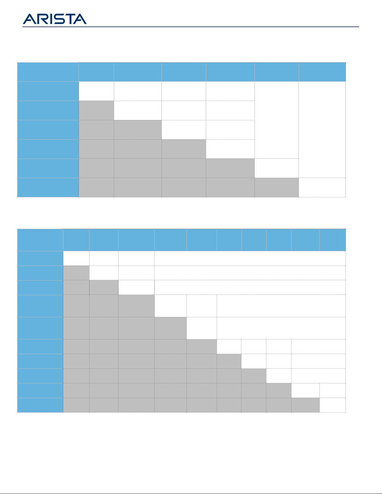
Interoperability
Arista transceivers and cables are based on industry standards and/or Multi-Source Agreements (MSA) and
therefore interoperable with the relevant standards and MSA transceivers. Guidance on the interoperability of the
Arista transceivers is detailed in Tables 15 - 19.
SFP-10G-SRL
SFP-10G-SR
SFP-25G-MR-XSR
@10G
QSFP-40G-SR4
QSFP-40G-XSR4
QSFP-40G-SRBD
QSFP-40G-
UNIV
SFP-10G-SRL
100m (OM3)
150m (OM4)
100m (OM3)
150m (OM4)
100m (OM3)*
150m (OM4)*
100m (OM3)
150m (OM4)
100m (OM3)*
150m (OM4)*
N/A
N/A
SFP-10G-SR
300m (OM3)
400m (OM4)
300m (OM3)*
400m (OM4)*
100m (OM3)
150m (OM4)
300m (OM3)*
400m (OM4)*
SFP-25G-MR-XSR
@10G
300m (OM3)
400m (OM4)
100m (OM3)
150m (OM4)
300m (OM3)
400m (OM4)
QSFP-40G-SR4
100m (OM3)
150m (OM4)
100m (OM3)
150m (OM4)
QSFP-40G-XSR4
300m (OM3)
400m (OM4)
QSFP-40G-SRBD
100m (OM3)
150m (OM4)
QSFP+ UNIV
N/A
150m (OM3)
150m (OM4)
Table 16: 10G/40G Transceiver interoperability for single-mode ber
Table 15: 10G/40G Transceiver interoperability for multi-mode ber
* Optical attenuation may be required for short links. Refer to Optics Modules and Cables datasheet for optical specications.
Page 10
SFP-25-SR
SFP-25G-MR-XSR
QSFP-100G-SR4
QSFP-100G-XSR4
QSFP-100G-
SWDM4
QSFP-100G-SRBD
SFP-25-SR
70m (OM3)
100m (OM4)
70m (OM3)
100m (OM4)
70m (OM3)
100m (OM4)
70m (OM3)
100m (OM4)
N/A
N/A
SFP-25G-MR-XSR
200m (OM3)
300m (OM4)
70m (OM3)
100m (OM4)
150m (OM3)
300m (OM4)
QSFP-100G-SR4
70m (OM3)
100m (OM4)
70m (OM3)
100m (OM4)
QSFP-100G-XSR4
150m (OM3)
300m (OM4)
QSFP-100G-SWDM4
70m (OM3)
100m (OM4)
QSFP-100G-SRBD
70m (OM3)
100m (OM4)
Table 17: 25G/100G Transceiver interoperability for multi-mode ber
SFP-25G-
LR
SFP-25G-
MR-LR
QSFP-100G-
PSM4
QSFP-100G-
CWDM4
QSFP-100G-
XCWDM4
QSFP-
100G-DR
QSFP-
100G-FR
QSFP-
100G-LR
QSFP-
100G-LRL4
QSFP-
100G-LR4
SFP-25G-LR
10km
10km
500m
N/A
SFP-25G-MR-LR
10km
500m
N/A
QSFP-100G-PSM4
500m
N/A
QSFP-100G-
CWDM4
2km
2km
N/A
QSFP-100G-
XCWDM4
10km
N/A
QSFP-100G-DR
500m
500m
500m
N/A
QSFP-100G-FR
2km
2km
N/A
QSFP-100G-LR
10km
N/A
QSFP-100G-LRL4
2km
2km
QSFP-100G-LR4
10km
Table 18: 25G/100G Transceiver interoperability for single-mode ber
* Optical attenuation may be required for short links. Refer to Optics Modules and Cables datasheet for optical specications.
Page 11

100G-DR
100G-FR
100G-LR
100G-
CWDM4
100G-
XCWDM4
400G-
DR4
400G-
XDR4
400G-
PLR4
400G-
FR4
400G-
LR4
400G-
2FR4
100G-DR
500m
500m
500m
N/A
N/A
500m
500m
500m
N/A
N/A
N/A
100G-FR
2km
2km
N/A
N/A
500m
2km
2km
N/A
N/A
N/A
100G-LR
10km
N/A
N/A
500m
2km
10km
N/A
N/A
N/A
100G-
CWDM4
2km
2km
N/A
N/A
N/A
N/A
N/A
2km*
100G-
XCWDM4
10km
N/A
N/A
N/A
N/A
N/A
2km*
400G-DR4
500m
500m
500m
N/A
N/A
N/A
400G-
XDR4
2km
2km
N/A
N/A
N/A
400G-
PLR4
10km
N/A
N/A
N/A
400G-FR4
2km
2km*
N/A
400G-LR4
10km
N/A
400G-
2FR4
2km
Table 20: 100G/400G Transceiver interoperability for Single-mode ber
QSFP-40G-SR4
QSFP-40G-XSR4
QSFP-100G-SR4
QSFP-100G-XSR4
OSFP & QDD 400G-
SR8
QSFP-40G-SR4
100m (OM3)
150m (OM4)
100m (OM3)
150m (OM4)
N/A
N/A
70m (OM3)*
100m (OM4)*
QSFP-40G-XSR4
400m (OM4)
N/A
N/A
70m (OM3)*
100m (OM4)*
QSFP-100G-SR4
100m (OM4)
100m (OM4)
70m (OM3)*
100m (OM4)*
QSFP-100G-XSR4
300m (OM4)
70m (OM3)*
100m (OM4)*
OSFP & QDD 400G-SR8
70m (OM3)*
100m (OM4)*
Table 19: 40G/100G/400G Transceiver interoperability for multi-mode ber
* Optical attenuation may be required for short links. Refer to Optics Modules and Cables datasheet for optical specications.
Page 12

Fiber Cleaning
Contaminated fiber optic connectors often lead to degraded performance and costly, but preventable, failures.
Industry studies show that the number one cause of link failure is a contaminated or dirty connector or fiber. To
ensure proper performance and reliability care must be taken with the installation and maintenance of
removable fiber connectors. For recommendations and best practices on fiber connection cleaning, please refer
to the Arista Application Note at https://www.arista.com/assets/data/pdf/Fiber-Cleaning-App-Note.pdf
Laser Eye Safety
Arista optical transceivers are classified as CLASS 1 laser eye safety compliant per IEC 60825-1: 2007. Class 1 laser
products emit invisible laser radiation; it is strongly recommended not to stare into beams or view directly with
optical instruments.
Installing and Removing Transceivers and Cables
This section describes how to install and remove optical transceivers and cables. An ESD-preventive wrist or
ankle strap should be used before installing or removing transceivers and cables to protect the device from
damage.
Installation procedure for Transceivers with Bail Latch
Step 1: Close the bail latch before inserting the transceiver
Step 2: Line-up the transceiver with the switch port and slide it into the port
Step 3: Firmly push the transceiver to ensure it is completely seated and secured in the receptacle on the switch
Step 4: Connect clean fiber cables to the transceiver. Alternatively cover the optical port with clean dust covers
Removal procedure for Transceivers with Bail Latch
Step 1: Disconnect all interface cables from the transceiver
Step 2: Open the bail latch on the transceiver with index finger
Step 3: Grasp the transceiver between thumb and index finger and carefully remove it from the switch port
Installation procedure for Transceivers with Pull-tab
Step 1: Line-up the transceiver with the switch port and slide it into the port
Step 2: Firmly push the transceiver to ensure it is completely seated and secured in the receptacle on the switch
Step 3: Connect clean fiber cables to the transceiver. Alternatively cover the optical port with clean dust covers
Removal procedure for Transceivers with Pull-tab
Step 1: Disconnect all interface cables from the transceiver
Step 2: Grasp the Pull-tab with thumb and index finger and gently pull to remove the transceiver
Page 13

Warranty
The Arista pluggables and cables include a one-year limited hardware warranty, which covers parts, repair, or replacement with a 10
business day turn-around after the unit is received.
Service and Support
Support services including next business day and 4-hour advance hardware replacement are available. For service depot locations,
please see: http://www.arista.com/en/service
Headquarters
5453 Great America Parkway
Santa Clara, California 95054
408-547-5500
Support
support@arista.com
408-547-5502
866-476-0000
Sales
sales@arista.com
408-547-5501
866-497-0000
Copyright 2021 Arista Networks, Inc. The information contained herein is subject to change without notice. Arista, the
Arista logo and EOS are trademarks of Arista Networks. Other product or service names may be trademarks or service marks
of others.
www.arista.com
Feb 22, 2021 03-0029-12
 Loading...