

Page 1
Talk to us. We listen.
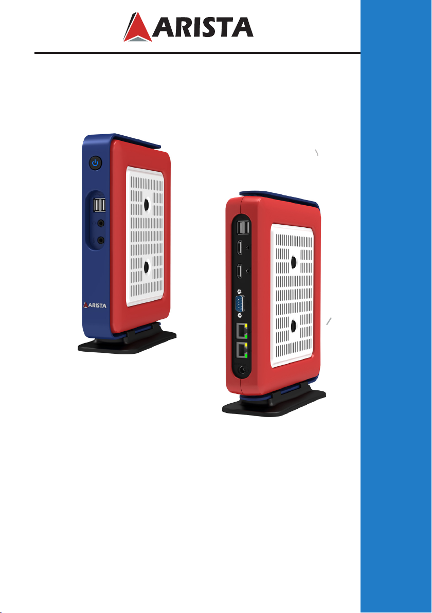
AP-3500-E01 Oce Thin Client
USER MANUAL
This manual is a user guide for AP-3500-E01 Oce Thin Client. It includes
detailed description about how to install and operate the product. Arista
Corporation recommends users to read through the entire manual and
follow instructions to avoid any kind of obscurity in using the product.
For any questions or support, please call us at 1.877.827.4782 Monday
through Friday 8:00am to 5:00PM Pacic Time.
Publication date: 2016/10/25
Version No.: V2.2
Page 2

Product safety precautions
It is recommended to follow the instructions and safety precautions listed below. This
manual should be saved for future references and use.
• Relative humidity: 25%~80%
• Storage temperature: -20oC to 60oC(-4F to 140F)
• Operation temperature: 0~50oC(32F to 122F)
• Unplug the unit when not in use for an extended period of time.
• Consult a service technician if the unit does not operate normally when you have
followed the instructions in this manual.
• Do not attempt to repair this product yourself. Always get a qualified service
technician to carry out adjustments or repairs.
• Do not place heavy objects on the unit.
• Always use the power cord supplied with this unit. For any reason a different
powercordhastobeusedwiththisunit, it should be certied by local and national
standards and used under guidance of authorized technician.
• Never use a faulty power cord with this unit. Please contact the manufacturer or
nearest authorized repair service right away for a replacement if damaged power
cord is received.
• The power supply cord is used as the main disconnect device. Ensure that the socket
outlet is easily accessible after installation.
• Overloaded AC outlets, extension cords, frayed power cords, and broken plugs are
extremelydangerous.Theymay,andcan,resultinanelectricalshockorrehazard.
Call an authorized service technician for any replacements.
• Hands must be dry when plugging the power cord into an AC outlet to prevent
electrical shock. Do not damage the power cord by disassembling, bending, pulling
orexposingittoheatasitmaycauseareorelectricalshock.
• Make sure to completely insert the power plug into an AC outlet. Insecure
connectionscancauseare.
• Ensure that the power source is grounded correctly.
• Unplug the unit if cleaning is needed. The unit may be wiped down with a dry or
slightlydampclothwhenthepoweriso.
Important: Read all the contents of this instruction manual carefully before
using the AP-3500-E01 Oce Thin Client.
2
Page 3

Contents
Contents
Product safety precautions ................................................................................................2
Contents ...............................................................................................................................3
Chapter 1 Welcome .........................................................................................................4
Features..........................................................................................................................4
Product specications ..................................................................................................5
Unpacking ......................................................................................................................6
Chapter 2 Basics.................................................................................................................7
Product overview.......................................................................................................7
Physical dimensions ....................................................................................................9
Chapter 3 Connections ...................................................................................................10
Pins in the Serial port (COM1)...................................................................................11
Mounting the Thin Client............................................................................................12
Connecting to a display............................................................................................15
Connecting to keyboard or mouse..............................................................................15
Connecting to network............................................................................................16
Connecting earphones or speaker..............................................................................16
Connecting the power supply.............................................................................17
Installing memory module/expansion card..........................................................18
Clearing CMOS data....................................................................................................22
Chapter 4 BIOS Setup.......................................................................................................23
Introduction....................................................................................................23
Entering the setup..............................................................................................24
Main Menu..........................................................................................26
Advanced Menu............................................................................................27
Chipset Menu....................................................................................33
Security Menu................................................................................................37
Boot Menu................................................................................................38
Save&Exit Menu.........................................................................................39
Chapter 5 Appendix.........................................................................................................40
Care and Maintenance ...............................................................................................40
Product Limited Warranty..........................................................................................41
Disposal and Recycling Information.....................................................................46
Disclaimer and Copyright Notice ..............................................................................46
3
Page 4

Features
Arista AP-3500-E01 thin client is a lightweight computer that is purpose-built for remote
access to a server (typically cloud or desktop virtualization environments). Thin clients
occur as components of a broader computing infrastructure, where many clients share
their computations with a server or server farm. The server-side infrastructure makes use
of cloud computing software such as application virtualization, hosted shared desktop
(HSD) or desktop virtualization (VDI). This combination form is known as cloud based
system,wheredesktopresources are centralized intooneor more data centers. Benets
of centralized access are optimization of hardware resources, reduced maintenance and
more security.
• Intel E3845 1.91GHz ATOM CPU
• Up to 8GB DDR3 SO-DIMM Memory
• Dual Gigabit LAN
• SATA DOM for Storage Option
• Mini PCIe Expansion Slot
• ACP Enabled, PXE Boot
• Desktop or VESA Mount Available
4
Page 5
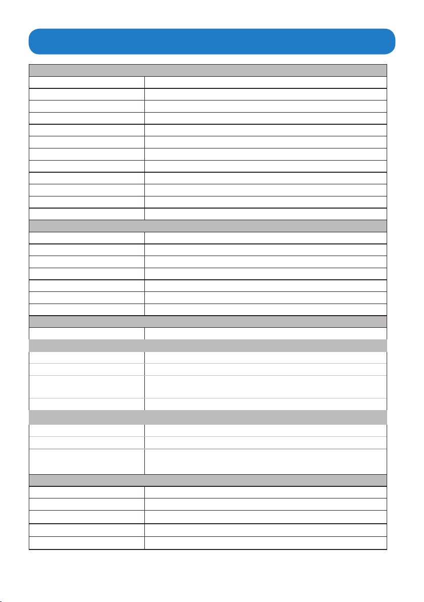
Product specications
System
CPU Intel E3845 1.91GHz ATOM CPU
Chipset (By CPU)
Memory Up to 8GB DDR3 SO-DIMM
Video controller Intel Gen7 Intel Graphics DX 11, OGL3.2
Video interface Dual HDMI
Storage option SATA DOM, 2.5" HDD, 2.5" SSD
Compactash N/A
Keyboard/Mouse USB
Audio Mic In, Line Out
Watchdog Timer N/A
Remote Boot ACP, PXE
Expansion Slot Mini PCIe x 1, CFast card connector x1
I/O Communication
USB port 1 x USB 3.0, 3 x USB 2.0
Serial port 1 x RS-232/422/485
IEEE 1394 N/A
LAN 2 x Gigabit
Parallel N/A
Power button 1 x Power button
Power 1x DC-IN power(12V, 1.05A)
Operating system
OS Support Windows 7 & up
Power / Thermal Specs.
Power requirement ( Max ) 12VDC/1.05A
Power consumption 13W
Recommended power
supply
Heat dissipation 43 BTU/hr
Physical information
Mounting
Net Weight 2.75Lbs / 1.2 Kg
Physical Dimension
(W x H x D)
Environmental information
Operating temperature 0~35°C (32~95°F)
Storage temperature -20~60OC [-4~140F]
Relative humidity 10% to 95% (non-condensing)
IP/NEMA Rating N/A
Certication FCC, CE, UL 60950-1
18W
Desktop, VESA Mount option
2.80 x 9.30 x 7.17 inch
70.5 x 236.5 x 182.0 mm
5
Page 6
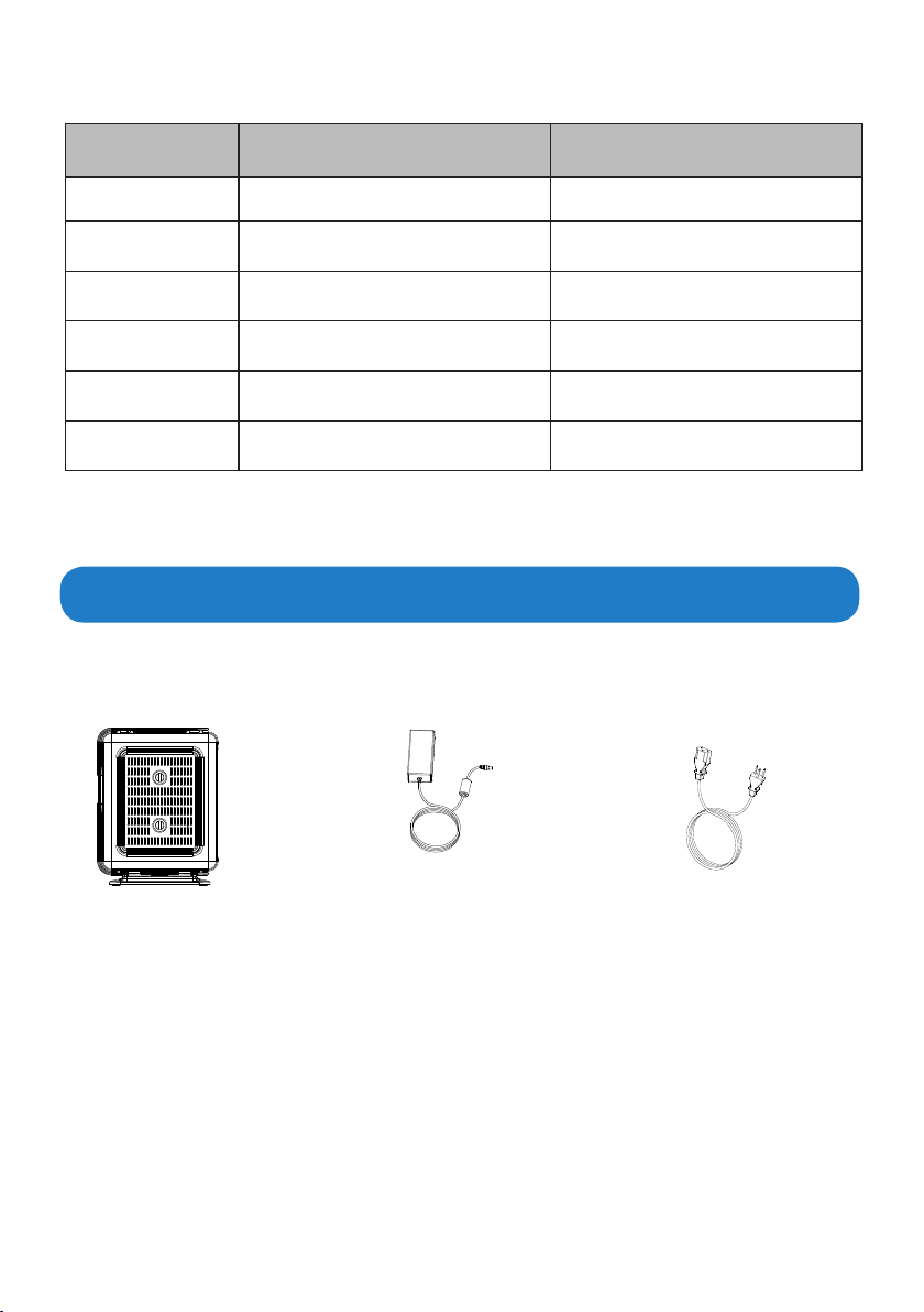
Options AP-3500-E01-003 AP-3500-E01-P03
CPU E3845 ATOM CPU E3845 ATOM CPU
Memory 4GB DDR 4GB DDR
Storage N/A N/A
Remote Boot ACP Enabled PXE
Power Supply 110/220VAC Input 110/220VAC Input
Operating System N/A N/A
Ordering Information
Unpacking
The unit is shipped with items listed below, inspect them carefully to make sure there is no
damage and all the items are available with your shipment.
AP-3500-E01 Thin Client x1 AC/DC power adapter x1 AC power cable x1
6
Page 7
Chapter 2 Basics
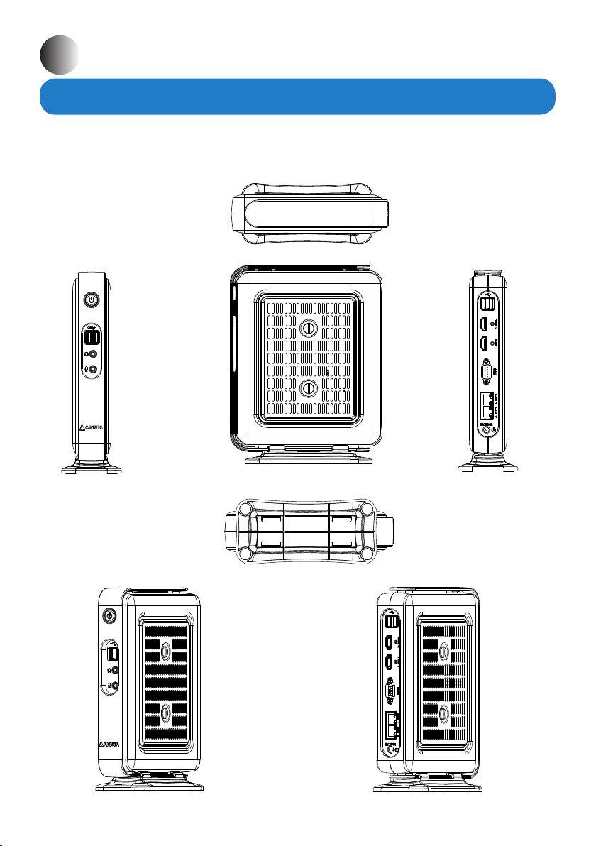
Product overview
AP-3500-E01 Oce Thin Client
Top
Side
Side
Front
Bottom
7
Page 8
1
5
2
3
4
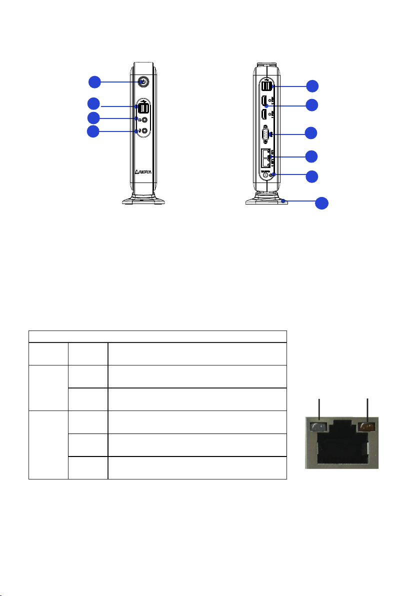
1. Power button 6. 2 x HDMI ports
2. 2 x USB ports 7. COM port
3. Earphone/Headphone jack 8. 2 x RJ45 LAN ports
4. Microphone jack 9. DC 12V/3A power jack
5. 2 x USB ports 10. Desktop stand base(removable)
LED Indications on the LAN port
Status Description
Activity
LED
O No network connection
On Data transmission activity
6
7
8
9
10
Speed LED Activity LED
Speed
LED
O Data transmission at the rate of 10Mbps
Orange Data transmission at the rate of 1Gbps
Green Data transmission at the rate of 100Mbps
8
Page 9
Physical dimension
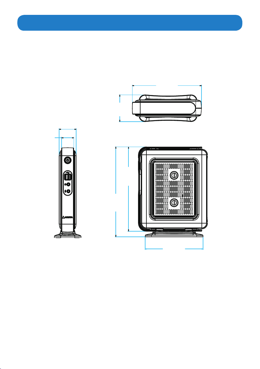
Thediagramsbelowshow the physical and specic dimensionsoftheAP-3500-E01 Thin
Client.
AP-3500-E01 Oce Thin Client
182.0mm
7.17"
70.5mm
44.6mm
1.76"
32.0mm
1.26"
2.77"
222.0mm
8.74"
236.5mm
9.31"
152.2mm
5.99"
9
Page 10
Chapter 3 Connections
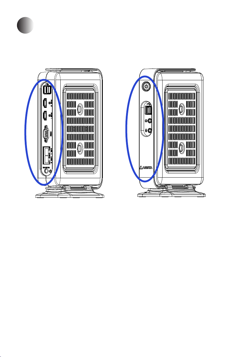
This section describes the connections/connectors available on the AP-3500-E01OceThin
Client.
Connectors are located on the side of AP-3500-E01 Thin Client.
10
Page 11
Pins in the serial port (COM1)
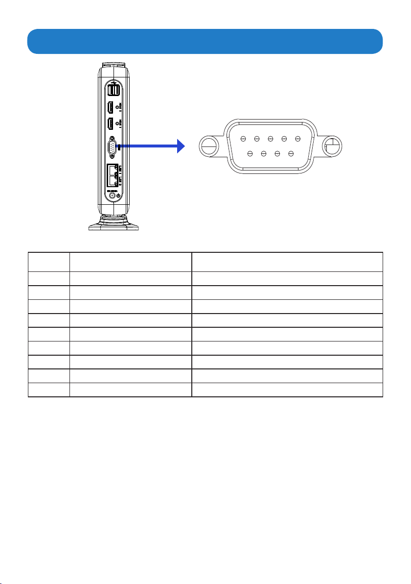
1 2 3 4 5
6 7 8 9
Pin NO. Denition(RS-232 mode) Denition(RS-422/RS-485 mode)
1 DCD, data carrier detect TX-, Transmit data ground (RS-422/RS-485)
2 RXD, Receive data TX+, Transmit data(RS-422/RS-485)
3 TXD, Transmit data RX+, Receive data (RS-422)
4 DTR, Data terminal ready RX-, Receive data ground (RS-422)
5 GND, Signal ground GND, Signal ground
6 DSR, Data set ready N.C.
7 RTS, Request to send N.C
8 CTS, Clear to send N.C
9 Ring-IN, Ring indicator N.C.
Note:
COM1 port is available for RS-232/RS-422/RS-485 Mode.
11
Page 12
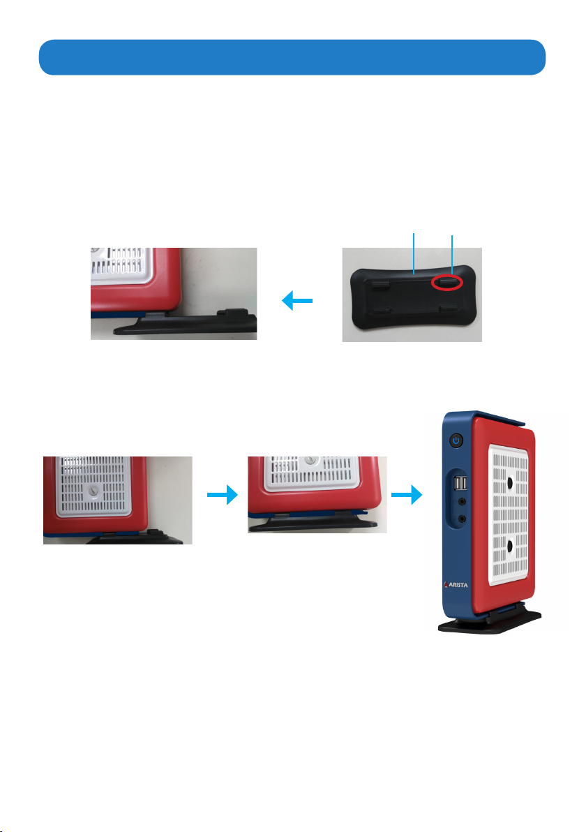
Mounting the Thin Client
Desktop mounting
The AP-3500-E01 Office Thin Client can be directly placed on a shelf or table by using
desktop stand base(supplied with the unit).
Please follow the steps shown in the diagram below:
Step1.
Place the bottom side ofAP-3500-E01 Oce Thin Client within the place on the
desktop stand base where there are four mounting clips.
Desktop Stand base
Step2.
SlidetheDesktopstandbasealongwiththeAP-3500-E01OceThinClientbottom
sideuntilthefourmountingclipsonthestandbasermlylocktheunit.
Mounting clip
12
Page 13
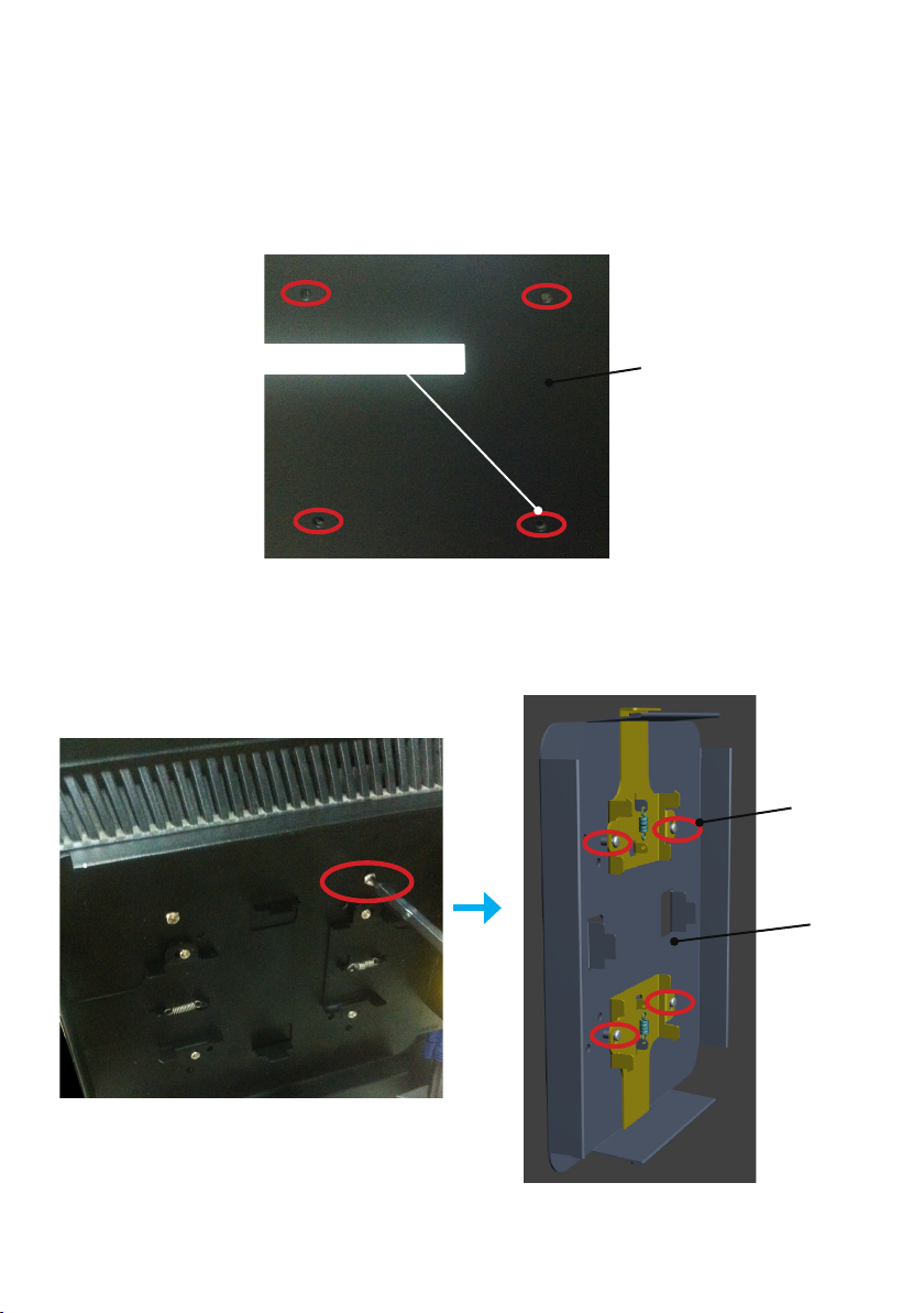
VESA mounting
You can also mount the AP-3500-E01OceThinClient onto a display. For display mount,
VESA mounting brackets and screws are available (sold separately).
Please follow the steps shown in the diagram below:
Step1.
Asshowninthegurebelow,ndthefourscrewholespredrilledatthebackofthe
display.
Screw holes
Step2.
Align the four mounting screw holes on the AP-3500-E01 VESA bracket with the
Display back panel
screw holes on the display.Tighten the four screws with a screw driver to x the VESA
bracket onto the display.
Mounting
screw
VESA
bracket
13
Page 14
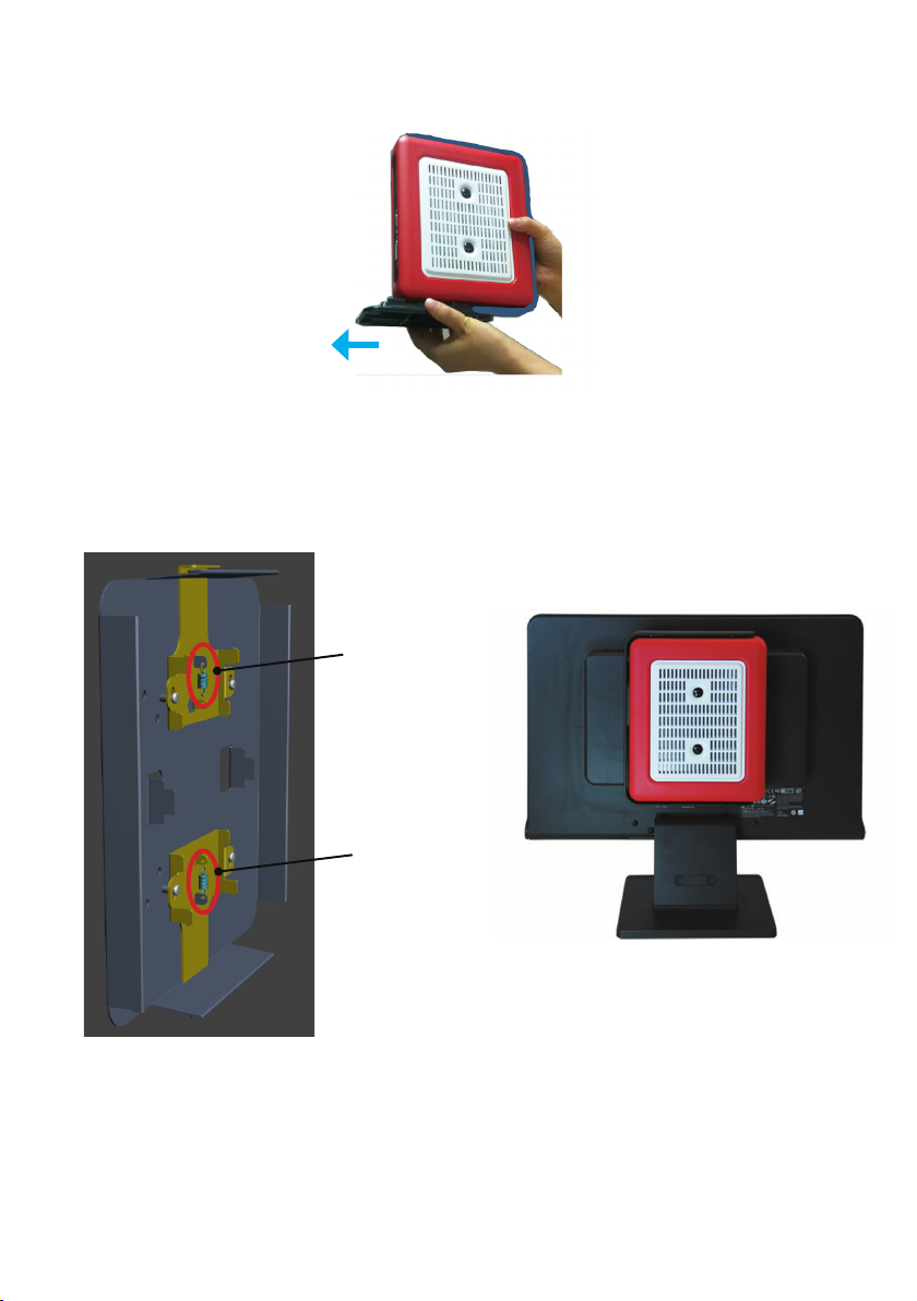
Step3.
If the AP-3500-E01OceThinClient is desktop mounted, please slide the desktop
stand base out to remove it from the unit.
Step4.
Snag the white bottom base of the AP-3500-E01 Oce Thin Client with the two
Spring hooks on the VESA bracket installed on the display. Make sure the AP-3500-E01
OceThinClientiscorrectlyandsecurelyseatedontothedisplay.
Spring hook
Spring hook
14
Page 15
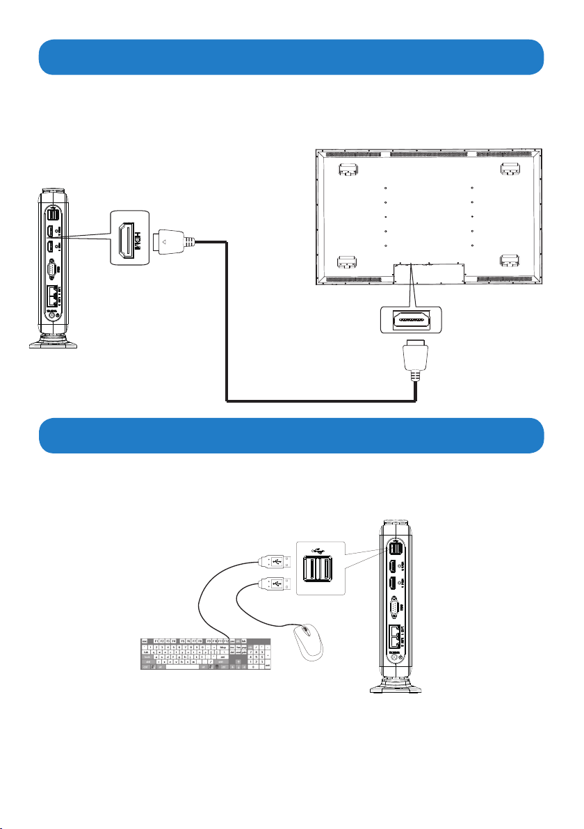
Connecting to a display
Connecting to a display through HDMI port
• Connectoneend of the HDMI cabletotheHDMI port of theAP-3500-E01 OceThin
Client. Connect the other end of the HDMI cable to the HDMI port of a display.
AP-3500-E01
Display
HDMI port
HDMI port
HDMI cable(not supplied)
Connecting to keyboard and mouse
•InsertaUSBkeyboardandaUSBmouse(not supplied) to AP-3500-E01OceThinClient
for controlling on the computer.
USB port
AP-3500-E01
Keyboard
Mouse
15
Page 16
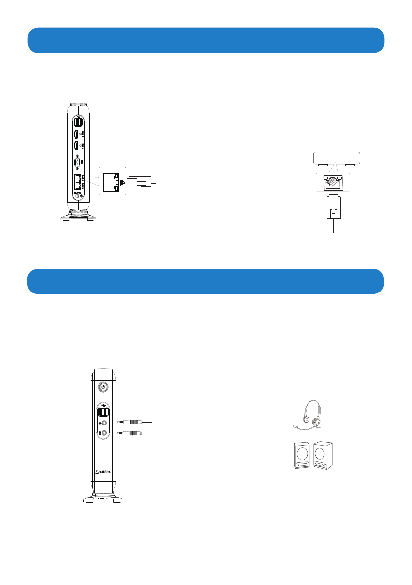
Connecting to network
• Connectoneend of the RJ45LAN cable to theLANport of theAP-3500-E01 Oce
Thin Client. Connect the other end of the RJ45 LAN cable to the LAN port of a modem.
AP-3500-E01
LAN port
RJ45 LAN cable(not supplied)
LAN port
Modem
Connecting earphones or speaker
• Connect the earphone end of the audio cable to the Earphone jack of the AP-3500-E01
OceThinClient.Connect the microphone endof the audio cabletothe Microphone
jack of the AP-3500-E01 Office Thin Client. Also, you can connect to a speaker by
connectingtotheEarphonejackoftheAP-3500-E01OceThinClient.
AP-3500-E01
earphone/headpone
3.5mm audio cable(not supplied)
16
Speaker
Page 17
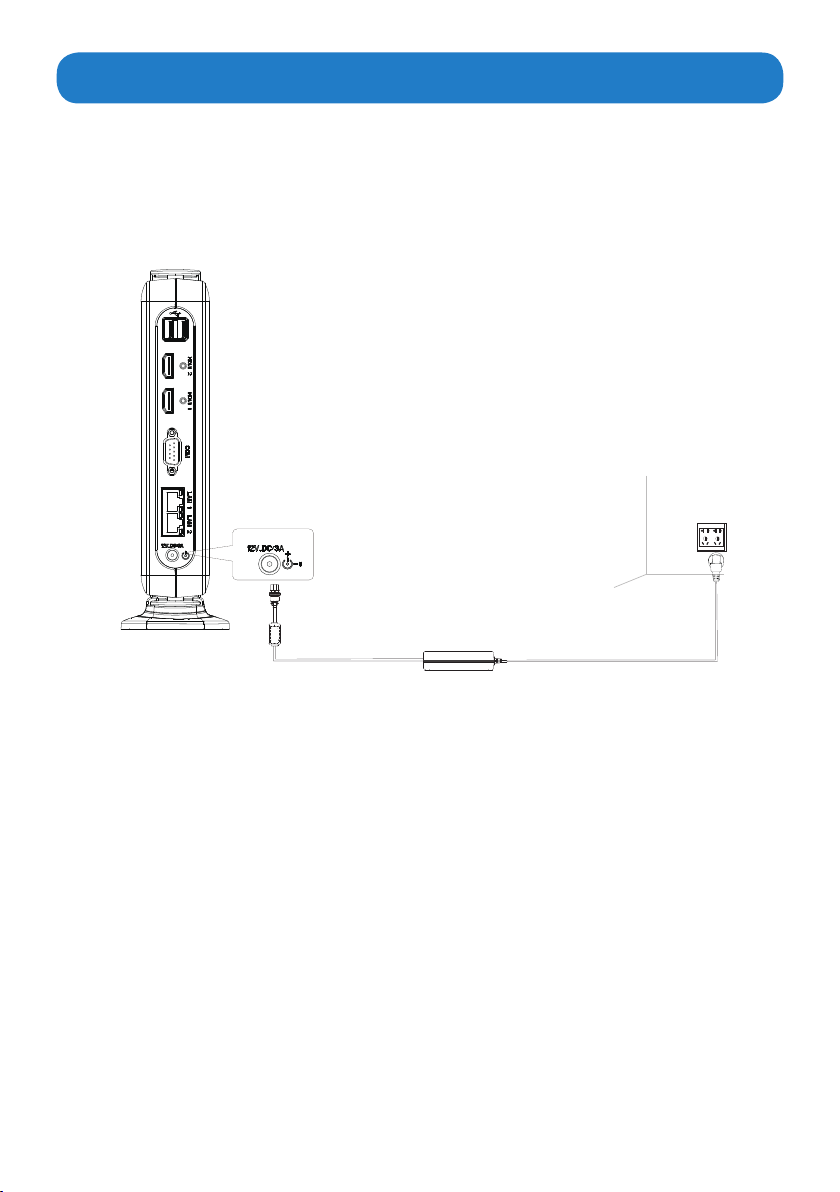
Connecting the power supply
Follow the steps below to connect the power supply.
• Connect one end of the 12V AC/DC power adapter to the DC-in(12V) power connector
of the AP-3500-E01 Office Thin Client. Connect the other end of 12V AC/DC power
adapter to an AC outlet.
AP-3500-E01
DC power connector
AC outlet
17
Page 18
Installing memory module/expansion card
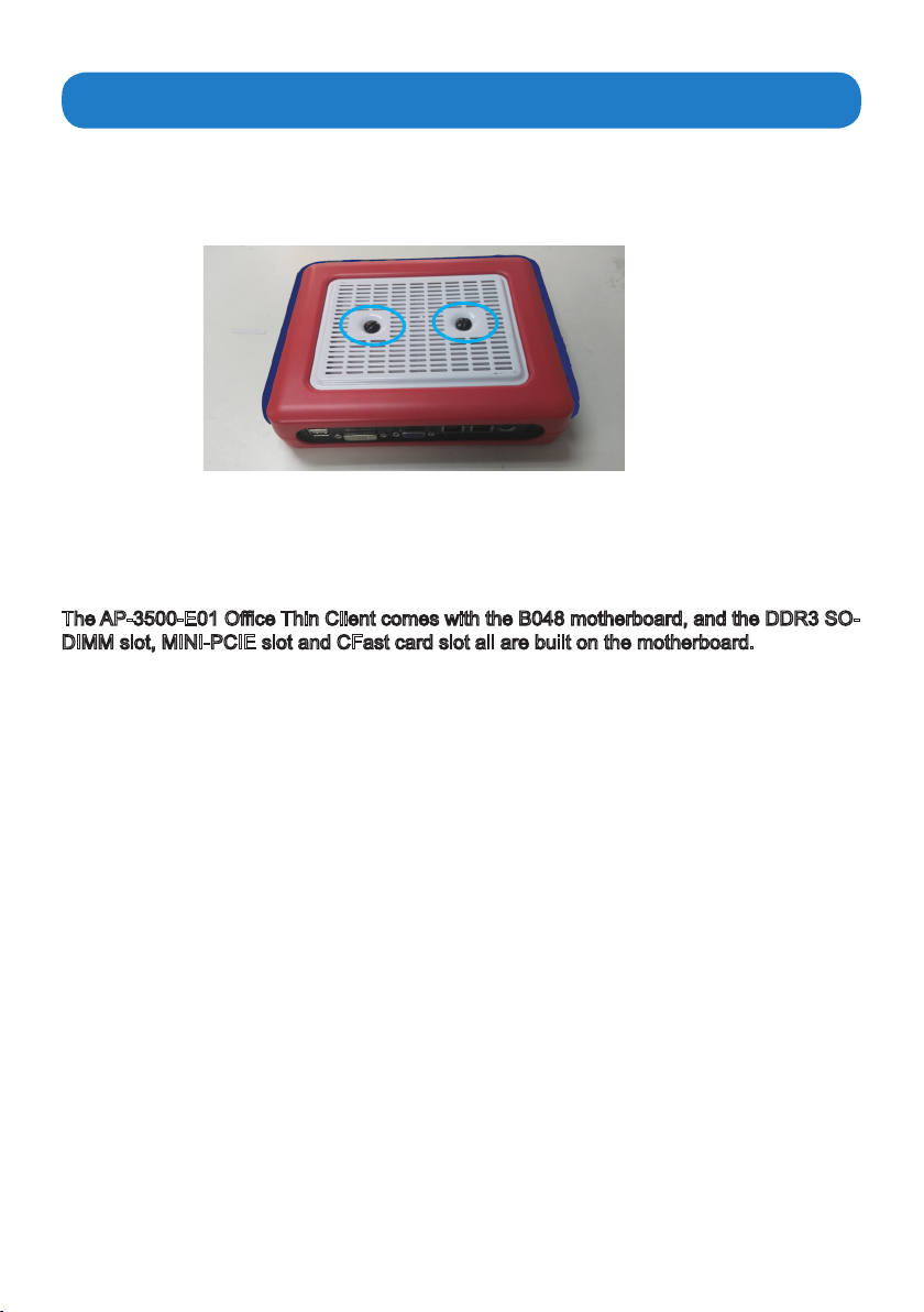
Before you install the memory module or expansion card, please follow the instructions
below to open the bottom cover of theAP-3500-E01OceThinClient.
1. Asshowninthegurebelow,remove the two screws at the center of the bottom cover.
2. Then remove the bottom cover of the AP-3500-E01 Office Thin Client and a metal
protectionbase,youwill nd the DDR3SO-DIMMslot, MINI_PCIE slot andCFastcard
slot on the motherboard.
TheAP-3500-E01OceThinClientcomeswiththeB048motherboard,andtheDDR3SO-
DIMM slot, MINI-PCIE slot and CFast card slot all are built on the motherboard.
Installing the DIMM
The B048 motherboard provides one SO-DIMM slot for DDR3 1333MHz SDRAM memory
modules and supports memory size up to 8GB.
The DIMM1 slot is intended for a memory module.
MB, 512 MB, 1GB, 2GB, 4GB and 8GB DDR DIMM
Note:
Make sure to unplug the power supply before adding or removing DIMM or other
system components. Failure to do so may cause severe damage to both the motherboard
and the components.
You may install 64 MB, 128 MB, 256
into the SO-DIMM slot.
18
Page 19
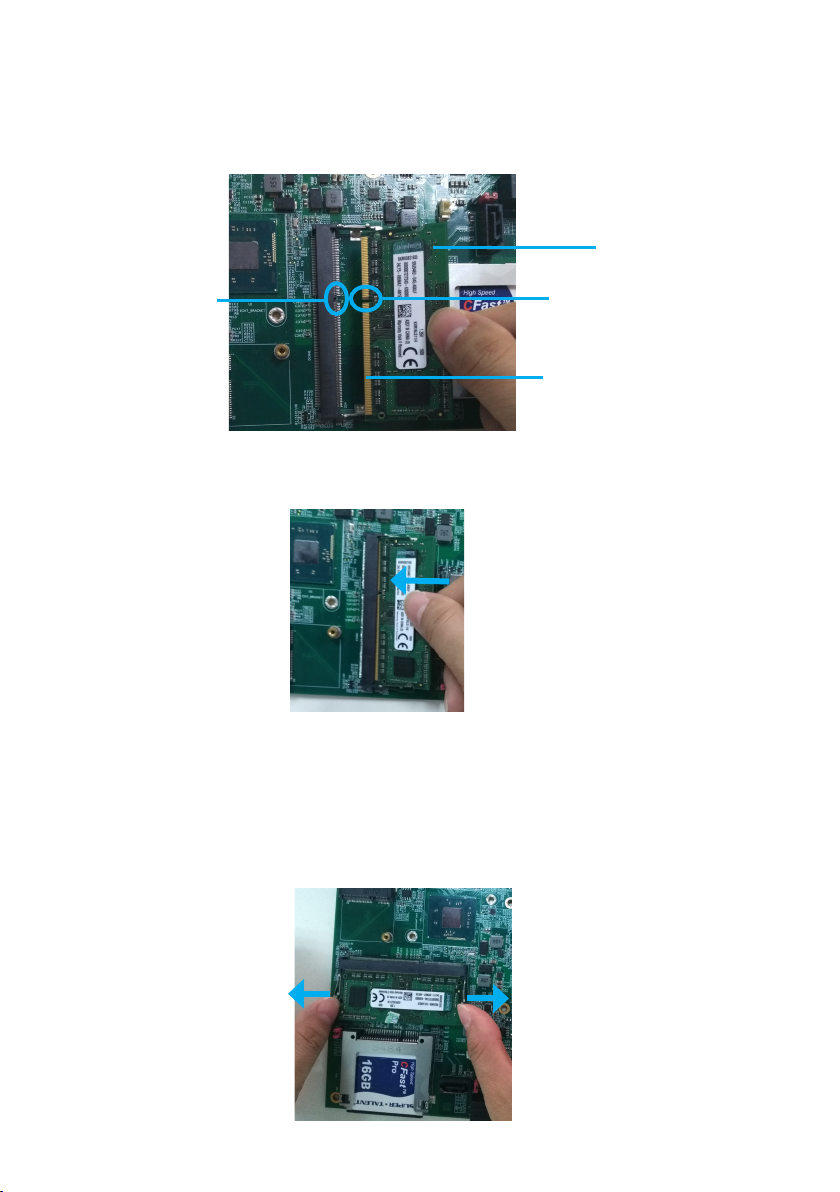
Follow the steps outlined below to install the SO-DIMM.
1. Locate the DIMM on the SO-DIMM slot and align the notch on the DIMM with the key on
the slot.
Note:
DO NOT force a DIMM into a slot to avoid damaging the DIMM.
DIMM
The key on
the slot
2. Insert the DIMM into the slot at 45-degree angle, then pushitinuntilthegoldennger
on the DIMM is deeply inserted into the DIMM slot.
3. Firmly press the DIMM down to lock the module in place.
The notch on
the DIMM
Goldenngeron
the DIMM
Removing the memory module
Follow these steps to remove the DIMM.
1.Useyourngertosimplypushawaytheretainingclipsonbothsidesofthe
slot outward to unlock the DIMM.
DIMM
19
Page 20
2. Then, the retaining clip will release, and gently remove the DIMM from the
Note:
Make sure to unplug the power supply before adding or removing DIMM
system components. Failure to do so may cause severe damage to both
the components.
module.
motherboard and
or other
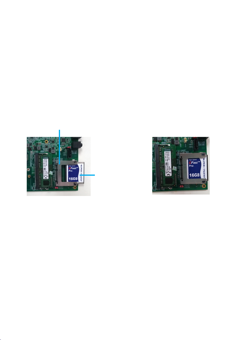
Installing CFast card
Removable memory storage is available on computer with Arista B048 motherboard.
The storage is in the form of a CFast memory card( a compact SATA SSD that comply
with CFast. CFast card slot supports CFast TypeI/II card. Orient the CFast card so that
the notch on the card aligns with the key on the slot(See Figure1 and Figure2).
CFast card slot
CFast card
Figure1
Figure2
20
Page 21

Installing expansion card
The MINI-PCIE slot supports PCIE cards such as a Wi-Fi LAN card, mSATA SSD, SCSI
card,USBcard,andothercardsthatcomplywithPCIEspecications.
Step 1.
switchedoandthepowercordisunplugged.
Please read the documentation of the expansion card and make necessary hardware
settings for the card before you start the installation.
Step 2.
Step 3.
use.
Step 4.
seated on the slot.
Step 5.
Before installing the expansion card, please make sure that the power supply is
Remove the system unit cover (if the motherboard is already installed in a chassis).
Remove the bracket facing the slot that you intend to use. Keep the screws for later
Alignthe cardconnectorwiththeslotand press rmlyuntilthecardis completely
Fasten the card to the chassis with screws.
21
Page 22
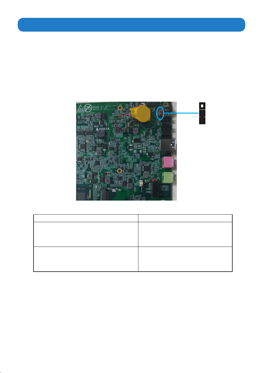
Clearing CMOS data
Asshowninthegurebelow,thisjumperallowsyoutoeraseCMOSdataandresetsetting
to factory default.
Normally this jumper should be set with pins 1-2 closed.
If you want to reset the CMOS data, set the Clear CMOS jumper to 2-3 closed for just a
few seconds, and then move the jumper back to 1-2 closed. This procedure will reset the
CMOS data to its default settings.
Note:
Beforetheoperation,pleasepowerothemotherboardandunplugthepowercord.
3
2
1
Clear CMOS jumper
Description Pin setting
Keep CMOS data(Normal)
Clear CMOS data
Pin1-2 Closed(Default)
Pin2-3 Closed
22
Page 23

Chapter 4 BIOS Setup
Introduction
The computer uses the latest “American Megatrends Inc. ” BIOS with support for Windows
Plug and Play. The CMOS chip on the motherboard contains the ROM setup instructions for
conguringthebuilt-inmotherboardBIOS.
TheBIOS(BasicInputandOutputSystem)SetupUtilitydisplaysthesystem’sconguration
status and provides you with options to set system parameters. The parameters are stored in
battery-backed-upCMOSRAMthatsavesthisinformationwhenthepoweristurnedo.When
thesystemisturnedbackon,thesystemisconguredwiththevaluesyoustoredinCMOS.
TheBIOSSetupUtilityenablesyoutocongure:
• Harddrives,diskettedrivesandperipherals
• Videodisplaytypeanddisplayoptions
• Passwordprotectionfromunauthorizeduse
• PowerManagementfeatures
Thesettingsmadeinthe SetupUtilityaecthowthecomputerperforms. Beforeusingthe
Setup Utility, ensure that you understand the Setup Utility options.
The Standard conguration
AstandardcongurationhasalreadybeensetintheSetupUtility.However,werecommend
that you read this chapter in case you need to make any changes in the future.
This Setup Utility should be used:
• whenchangingthesystemconguration
• whenacongurationerrorisdetectedandyouarepromptedtomakechangesto
the Setup Utility
• whentryingtoresolveIRQconicts
• whenmakingchangestothePowerManagementconguration
• whenchangingthepasswordormakingotherchangestotheSecuritySetup
23
Page 24
Entering the Setup
When you power on the system, BIOS enters the Power-On Self Test (POST) routines.
POST is a series of built-in diagnostics performed by the BIOS. After the POST routines
are completed, the following message appears:
Press the
Resetting the default CMOS values
Whenpoweringonforthersttime,thePOSTscreenmayshowa“CMOSSettingsWrong”
message. This standard message will appear following a clear CMOS data at factory by the
manufacturer. You simply need to Load Default Settings to reset the default CMOS values.
Note:ChangestosystemhardwaresuchasdierentCPU,memories,etc.mayalsotrigger
this message.
Delete key
to access BIOS Setup Utility.
Using BIOS
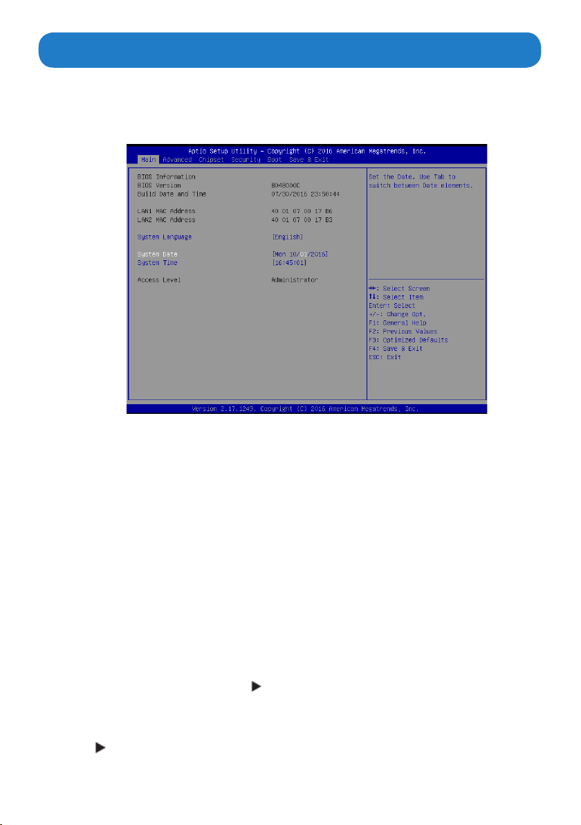
When you start the Setup Utility, the main menu appears. The main menu of the Setup Utility
displays a list of the options that are available. A highlight indicates which option is currently
selected. Use the cursor arrow keys to move the highlight to other options. When an option
is highlighted, execute the option by pressing <Enter>.
Some options lead to pop-up dialog boxes that prompt you to verify that you wish to execute
that option. Other options lead to dialog boxes that prompt you for information.
Some options (marked with a triangle ) lead to submenus that enable you to change the
values for the option. Use the cursor arrow keys to scroll through the items in the submenu.
In this manual, default values are enclosed in parenthesis. Submenu items are denoted by
a triangle .
24
Page 25
The default BIOS setting for this built-in motherboard apply for most conditions
with optimum performance. We do not suggest users change the default values
in the BIOS setup and take no responsibility to any damage caused by changing
the BIOS settings.
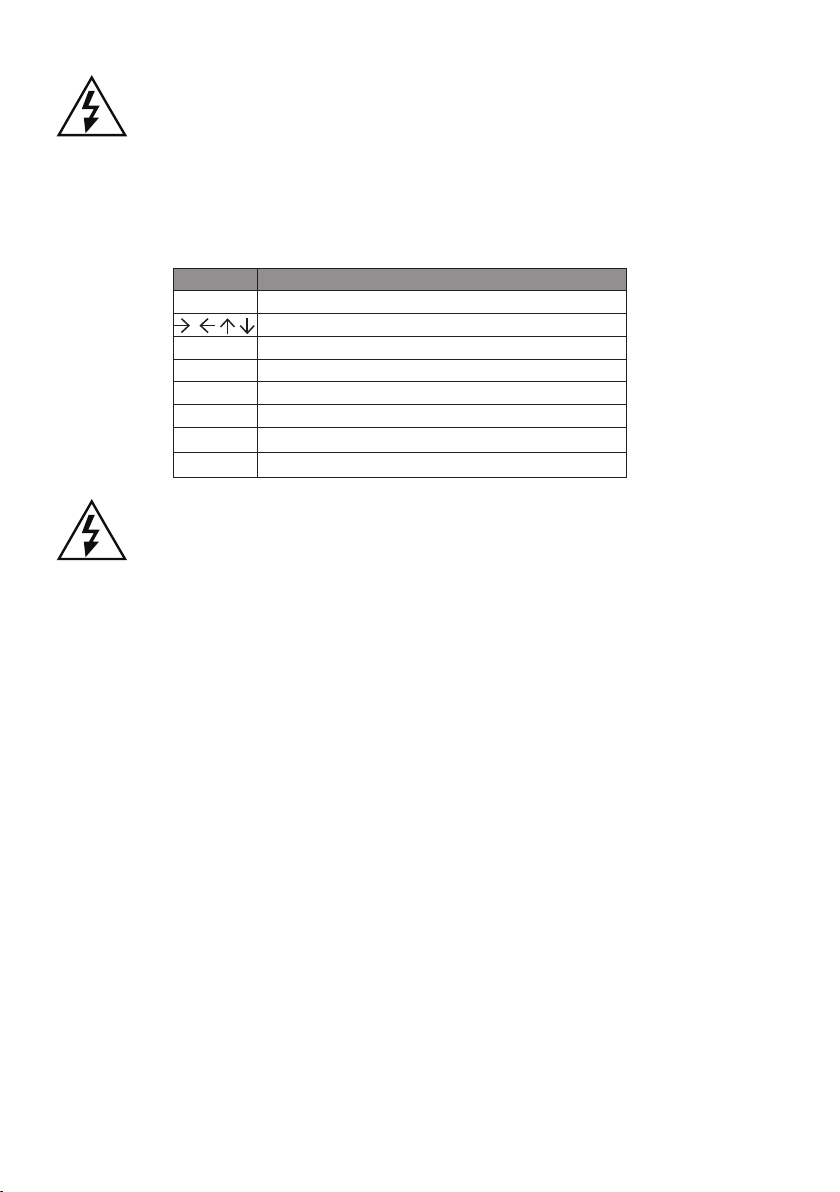
BIOS navigation keys
The BIOS navigation keys are listed below:
KEY FUNCTION
ESC
+/-
Enter
F1
F2
F3
F4
For the purpose of better product maintenance, the manufacture reserves the
right to change the BIOS items presented in this manual. The BIOS setup screens
shown in this chapter are for reference only and may slightly dier from what you
see on your screen. Please visit the manufacture’s website to download the latest
product and BIOS information.
Exits the current menu
Scrolls through the items on a menu
Modiestheselectedeld’svalues
Select
General Help
Previous Value
Optimized Defaults
Save & Exit
25
Page 26
Main Menu
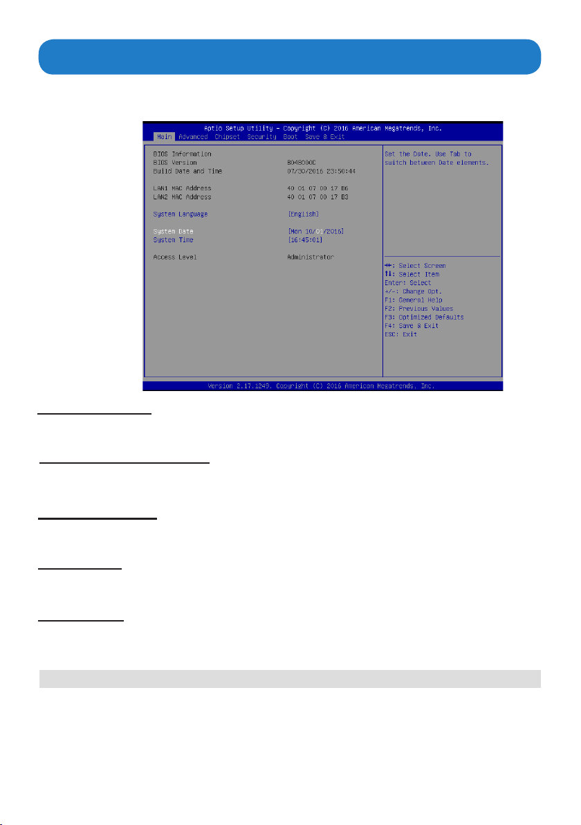
When you enter the BIOS SETUP UTILITY, the Main menu will appear and display the
system overview. You can set the system clock in this main menu.
BIOS Information
This item shows the current BIOS information, including BIOS Version, Build date and time.
LAN1/LAN2 MAC Address
Use this item to view the LAN1/LAN2 Mac address.
System Language
This item allows you to choose the system default language.
System Date
Use this item to specify the system date. Manually enter the day, month and year.
System Time
Use this item to specify the system time. Manually enter the hour, minute and second.
Press <Esc> to return to the Main Menu screen.
26
Page 27
Advanced Menu
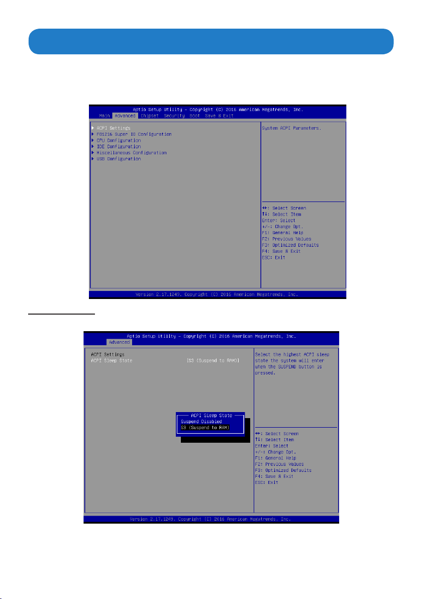
Thissectionallowsyoutocongureandimproveyoursystemandallowsyoutosetupsome
system features according to your preference.
Important:
items.Incorrecteldvaluescancausethesystemtomalfunction.
ACPI Settings
Scroll to this item and press <Enter> to view the following screen:
The default value Be cautious when changing the setting of the Advanced menu
ACPI Sleep State [S3 (Suspend to RAM)]
Select the highest ACPI sleep state, the system will resume when the SUSPEND button is
pressed.
27
Page 28
FB1216 Super IO Conguration
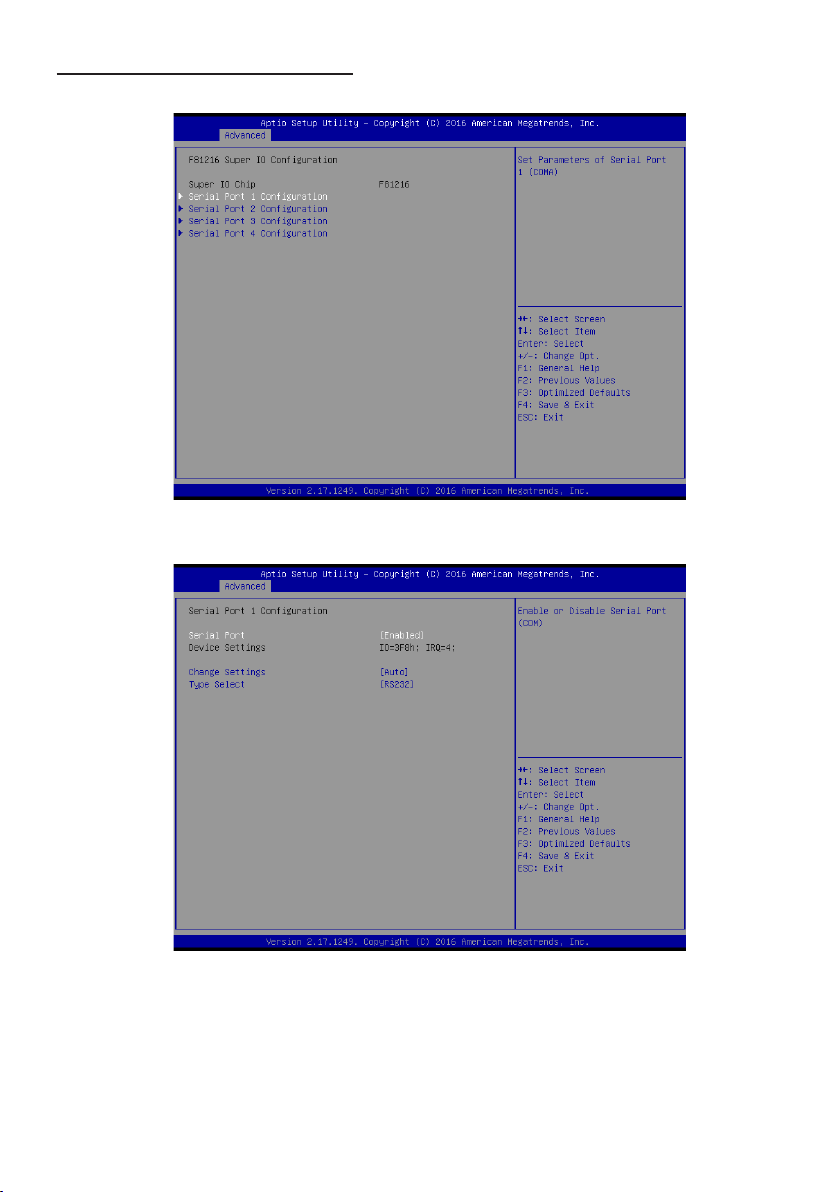
Scroll to this item and press <Enter> to view the following screen:
Serial Port1/Port2/Port3/Port4 Conguration
Serial port1/port2/port3/port4(Enabled)
Use this option to enable or disable the use of serial ports.
Change settings(Auto)
Select an optimal settings for Super IO device.
Type select(RS232)
Select serial port type(RS232,RS422,RS485).
28
Page 29
CPU Conguration
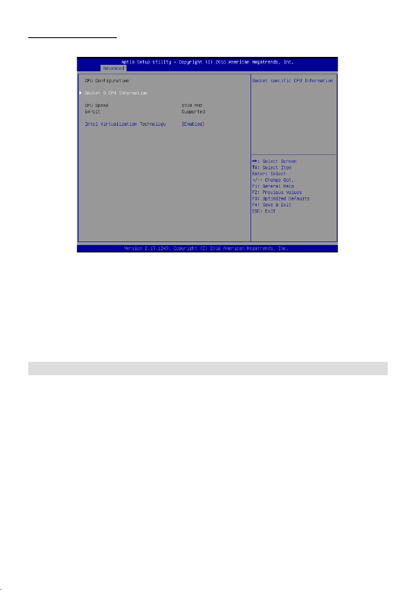
Scroll to this item and press <Enter> to view the following screen:
Socket 0 CPU information
Use this item to view Socket 0 CPU information.
Intel Virtualization Technology(Enabled)
Most of the time, hardware virtualization technology extensions should be enabled in motherboard
BIOS in order to run recent OS and applications. When enabled, a VMM can utilize
the additional hardware capabilities provided by Vanderpool Technology.
Press <Esc> to return to the Advanced Menu screen.
29
Page 30
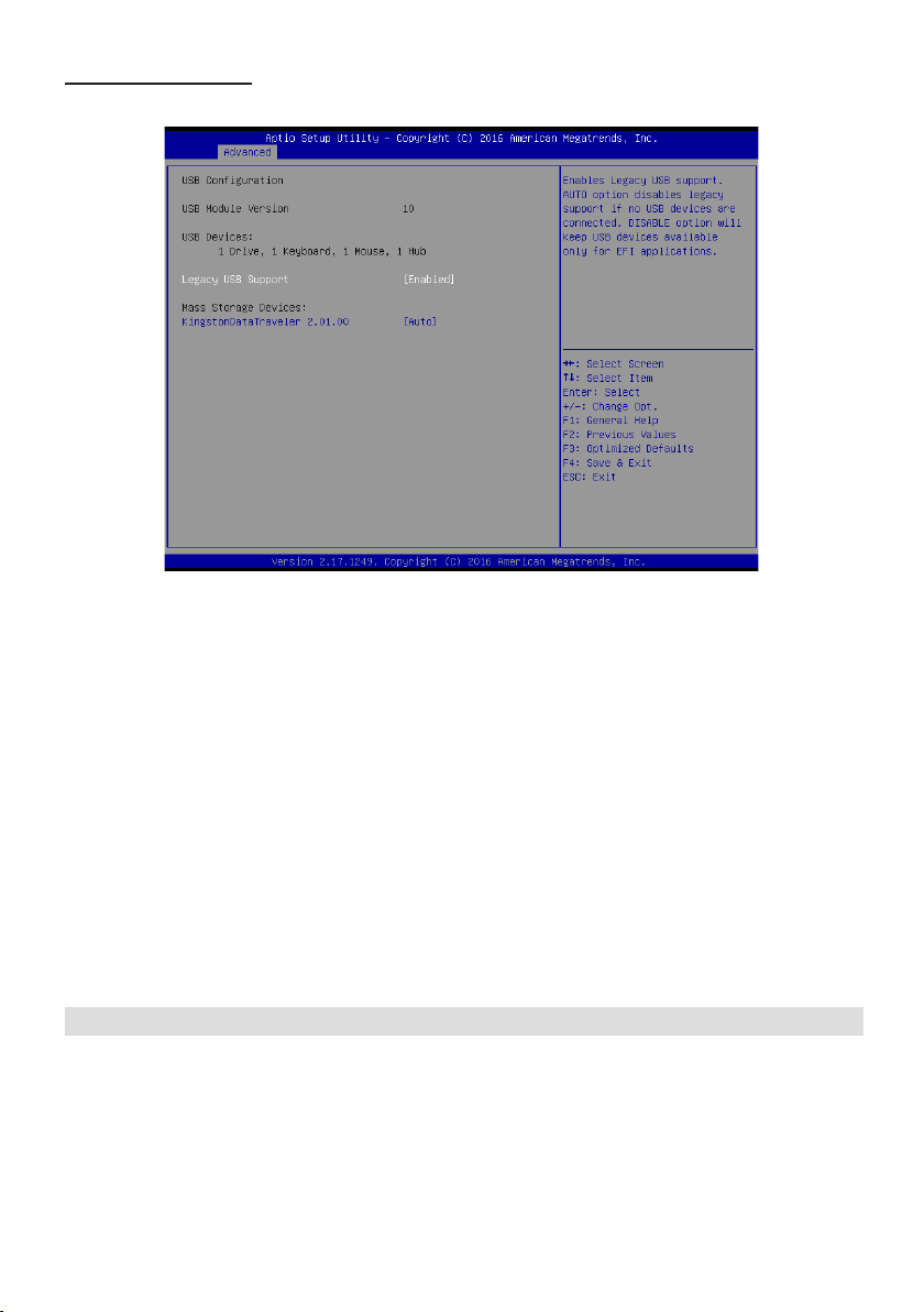
IDE Conguration
Scroll to this item and press <Enter> to view the following screen:
SATA Port1~2 dynamically detect whether there are SATA devices on motherboard. If
devices are connected with the corresponding ports, then it will display the SATA device
type. Otherwise, it will display “Not Present”.
SATA Controllers (Enabled)
Use this option to enable or disable the use of SATA devices.
SATA Mode (AHCI mode)
UsethisoptiontocongureSATAdevicesasnormalIDEdevices.TheoptionsareIDEandAHCI.
SATA Port 0 (Enabled)
Use this item to enable or disable onboard IDE controller. The default value is [Enabled].
CFast card(Enabled)
Use this item to enable or disable the use of CFast card. The default value is [Enabled].
Press <Esc> to return to the Advanced Menu screen.
30
Page 31
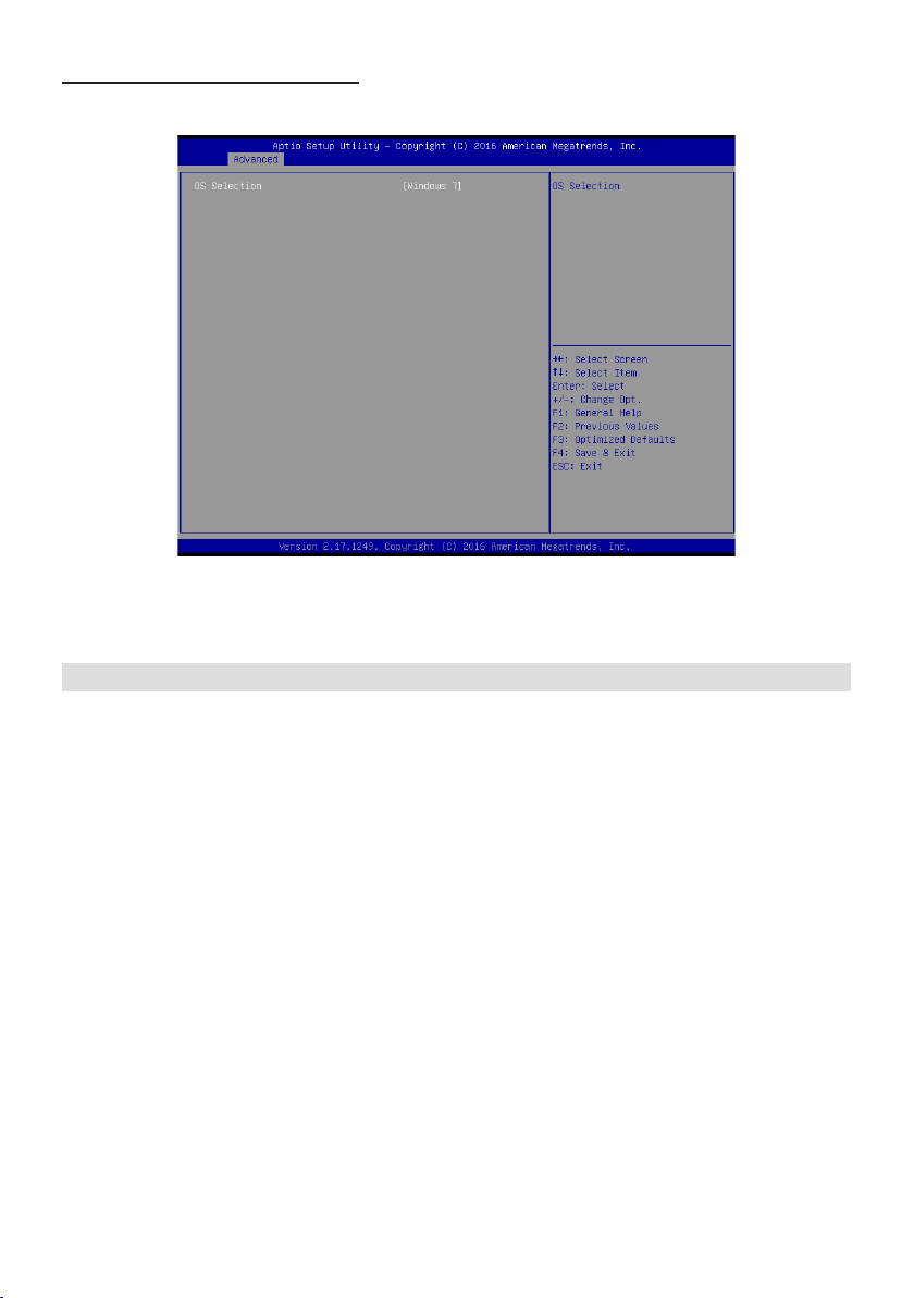
Miscellaneous Conguration
Scroll to this item and press <Enter> to view the following screen:
OS selection (Windows 7)
Use this option to select the operating system for the computer.
Press <Esc> to return to the Advanced Menu screen.
31
Page 32
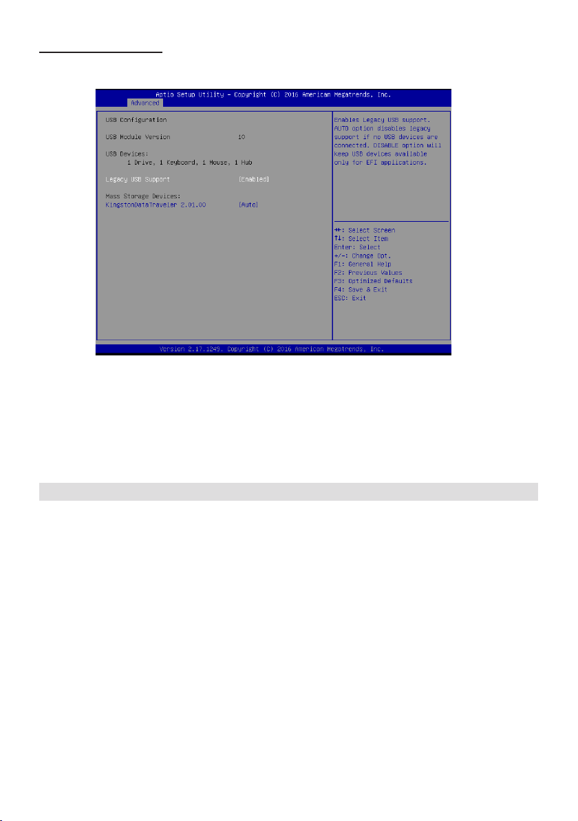
USB Conguration
Scroll to this item and press <Enter> to view the following screen:
Legacy USB Support (Enabled)
Use this option to enable USB mouse and USB keyboard support.
ENABLED option enables legacy USB support.
AUTO option disables legacy support if no USB devices are connected. DISABLED option will
keep USB devices available only for EFI applications.
Press <Esc> to return to the Advanced Menu screen.
32
Page 33
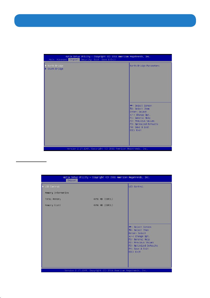
The chipset menu allows you to change the settings for the Host Bridge chipset, South
Bridge, chipset and other system.Since the features in this section are related to the chipset
on the CPU board and are completely optimized, you are not recommended to change the
default settings in this setup table unless you are well oriented with the chipset features.
North Bridge
Scroll to this item and press <Enter> to view the following screen:
Chipset Menu
33
Page 34
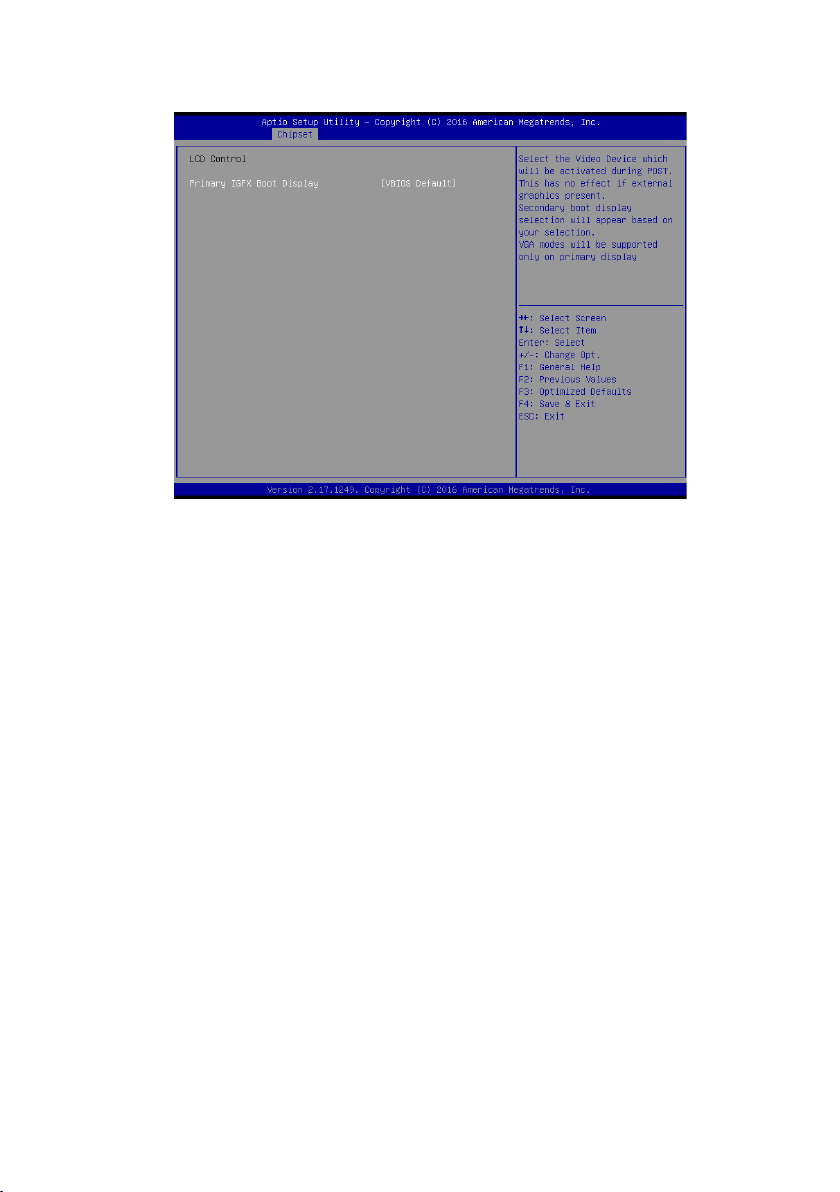
LCD Control
Scroll to this item and press <Enter> to view the following screen:
Primary IGFx Boot display (VBIOS Default)
SelectthevideodevicewhichwillbeactivatedduringPOST.Thishasnoeectifexternalgraphicspresent.
Secondary boot display selection will appear based on your selection. VGA modes will be supported only
on primary display.
34
Page 35
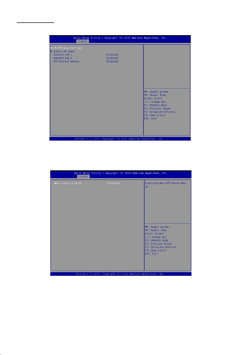
South Bridge
Scroll to this item and press <Enter> to view the following screen:
S5 RTC Wake Setting
Wake system from S5 (Disabled)
Use this option to enable or disable RTC Alarm Wake Up feature.
35
Page 36
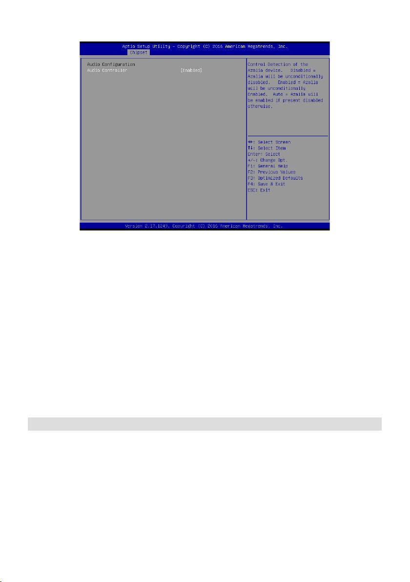
Azalia HD Audio
Audio Controller (Enabled)
Use this option to control detection of the Azalia device.
Azalia controller(Enabled)
Disabled: Azalia will be unconditionally disabled.
Enabled: Azalia will be unconditionally enabled.
Auto: Azalia will enabled if present disabled otherwise.
Onboard LAN1/LAN2(Enabled)
This item allows you to enable or disable the onboard LAN1 or LAN2.
PCI Express Wakeup(Enabled)
This item allows you to enable or disable PCI Express Wakeup feature.
Press <Esc> to return to the Chipset Menu screen.
36
Page 37
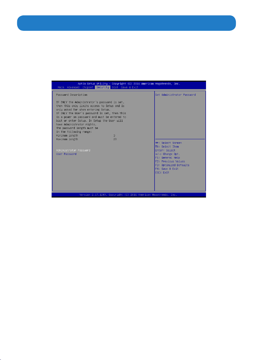
The Security Menu allows you to set Administrator and User password.
If ONLY the Administrator’s password is set, then this only limits access to setup and is
only asked for when entering Setup.
If ONLY the user’s password is set, then this is a power on password and must be entered
to boot or enter Setup. In Setup, user will have administrator rights.
The password length must be in the following range: Minimum length:3, Maximum:20.
Security Menu
37
Page 38
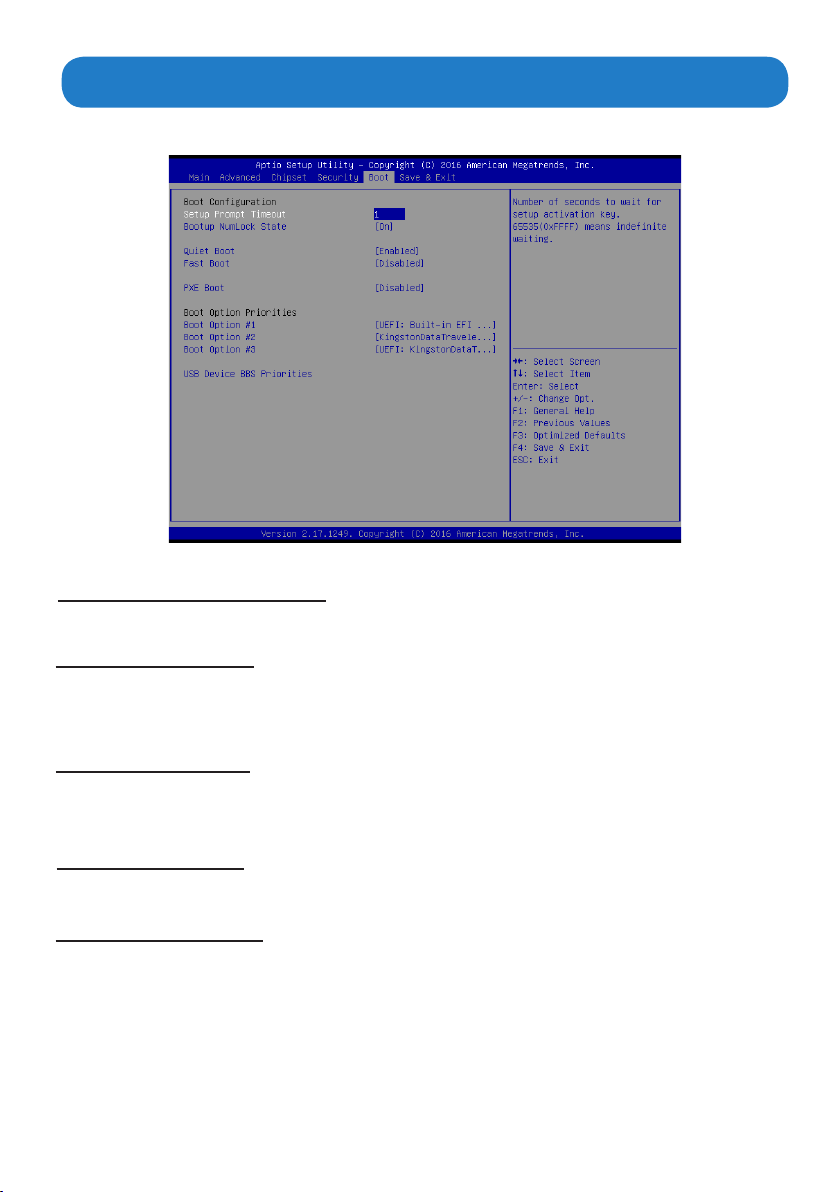
The Boot Menu allows you to change the system boot options.
Bootup Num-lock state (ON)
If this item is set to “On”, it will automatically activate the Numeric Lock funcition after boot-up.
Quiet Boot (Enabled)
ThisitemallowsthebootupscreenoptionstobemodiedbetweenPOSTmessagesorthe
OEM logo.Select “Disabled” to display the POST messages. Select “Enabled” to display
the OEM logo instead of the normal POST messages.
Boot Menu
Fast Boot (Disabled)
This item enables the BIOS to skip certain tests in order to speed up the boot sequence.
This feature has two options: [Enabled] [Disabled].
PXE Boot(Disabled)
This item allows you to control the execution of UEFI and Legacy PXE OpROM.
Boot Option Priorities
This item allows you to select system boot order.
38
Page 39
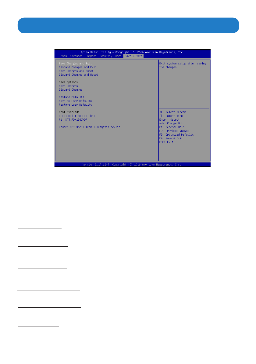
Save & Exit Menu
The Save & Exit Menu allows you to save the changes that you have made in the Setup
Utility and exit
Save Changes and Exit
Whenyou select this option, it will pop-out the following message, “Save conguration
changes and exit setup?” Select [OK] to save the changes and exit the UEFI SETUP UTILITY.
Discard Changes and Exit
When you select this option, it will pop-out the following message, “Discard changes and
exit setup?” Select [OK] to exit the UEFI SETUP UTILITY without saving any changes.
Save Changes
Use this item to save the changes made to the BIOS options and reset the system.
the Setup Utility.
Discard Changes
UsethisitemtoexitthesystemwithoutsavingthechangesmadetotheBIOSconguration
Restore Defaults
This option restores all BIOS settings to the factory default. This option is useful if the
controller exhibits unpredictable behavior due to an incorrect or inappropriate BIOS setting.
Save as user defaults
Use this item to save the settings as user defaults.
Restore User defaults
Use this item to restore user defaults.
Boot Override
This option lists all the booting options; users may choose one of
the options and press <Enter>, then you may boot according to the option.
39
Page 40

Chapter 5 Appendix
Care and
Regular maintenance of the AP-3500-E01OceThin Client can help prevent damage or
downtime.
Serviceshouldonlybeperformed by qualied and authorized personnel.Makesureyour
touch panel computer is powered down and unplugged before removing the cover or
working on internal components.
• Keep the AP-3500-E01OceThinClient in a dry, clean space. Make sure the unit has
minimal exposure to dust - don’t get the power switches or other controls wet.
• If the AP-3500-E01OceThinClient getswet,poweritoimmediately.WaitfortheAP-
3500-E01OceThinClient to dry completely before powering it on again.
• If you move it from a very cold environment to a warm environment, give the
components time to reach room temperature before powering it on.
• Clean the exterior surfaces of the unit with a soft, damp cloth. Never use alcohol, paint
thinner or benzene to clean this unit.
• Occasionaly remove dust from interior surfaces, taking care not to touch or damage
connections or chips.
• Position your system unit away from direct sunlight, moisture, dust, oil and thoroughfare.
• Never expose the unit to harsh jarring.
• Ensure that all ventilation outlets are always free from obstruction.
• To protect components against damage from static electric discharge, you should:
Use a grounding wrist strap. The strap will have an “alligator”clip at the end of a
shielded wire lead. Clip it to a grounded object. Put on and connect the strap before you
handle the components. Also, you can use an anti-static pad. Put any components on
the pad whenever you work on them outside the computer. If you don’t have a pad, put
the components on the anti-static bag them came in.
Maintenance
• Back up all the critical data,in a situation of unit being moved there are chances of hard
diskgettingdamaged Before moving,remove all datadisksfrom the drive,turn o the
computer and all the peripherals. Also unplug the power and disconnect cables.
• In the event of mechanical/power failure or damage, do not attempt to repair the system
unit or wires. Refer all such problems to experienced personnel.
• If the unit needs servicing, please consult the authorized dealer through the contact
information provided on the warranty card. Faulty service may void the warranty.
40
Page 41

Product Limited Warranty
Arista AP-3500-E01 sold in the U.S.A and Canada comes with two-year warranty. Arista
warran-ty obligations for its products are limited to the terms&conditions listed below.
1. Limited Warranty Coverage
• If the purchased product does not work due to defect in materials, starting after three
years from the date of purchase (invoice date),Arista Corporation will repair or replace
with new or refurbished product or parts.
• Arista Corporation holds every right to decide for repair or replacement of any product
or part. During the “labor” limited warranty period there will be no charge for labor and
during the “parts” limited warranty, there will be no charge for parts.
• Customers should ship the defective product or parts to Arista Corporation at their
expense. After repair or replacement, Arista will pay for shipping via UPS Ground back
to the customer.
• This limited warranty applies to products and services only in the North America region.
Arista Corporation will not pay for any shipping for product or parts for any location
outside of United States.
2. Exclusions and Limitations
• Limited warranty is applicable to defect in material or workmanship, it does not cover
any general wear and tear, or cosmetic damaged.
• Damage due to external causes, including, but not limited to, failures which are caused
by products not supplied by Arista Corporation. Also adding or altering any component
without any prior concurrence from Arista Corporation technical support.
• Limited warranty does not apply to damages caused by failure or negligence, this
include accidents, misuse, abuse, mishandling, misapplication, alteration, faulty
installation, set-up adjustment, improper maintenance, power surge issues with
electrical stability, failure to maintain environmental conditions specified by the
manufacturer, wrong attempt to relocate the system, lightning damage, modification,
product servicing from unauthorized providers, inappropriate product usage without
referring to the manual or instructions and any other change in product component
without prior guidance from Arista Corporation technical support.
• Any sighs of tempering/altering with serial number will void this warranty.
• There is no expressed warranty except as stated under “Limited Warranty Cov-erage”.
Under no equitable theory shall Arista Corporation be held liable for monetary and/or
non-monetary damage resulting from normal or abnormal usage of our products. Use,
distribution and/or similar engagement of our products constitute implied agreement to
these and similar Arista Corporation limited liability policies.
3. Technical Support
• Arista Corporation entire team is dedicated towards customers’ needs and re-
quirements. Arista’s technical support team is available to resolve customer is-sues over
phone and email. If required, an RMA number is issued to resolve any sort of problem
faced by customers.
• Customers are required to keep the product serial number handy when contact-ing the
technical support.
• Arista Corporation technical support can be reached at Monday through Friday 8:00am
to 5:00PM PST at 510-226-1800 ext.400,Fax 510-226-1890 or email support@goarista.
com.
41
Page 42

4. RMA (Return Material Authorization) Procedures
• All return requests are provided with a number, please contact Arista customer service
or complete RMA request form to obtain a number before returning any products or
parts.
• Returns will be authorized in accordance with the following policy: If it is deemed that
the unit/part should be returned, Arista’s customer service representative will give the
customer a return authorization number and ship to address to return the product.
• Products will not be accepted by Arista Corporation’s RMA department for return if not
accompanied by a valid RMA number, which must be clearly marked on the outside of
the package.
• Products must be returned within 30 days after the date of when RMA number was
issued. After the 30-day period, the RMA number issued will be invalid. Please do
not return products with an invalid RMA number; contact Arista’s cus-tomer service
representative if your RMA number is invalid. Customer service can be reached at
Monday through Friday 8:00am to 5:00PM PST at 510-226-1800 ext.400,Fax 510-226-
1890 or email [email protected].
Warranty Returns
• All returning products should be returned within the applicable warranty period. After
warranty period is over, the original product will be returned to the customer.
• The RMA number for Warranty Return will be issued within 24 hours from the time the
RMA application form is received by Arista.
Non-Warranty Returns
• If the customer wishes to return a product for repair that is no longer within the
warranty period, or any kind of damage not covered by the warranty, an Arista sales
representative will inform the customer of the estimated cost of the repair.
• Return of the product will be counted as the authorization to repair and agreement to
pay for the cost of repair, whether or not it exceeds the original estimate.
5. RMA Credit Policy
Returns for Credit & Credit Types
Returns for credit that require Arista’s management approval may take up to 48 hours for
processing/approval. Products can be returned for credit with the following condi-tions:
• Dead on Arrival (DOA): The customer must report DOA units to Arista’s RMA department
in 14 calendar days after the product is received. Customer can re-quest either return
for credit or replacement. If replacement is requested, Arista will ship the replacement
in 7 calendar days and invoice the customer for the re-placement. A credit memo will be
issuedtothecustomeraftertheDOAproductisreceivedandveried.
• Evaluation Return: The customer must notify Arista’s RMA department before or at the
end of the evaluation period if the customer decides to return the evalu-ation unit. An
RMA number must be obtained from Arista prior to returning the unit.
• Short Shipment: The customer must report for any item received short-shipped or
wrong products received in 7 calendar days after the product is received. The customer
can request either: shipment of missing items, replacement of wrong items or return
for credit. If shipment of missing items or replacement of wrong items is requested,
Arista will ship the replacement in 7 calendar days. A credit memo will be issued to the
customerafterthereturnedproductisreceivedandveried.
• Non-Open-Box Return: In the event where a customer places an incorrect order, over
stock or double orders, the customer can request return for credit with the following
restocking fees applied.
42
Page 43

• Restocking Fee: A 15% restocking fee will apply to non-open-box returns when returned
within 3 months after invoice date. A 30% restocking fee will apply to non-open-box
returns returned within 6 months. Beyond 6 months after invoice date, a 50% restocking
fee will apply to non-open-box returns returned within 12 months. Beyond 12 months
after invoice date, Arista will not grant authorization to return non-open-box returns for
credit.
• Return Condition: All valid returns for credit products must be returned in its original
packaging and in good condition along with all the items and accessories originally
shipped with the product. Any damages will be assessed and the cost of repair or
refurbishment will be deducted from the credit issued.
• No Credit DOA: No credit will be given to the customer for DOA products re-ceived by
Arista beyond 30 calendar days after the invoice date. No credit will be given to all noncancellable, non-returnable, custom order parts.
6. RMA Transportation Policy
Transportation Charges
• All customers are responsible for all freight charges involved in shipping defec-tive
products back to Arista Corporation.
• Arista Corporation will cover the cost of returning products that are under warranty via
UPS Ground to customers in the United States after repair or replacement.
• International customers are responsible for all transportation, insurance, duties and
other similar charges for all returned products shipped outside of the United States and
must ensure that the product is appropriately packaged.
• Shipping damages resulting from improper packaging will be the customer’s re-
sponsibility.
• Arista is not responsible for products lost during shipment. All products being re-turned
for Limited Warranty repair or replacement must be sent freight prepaid.
Transportation Damages
• In casesoftransportationdamage,thecustomer isresponsibleforlingall claims with
the shipping carrier.
• To avoid any potential risk that an RMA product is lost or damaged while in tran-sit to
Arista, it is recommended that the customer insures and declares the full value of the
RMA product. The customer is 100% responsible for the RMA prod-uct while in transit to
Arista.
• We urge customers to pack the RMA product carefully to avoid transit damage.
Refused Shipment Restocking Fees
• If a customer refuses a shipment, credit will be issued only after the refused product is
receivedandveriedbyArista.The shippingchargeplus 15% restocking feeswillbe
billed to the customer.
43
Page 44

7. RMA Transportation Policy
Product Non-Acceptance
• Products will not be accepted by Arista Corporation if not accompanied by a valid RMA
number, which must be clearly marked on the outside of the package.
• Any products refused by Arista will incur the fees and/or charges applied by the shipping
carrier, and shall be the sole liability of the original shipper.
Sample RMA Shipping Label
ARISTA CORPORATION
Attention: RMA Department
40675 Encyclopedia Circle
Fremont, CA 94538
RMA: # _______________
Package Identication
• Each boxmustreference the following information:Customer/Contact Name • Return
Address•PhoneNumber•RMANumber(issuedbyanautho-rizedARISTAsource).
• The RMA number must be written on the outside of the shipping container for
identicationpurposes.
• Shipmentsnotproperlyidentiedwillberefused.
• To avoid any discrepancy of items received, please do not return accessories (manuals,
driver CDs, OS CDs, cables, etc.) with the RMA unit in need of repair.
• If available, use the original box/packaging to ship back RMA units to avoid tran-sit
damage.
RMA Rejection Policy
Arista reserves the rights to return any RMA product received that does not comply with the
information given on the original Return Material Authorization (RMA) request, such as:
• Invalid RMA number
• RMA number not visible and/or not on the box shipping label
• RMAconditiondescribedbythecustomerdiersfromtheactualconditionoftheproduct
• Expired RMA number
• Unauthorized return (no RMA # was issued)
• No Arista serial number on the product
• Product is physically damaged
• If you have any questions regarding Arista’s RMA procedures, product return policies
and/or other similar issues, please call Arista’s Customer Service and RMA Department
duringocehours,MondaythroughFriday(8:30am-5:30pmPST)
• Phone: (510) 226-1800 ext. 400
• Fax: (510) 226-1890
• Email: [email protected]
44
Page 45

8. Arista’s Limited Liability
Product Non-Acceptance
• Arista Corporation is not liable for incidental or consequential damages resulting from
the use of Arista products or arising out of any breach of Arista’s full limited warranty.
• Under no equitable theory shall Arista Corporation be held liable for mone-tary and/
or non-monetary damages resulting from the normal or abnormal usage of our
products. Use, distribution and/or similar engagement of our products constitute implied
agreement to these and similar Arista Corporation Limited Liability policies.
• Arista Corporation is not liable for damages or reimbursement for lost time, lost revenue,
and cost of having someone remove or re-install an installed unit if applicable, or travel
to and from the service providers.
• All expressed and implied warranties, including the limited warranty of Mer-chantability
are limited to the period of the limited warranty, unless, otherwise, indicated in writing by
Arista Corporation.
9. Customer Responsibilities
• By requesting service, the eligible customer acknowledges the terms of the limited
warranty, including the disclaimer and limitation of liability provision.
• Priortoseekingservice,customersmustback-upalldata,programs,lesand/orsimilar
digital documents that may become damaged and/or lost due to service.
• Arista Corporation, WITHOUT LIMITATION, is not responsible for lost, dam-aged or
otherwise destroyed data due to service.
45
Page 46

Disposal and Recycling Information
AP-3500-E01 Office Thin Client must be disposed as per the local laws and
regulations applicable to that location. Once the product reaches end of its life cycle
and needs to be disposed, local authorities should be contacted for appropriate
options.
This symbol on the product or in the manual means that electrical or
electric equipment should be disposed at the end of its life-cycle separately and
not in the regular household waste. There are separate collection systems for
recycling in the EU. For more information, please contact your local authorities or
your retailer where you purchased the product.
Disclaimer and Copyright Notice
Disclaimer
Alltheinformation, design and specicationscontained in this manualwere correct
publication.However,astheproductgoesundercontinuousupgradesandchanges,thenal
device may have slight differences. The contents of this manual are subject to changes
without prior notice, and Arista Corporation shall not be liable for any
or for incide or consequential damages in connection with the furnishing, performance, or
use of this manual.
errors contained herein
contained in this manual were correct in this
© Copyright 2014
The information contained in this user’s manual and all accompanying documentation
is copyrighted and all rights are reserved. This publication may not, in whole or in part,
be reproduced, transcribed, stored in a retrieval system, translated into any language or
computer language, or transmitted in any form whatsoever without the prior written consent
from the manufacturer, except for copies retained by the purchasers for their personal
archival purposes. The manufacturer reserves the right to revise this user’s manual and
all accompanying documentation and to make changes in the content without obligation to
notify any person or organization of the revision or change.
IN NO EVENT WILL THE VENDOR BE LIABLE FOR DIRECT, INDIRECT, SPECIAL,
INCIDENTAL,ORCONSEQUENTIALDAMAGESARISING OUT OF THE USE OR
INABILITY TO USE THIS PRODUCT OR DOCUMENTATION; EVEN IF ADVISED OF
THE POSSIBILITY OF SUCH DAMAGES. IN PARTICULAR, THE VENDOR SHALL NOT
HAVE LIABILITY FOR ANY HARDWARE, SOFTWARE, OR DATA STORED OR USED
WITH THE PRODUCT, INCLUDING THE COSTS OF REPAIRING, REPLACING,OR
RECOVERING SUCH HARDWARE, SOFTWARE, OR DATA.
Alltrademarksmentioned in this documentareacknowledged.The specications in this
manual are subject to change without notice.
in this
46
Page 47

Talk to us. We listen.
TM
Arista Corporation
40675 Encyclopedia Circle, Fremont, CA 94538 U.S.A.
Tel: (510) 226-1800 Fax: (510) 226-1890
http://www.goarista.com
 Loading...