

Page 1

NK12X 1U
USER MANUAL
Arima Computer Corp.
Building Your Competitive Advantage
1
Page 2

T
ABLE OF CONTENTS
:
LEGAL DISCLAIMER.................................................................................................... 3
COPYRIGHT NOTICE................................................................................................... 3
TECHNICAL SUPPORT................................................................................................. 4
ABOUT THIS USER GUIDE.......................................................................................... 4
SAFETY INSTRUCTION................................................................................................ 5
CHAPTER 1. GETTING STARTED ............................................................................ 6
1.1 C
ONGRATULATIONS
1.2 U
NPACKING
1.2.1 MB Quick Installation Guide............................................................................................................ 7
1.2.2 NK1231U Quick Installation Guide.................................................................................................. 8
1.3 S
YSTEM SPECIFICATION
1.4 S
ERVERBOARD SPECIFICATION
1.5 S
ERVERBOARD LAYOUT [MAJOR COMPONENTS
........................................................................................................................................ 6
........................................................................................................................... 6
..................................................................................................................... 9
........................................................................................................ 10
] ........................................................................... 12
CHAPTER 2. HARDWARE INSTALLATION......................................................... 13
2.1 S
YSTEM INSTALLATION
2.2 B
LOCK DIAGRAM
2.3 J
UMPER CONFIGURATION
2.3.1 Clear CMOS header........................................................................................................................ 23
2.3.2 Enable onboard VGA header.......................................................................................................... 24
2.3.3 Onboard Buzzer .............................................................................................................................. 25
2.3.4 Mouse Header ................................................................................................................................. 26
2.3.5 Intrusion Function Pin Header......................................................................................................... 27
2.3.6 Flash Recovery Pin Header.............................................................................................................. 28
2.3.7 IPMI Header .................................................................................................................................... 29
2.3.8 LPC Connector Header.................................................................................................................... 30
2.4 P
OWER SUPPLY
2.4.1 ATX 24-pin power connector and CPU 8/4-pin connector.............................................................. 31
2.5 C
ABLES
& C
2.5.1 Front Panel Connectors.................................................................................................................... 33
2.5.2 IDE connectors................................................................................................................................ 35
2.5.3 Rear Panel I/O ports........................................................................................................................ 36
2.5.4 Back Panel LAN LED .................................................................................................................... 37
2.5.5 Front USB Connector ..................................................................................................................... 38
2.5.6 Front Panel Serial Port Connector................................................................................................... 39
................................................................................................................................. 31
ONNECTORS
.................................................................................................................... 13
.............................................................................................................................. 22
............................................................................................................... 23
.................................................................................................................. 33
CHAPTER 3. BIOS SETUP ......................................................................................... 40
3.1 E
NTERING
3.2 U
SING SETUP
3.3 T
ROUBLESHOOTING
3.4 M
AIN MENU
3.5 A
DVANCED MENU
3.5.1 Hammer Configuration Sub-Menu .................................................................................................. 45
3.5.2 Integrated Devices Sub-Menu.......................................................................................................... 46
3.5.3 IDE Configuration Sub-Menu.......................................................................................................... 48
3.5.4 I/O Device Configuration Sub-Menu............................................................................................... 50
3.5.5 Console Redirection Sub-Menu....................................................................................................... 51
3.6 S
ECURITY MENU
3.7 P
OWER MENU
3.8 B
OOT MENU
3.9 S
ERVER MENU
3.10 E
XIT MENU
3.11 BIOS FLASH UPGRADE UTILITY........................................................................................... 57
BIOS S
ETUP
.................................................................................................................... 40
..................................................................................................................................... 41
.......................................................................................................................... 42
...................................................................................................................................... 43
............................................................................................................................. 44
............................................................................................................................... 52
................................................................................................................................... 53
...................................................................................................................................... 54
................................................................................................................................... 55
...................................................................................................................................... 56
APPENDIX I: GLOSSARY........................................................................................... 58
2
Page 3

Legal Disclaimer
The information provided in this document is subject to change without notice.
Arima Computer Corp. makes no warranty regarding this document.
Always read the safety instructions carefully.
Arima Computer Corp. cannot anticipate all of your working conditions; for safety, you should use caution,
care and good judgment when following the procedures described in this material. Arima Computer Corp.
shall not be liable for errors contained in this material nor any damage incurred in the use of this material.
Arima Computer Corp. assumes no responsibility for any damage to property, injury to persons, or losses
incurred as a result of misuse of the information provided.
Arima Computer Corp. assumes no responsibility for the reliability of its software on equipments that are
not manufactured by Arima Computer Corp.
Copyright Notice
This document contains proprietary information that is protected by copyright. All rights are reserved. No
part of this publication may be reproduced, transcribed, stored in a retrieval system, translated into any
language or computer language, or transmitted in any form whatsoever without the prior written consent of
Arima Computer Corp.. We reserve the right to make changes to this document without notice.
Copyright 2007 by Arima Computer Corp.. All rights reserved.
Other products and companies referred to herein are the trademarks or registered trademarks of their
respective companies or mark-holders.
Opteron™ is registered trademark of AMD Corporation.
Windows® 98/2000/NT/XP are registered trademarks of Microsoft Corporation.
ATI is the registered trademark of ATI Technologies Inc.
Revision: 1.00
Release Date: Aug 2007
3
Page 4
Technical Support
If a problem arises with your system during installation or operation and is unable to be resolved from the
user manual, consult the following list of resources for help:
Contact the place of purchase for help. This is the recommended solution as they can provide the
quickest assistance.
Visit Arima Computer Corp. website for up to the minute FAQ, guides and updates. The website can
be found at: http://www.arima.com.tw/server
Or contact our support staff at: [email protected]
About this User Guide
This manual contains some special icons that accompany special sections that are meant to help you along
in the installation process. The special sections contain useful and/or critical information that you should
know. Watch for these icons as you read through the manual.
Type of icons: Description:
NOTE
WARNING
This icon indicates useful and timely information
that will aid you in the setup.
This icon indicates information on dangerous
and/or costly behavior to avoid.
4
Page 5

Safety Instruction
Keep this manual for future reference.
Keep the equipments in a safe, cool, dry place.
Perform the installation on a dry, flat surface.
Ground yourself by touching a plugged-in power supply, which displaces static electricity.
Adjust the power source to the proper voltage before connecting the equipment to the power outlet.
Place the power cord in such a manner as to ensure that no one can step on it or trip over it.
Always unplug the power cord when performing installation.
Do not have liquid nearby as electrical shock can occur if liquid spills onto the equipment.
Operating temperature: 10ºC to 35ºC or 50ºF to 95ºF.
Pay attention to the warnings in the installation instructions when appropriate.
In the following cases, do not try to fix the problem yourself, contact a party in Technical Support
The power cord or plug is damaged.
Liquid has been spilled onto the equipment.
Obvious sign of damage can be detected on the equipment.
Danger of explosion if battery is incorrectly replaced. Replace only with
the same or equivalent type recommended by the manufacturer.
Dispose of used batteries according to the manufacturer’s instructions.
5
Page 6

Chapter 1. Getting Started
1.1 Congratulations
You have in possession one of the most powerful and versatile 1-way AMD Opteron processor solutions,
the NK12X 1U. It well designedly forms 2 nodes in 1U system that can save you chassis, power supply,
and rack cost. It also delivers higher power utilization, reduces maintenance/management costs, and fits the
customer’s requirements for HPC computing cluster; data center; search engine nodes; and highavailability applications. Powered by cutting edge nVIDIA MCP55 Professional chipset, NK12X 1U
efficiently utilizes the combined strength of 2000MT/s HyperTransport, two PCI-E x16 riser card slots,
four port GbE, two 10/100M RJ45 connectors on rear for OPMA, and SATAII controllers with SATA
Backplane supporting up to four 3.5” Hot-Swap HDD, to name just a few. NK12X 1U is provided Arima’s
server management solution to improve the manageability of enterprise IT systems, lower total cost of
ownership and prevent system downtime. In just a couple of pages, a detailed specification will provide
you with a comprehensive view of the capabilities of NK12X 1U. Thank you for purchasing Arima
Computer Corp. family of products.
1.2 Unpacking
Arima Computer Corp. provides a number of accessories for your convenience. Below is an accessory list
of the things that are included in this purchase:
1 x Power cord 180cm UL/CSA
1 x Screw kit A (24pcs)
1 x Screw kit B (24pcs)
1 x Rail kit
2 x Heat sink kit
1 x MB Quick Installation Guide
1 x NK12X 1U QIG
1 x Driver CD
1 x Aquarius Driver CD
1 x Aquarius QIG
1 x Check List Paper
6
Page 7
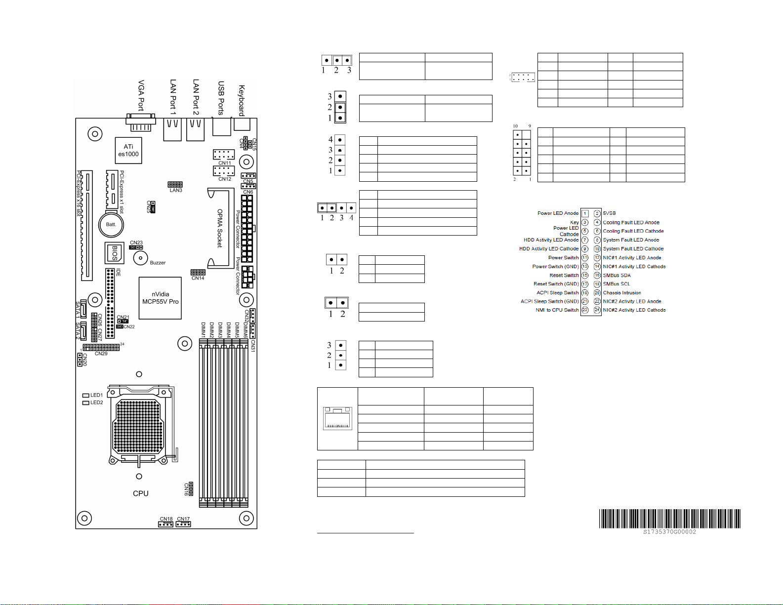
1.2.1 MB Quick Installation Guide
CN21 Clear CMOS Select Jumper
LAN Connector Indicator Light
Recommended Memory Configurations
1 DIMM Slot 5
2 DIMMs Slot 5, 6
4 DIMMs Slot 3, 4, 5, 6
6 DIMMs Slot 1, 2, 3, 4, 5, 6
The Latest BIOS, Manual, Memory AVL, Drivers and Utility can be
downloaded from
http://www.arima.com.tw/server
1-2 2-3
Clear CMOS
On-Board VGA Select Jumper
CN25
1-2 2-3
VGA Enabled
(default)
CN4 Mouse Header
Pin Description
1 GND
2 DATA
3 CLOCK
4 5V_DUAL
CN23 Speaker Header
Pin Description
1 Speaker
2 Buzzer
3 N/A
4 Speaker Power
CN15 Intrusion Function Pin Header
Pin Description
1 Intruder
2 GND
CN22 Flash Recovery Pin Header
1-2
Disable (default)
CN20 IPMI Header
Pin Description
1 FP_ID_LED
2 ALERT_CLEAR
3 FP_ALERT
State of Link
No link OFF OFF
Link @ 10Mbps OFF On
Link @ 100Mbps ON (Green) On
Link @ 1000Mbps ON (Orange) On
Activity ON BLINK
Normal
(default)
VGA Disabled
Speed LED
(Green/Orange)
Link/Activity
LED (Green)
CN11 / CN12 COM1 & COM2 Headers
Pin Description Pin Description
1 DCD 2 DSR
3 RX 4 RTS
5 TX 6 CTS
7 DTR 8 RI
9 GND 10 N/A
CN26 / CN27 USB Header
Pin Description Pin Description
1 VCC 2 VCC
3 USB_N0/2 4 USB_N1/3
5 USB_P0/2 6 USB_P1/3
7 GND 8 GND
9 10 N/A
CN29 Front Panel
Rev. 0.90
7
Page 8
1. To get MB jumper setting , please review NM12X MB Quick Installation
anual, Memory AVL, Drivers and Utility can be
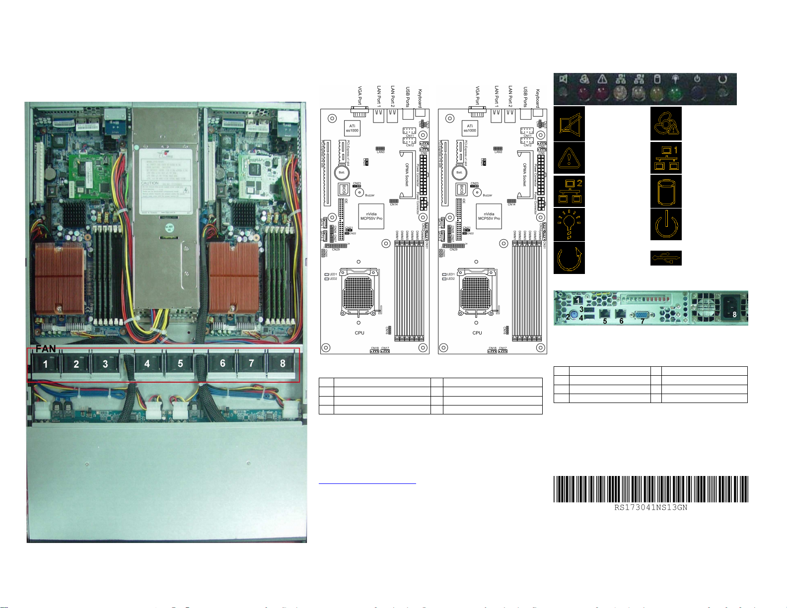
1.2.2 NK1231U Quick Installation Guide
MB : NK123 (Left)
MB : NK123 (Right)
Front Panel
FAN
1 MB 1 CPU FAN1 5 Power FAN 1
2 MB 1 CPU FAN2 6 MB 2 CPU FAN1
3 MB 1 Memory FAN 7 MB 2 CPU FAN2
4 Power FAN 1 8 MB 2 Memory FAN
Clear Switch
System Fault LED
NIC 2 LED
Power LED
Reset Switch
Rear Panel
1 NIC for OPMA 5 NIC 1
2 Keyboard 6 NIC 2
3 USB Port 1 7 VGA
4 USB Port 2 8 Power
FAN Fail LED
NIC 1 LED
HDD LED
Power Switch
USB
Guide
2. The Latest BIOS, M
downloaded from
http://www.arima.com.tw/server
8
Rev. 1.00
Page 9

1.3 System Specification
SYSTEM DETAILS:
Dimension: 665 x 432 x 43.5 mm
Two 10/100M RJ45 Connector on rear for OPMA
Eight System Fan with PWM
Two PCI-E x16 Riser Card
Four Ports GbE
SATA Backplane supports up to Four 3.5” Hot-Swap HDD
400W PSU with 80+% efficiency
24” Slide Rail
Indicator: (each Node) Power, HDD, Fan fault, System fault, LAN1, LAN2
SW/Connector: (each Node) Power, Reset, USB x2 Fault status Clear
SYSTEM MANAGEMENT:
ADM1026 Hardware Monitor onboard
OPMA connector supports Arima Scorpio II card (IPMI 2.0) and Arima Aquarius card (IPMI +
iKVM) server management daughter card (optional)
9
Page 10

1.4 Serverboard Specification
Processors
AMD Dual-Core Opteron 2000 series 90nm processors
-
2x1MB L2 cache
- Socket F LGA 1207-pin
- Support 16 Rank,
- Selectable TDP 120W or 95W or 68W
Supports up to 2000MT/s Hyper Transport
Supports AMD technologies: AMD64 technology, PowerNow Technology with OPM, AMD
Virtualization, Enhance Virus Protection & OPMA
Chipsets
nVidia nForce MCP55V Pro chipset
Winbond Super I/O W83627EHG chip
Analog Devices ADM1026 Hardware Monitor chip
Memory
Opteron 2000 socket F
6 Registered ECC DDR2 DIMM slots and a maximum 24GB of memory
Supports 512MB / 1GB / 2GB / 4GB @ 533 / 667 MHz modules, single or double-rank DIMMs
Expansion Slots
One PCI-Express x16 slot
One PCI-Express x1 slot (This slot had to use a FPC/Cable to add on card, can not plug card in
directly.)
One IPMI 2.0 connector
Integrated Graphics
ATI ES1000 with 32MB DDR/DDR2 memory (Dual Lay)
Gigabit Ethernet
Marvell Alaska 88E1116 Dual Port PHY with MCP55V Pro integrated MAC with TOE
function – Dual port 10/100/1000BASE-T PHY
Two single RJ-45 connector with LEDs
MCP55V Pro Integrated Serial ATA II Controller
2 ports connector, data transfers up to 3.0Gb/s (300MB/s)
Integrated nVidia MediaShield™ RAID to support RAID 0,1,10, 5, JBOD
MCP55V Pro Integrated ATA Controller
One PCI bus master channels for up to two enhanced IDE devices (40-pin)
Support for Ultra DMA 133/100/66/33 IDE drives and ATAPI compliant devices
Tri-state modes to enable swap bay
MCP55V Pro Integrated USB 2.0
Ten USB 2.0 ports (4 internal pin headers, and 2 front panel ports with Type A connector)
Super I/O
Winbond Super I/O W83627EHG chip
PS/2 mouse (internal pin-header) and PS/2 keyboard front panel connectors
Two 9-pin serial port (internal pin header)
Front Panel I/O
PS/2 keyboard connector
10
Page 11

One stacked connector contains two USB-2.0 ports
Two RJ-45 ports (one for GbE, one for GbE and IPMI shared)
DB15 Video connector
BIOS
4Mb Phoenix BIOS
Legacy USB support, all ports
SMBIOS 2.3.3 and DMI 2.0 compliant
Plug and Play (PnP)
APM (Advanced Power Management) 1.2
DMI (Desktop Management Interface) 2.1
ACPI (Advanced Configuration and Power Interface) 2.0
Fan Speed Control
PXE (Pre-Boot Execution)
Soft Power-down
Multiple boot support (with BIOS Boot Specification v3.1 (BBS) support) must be ready
console re-direct
After power failure (always on and last status, always off*)
System Management
IPMI 2.0 compliance (daughter card through 200 pin connector)
General management features required:
- CPU and Chassis environment temperature monitoring
- Fan speed control and Fan status monitoring
- Motherboard voltage monitoring
Fan header
Six 4 pins FAN headers with PWM control (Pin define: GND, FAN, 12V, PWM)
Form Factor
Half of SSI MEB form factor with size: 5.9” X 13”
Power
8-pin (+12V) and 24-pin power connector
11
Page 12
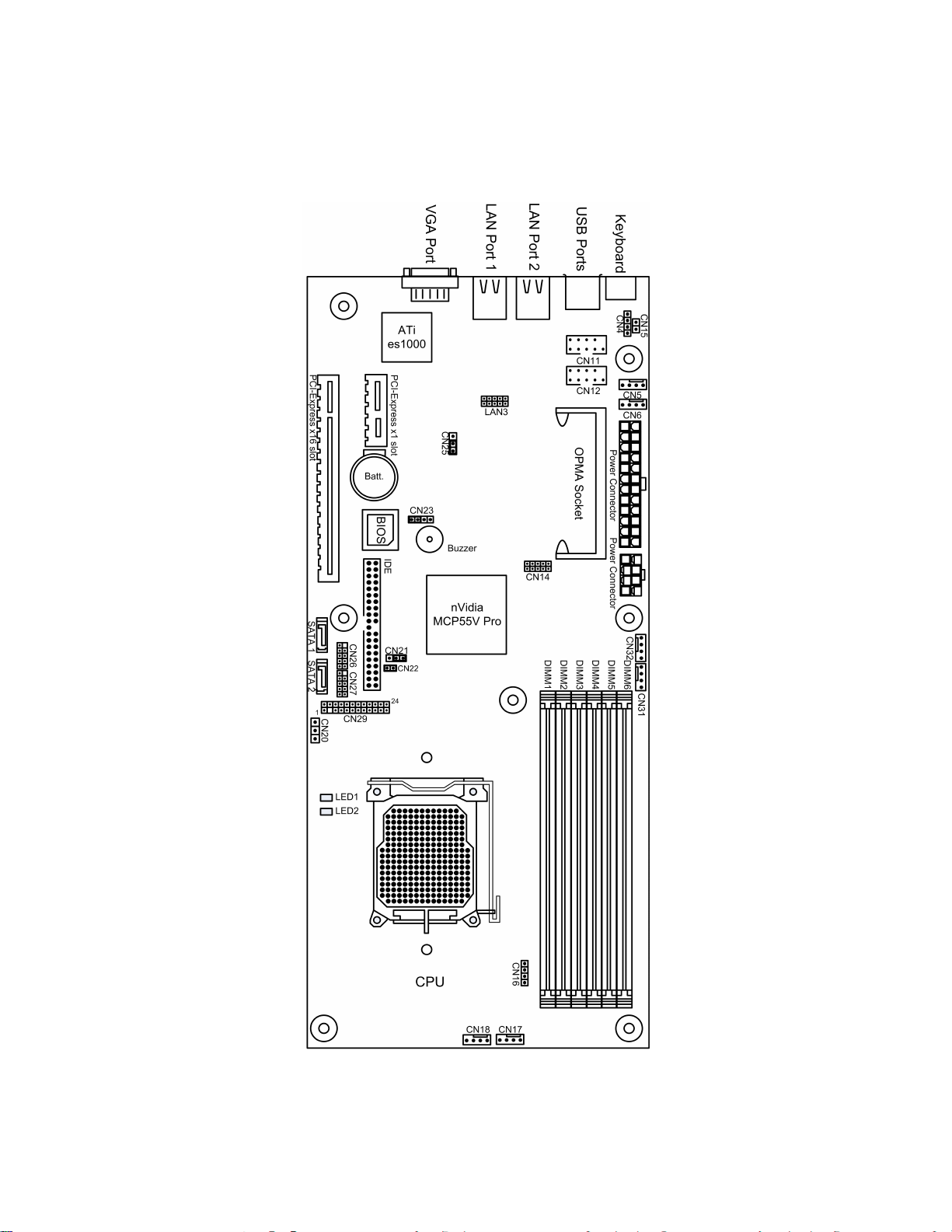
1.5 Serverboard Layout [Major Components]
The following diagram indicates all the major components of the serverboard.
12
Page 13
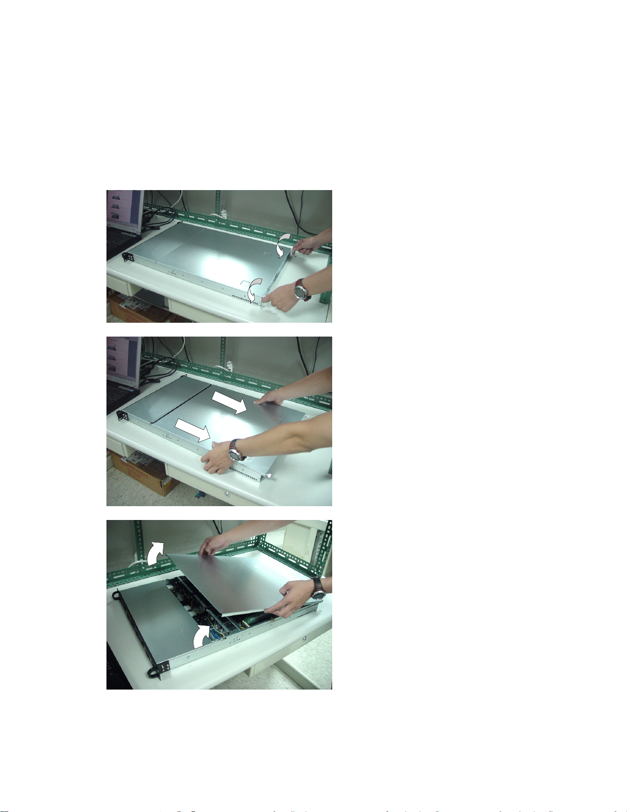
Chapter 2. Hardware Installation
2.1 System Installation
Step 1 Open The Case
1
Loose the screw on the edge of the top cover by
manual.
2
Press at the two sides of the top cover and slide the
cover backward
3
Pull out the top cover
13
Page 14
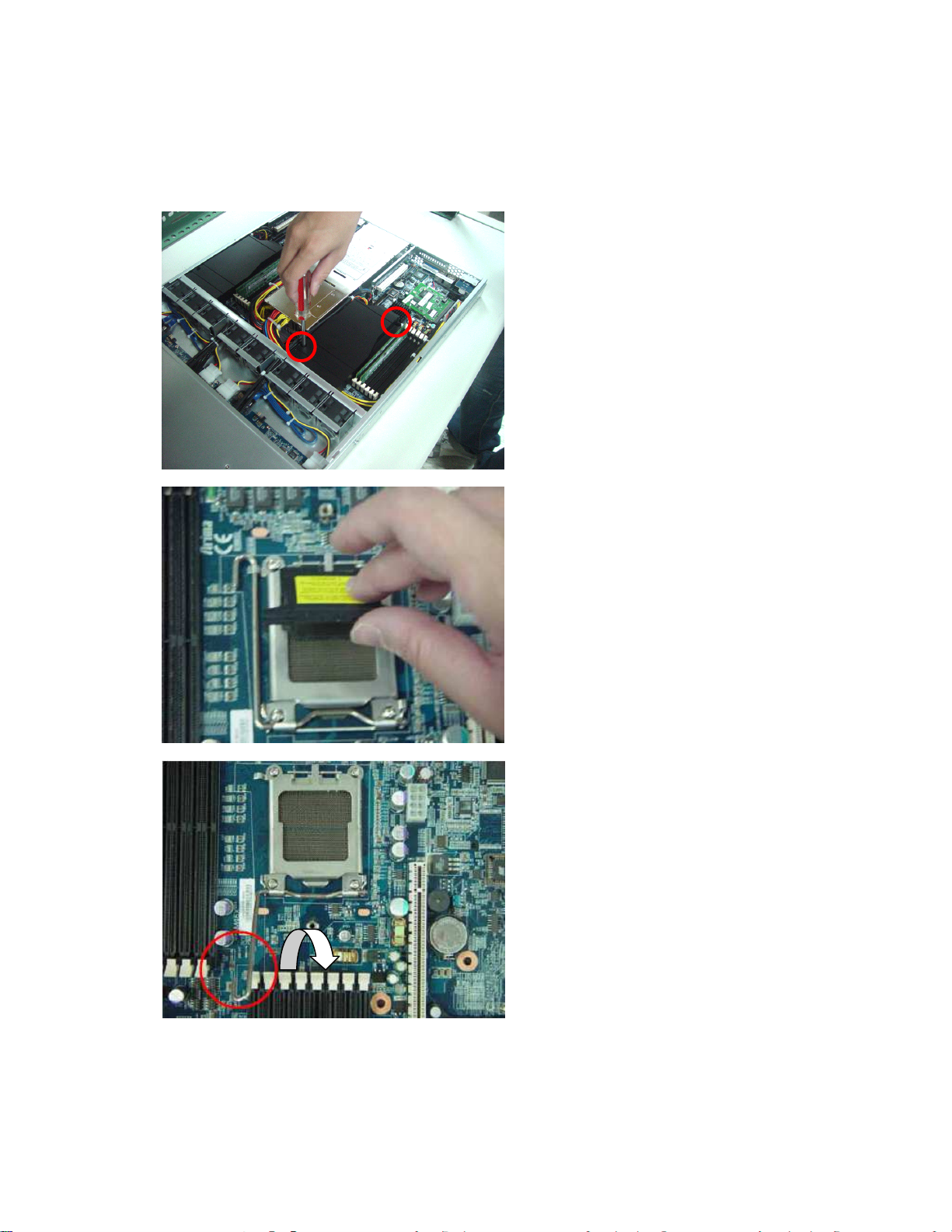
Step 2 Install CPU and CPU Heatsink
1
2
Loose the screws and lift up the Air duct
Locate the processor socket on the serverboard and
carefully remove the protective cover.
3
Pull the lever out of its locked position and let it
spring into its open position.
14
Page 15
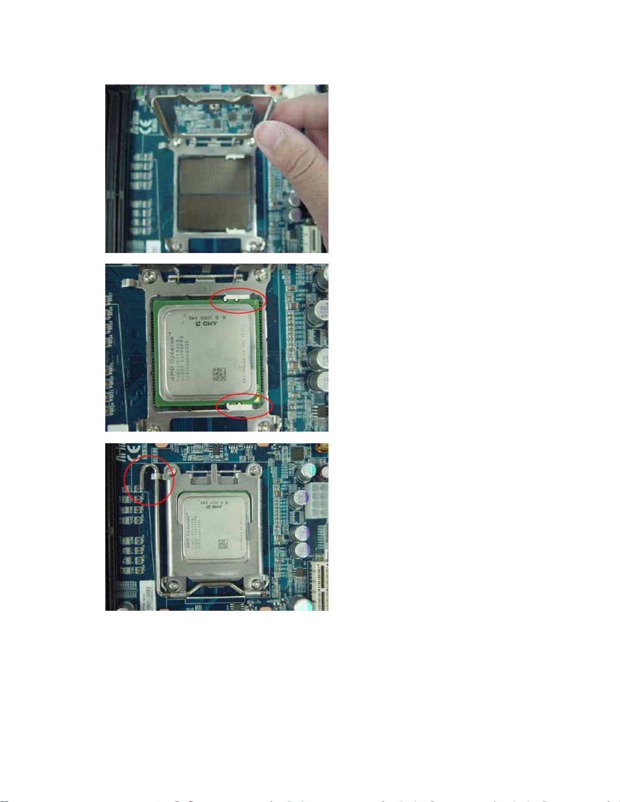
4
5
Now that the lever is in its unlocked position, lift
up the metal cover to reveal the CPU socket.
Place the CPU into the socket with the arrows
pointing to the bottom right of the socket as shown
(there are two gaps on both sides of the CPU,
make sure they fit perfectly into the socket. If it is
placed correctly, the CPU pins should be able to fit
into the socket perfectly).
6
Close the metal cover and return the lever into its
original locked position.
15
Page 16
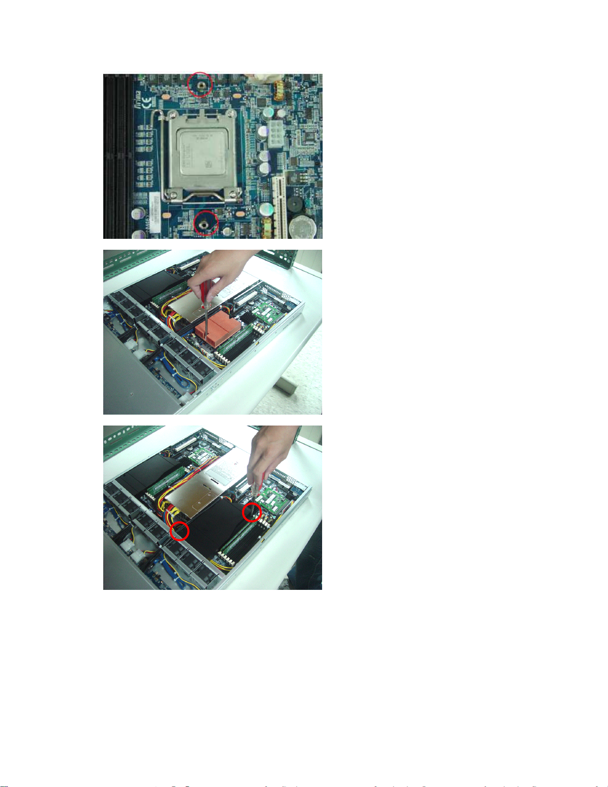
Now, rest the serverboard into the chassis, align
7
the two holes of the backplate with the two bolts of
the chassis.
8
9
Place the heatsink with the correct orientation and
secure heatsink with screws. Repeat this
installation procedure, when you are installing the
other CPU.
Install the Air Duct
16
Page 17
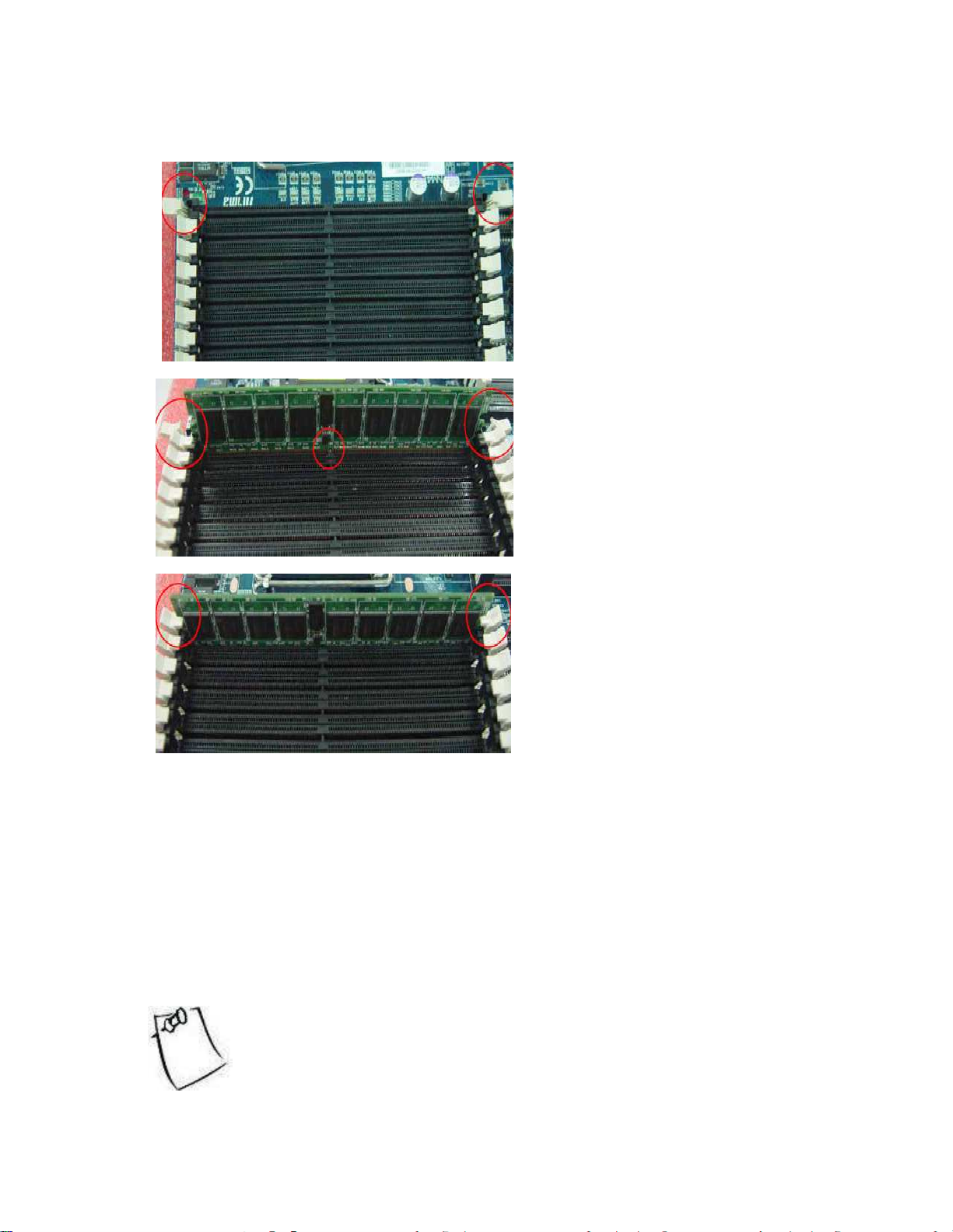
Step 3 Install Low Profile Registered DDR DRAM
Push in the memory module until
1
2
3
Open up the brackets
Line up the memory with socket. Make sure the gap
fits into the socket.
bracket can be closed securely onto the module.
Make sure the brackets hold onto the memory
module. Repeat this installation procedure, when
you are installing the other memory module.
The number of memory chips and how they are stacked on a memory
module do not indicate the rank of that memory module. The only
way to determine the rank of a memory module is to contact the
memory manufacturer for its specification.
17
Page 18
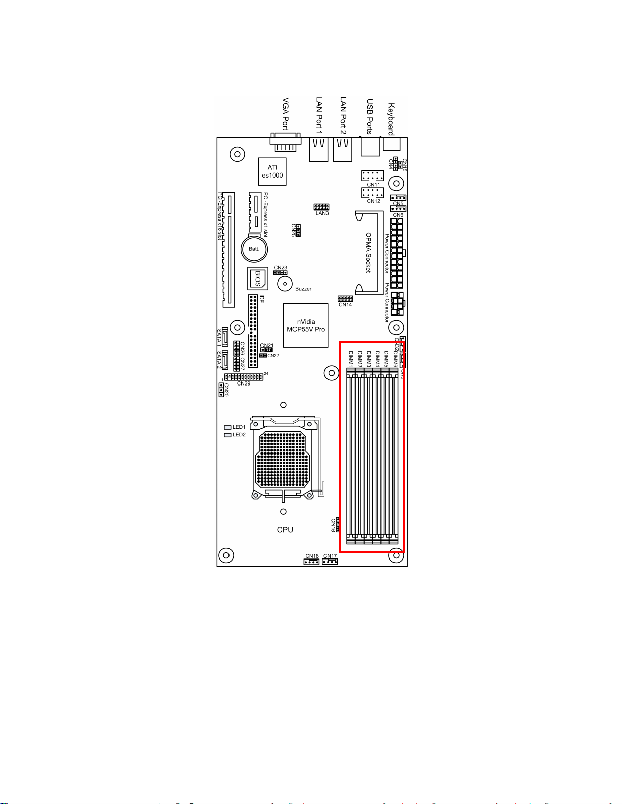
The diagram below shows the 6 DIMM slots from 1 to 6 for the CPU.
18
Page 19
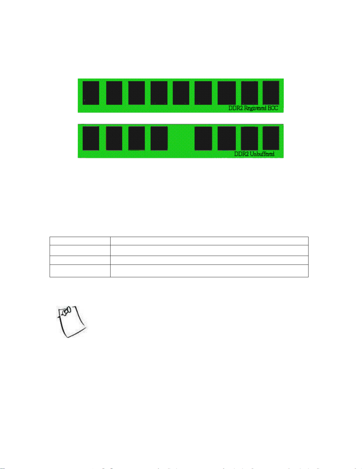
Types of memory supported:
There are 6 DIMM sockets for 240-pin 1.8-Volt DDR2 DIMMs (WILL ONLY SUPPORT Registered ECC
type memory module). Please note the diagrams below to identify if your DIMM memories are ECC or
non-ECC.
Before installing your memory sticks, please make sure that the memory sticks are compatible with the
NK12X 1U. The NK12X 1U will only support DDR2-667/533 modules. Please study the table below for
memory module specification of the NK12X 1U.
Key Notes:
DDR2 Memory Modules Supported: 512MB – 4GB (Registered ECC Only)
Installed memory will all be automatically detected (No jumpers or settings are needed)
NK12X supports up to 24GB in total
Unbuffered memory is NOT supported
1 DIMM Slot 5
2 DIMMs Slot 5, 6
4 DIMMs Slot 3, 4, 5, 6
6 DIMMs Slot 1, 2, 3, 4, 5, 6
Any configuration other than the recommended is not guaranteed to
work. Please refrain from using those configurations as we cannot
provide technical support on them.
19
Page 20
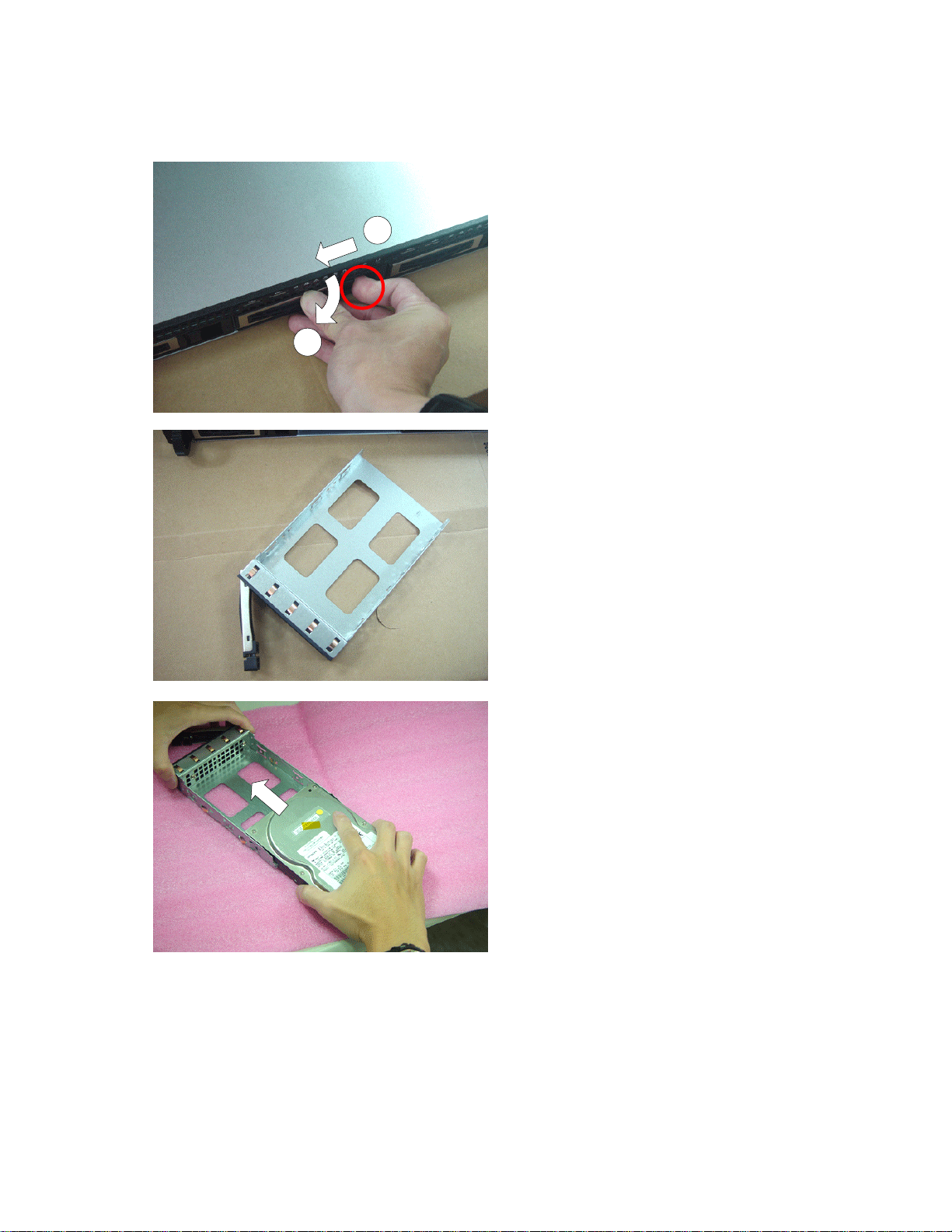
Step 4 Install HDDs
1
2
1
2
Press the thumb pad to the left and pull out the
HDD Tray
It is noted that there is no dummy case in the
HDD Tray.
3
Put the HDD bay on the flat table and slide the
hard disk into the tray with care.
20
Page 21

4
4
Secure the hard disk to the tray with four
screws.
Insert the hard disk and push the tray handle
back in place.
It is noted to press the thumb pad to the left and
push it into place until locked.
21
Page 22
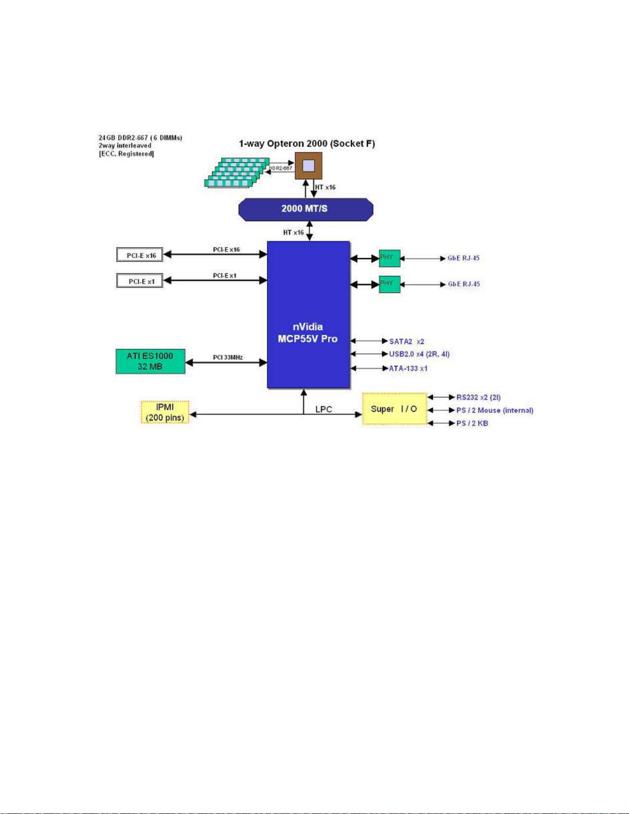
2.2 Block Diagram
22
Page 23
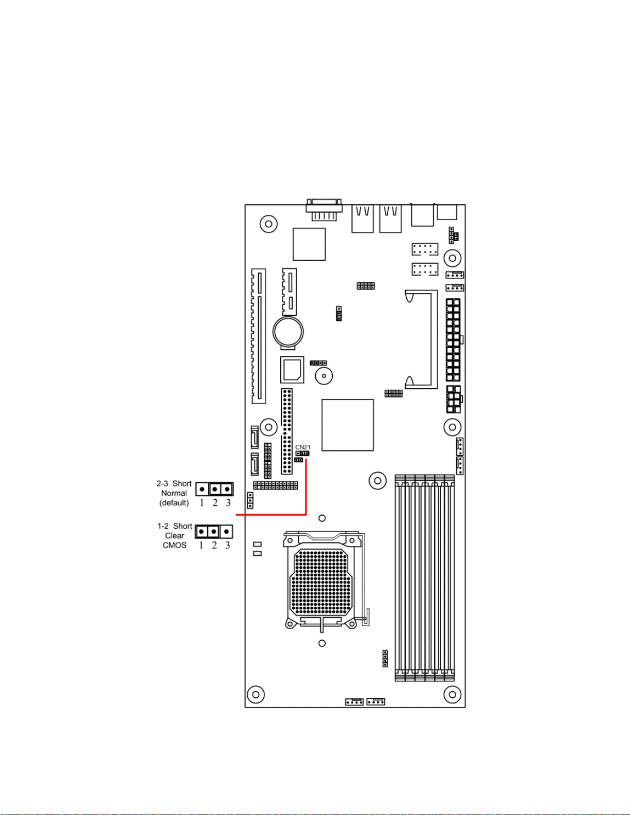
2.3 Jumper Configuration
2.3.1 Clear CMOS header
Header CN21 controls CMOS setting. Position your motherboard as it appears in the following diagram.
To clear CMOS:
1. Turn off the system, and make sure the standby power on the power supply has been turned off too.
2. Short pin 1 and pin 2 using a jumper for a few seconds, and switch back to pin 2 and pin 3 (as default).
3. Turn on the system and reconfigure the BIOS.
23
Page 24
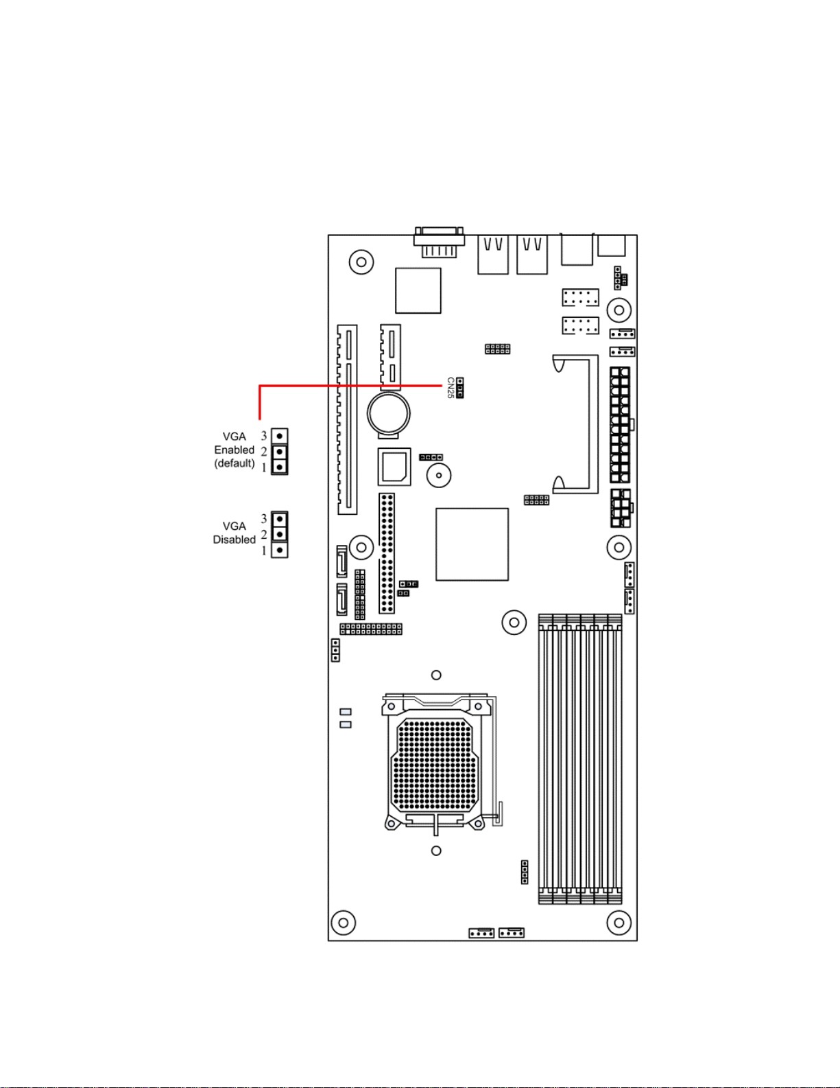
2.3.2 Enable onboard VGA header
Header CN25 controls the onboard VGA setting.
CN25 has the default set as enabled where pin 1 and pin 2 are short, and switch the jumper to pin 2 and pin
3 will disable onboard VGA. Refer to the following diagram for CN25 location:
24
Page 25
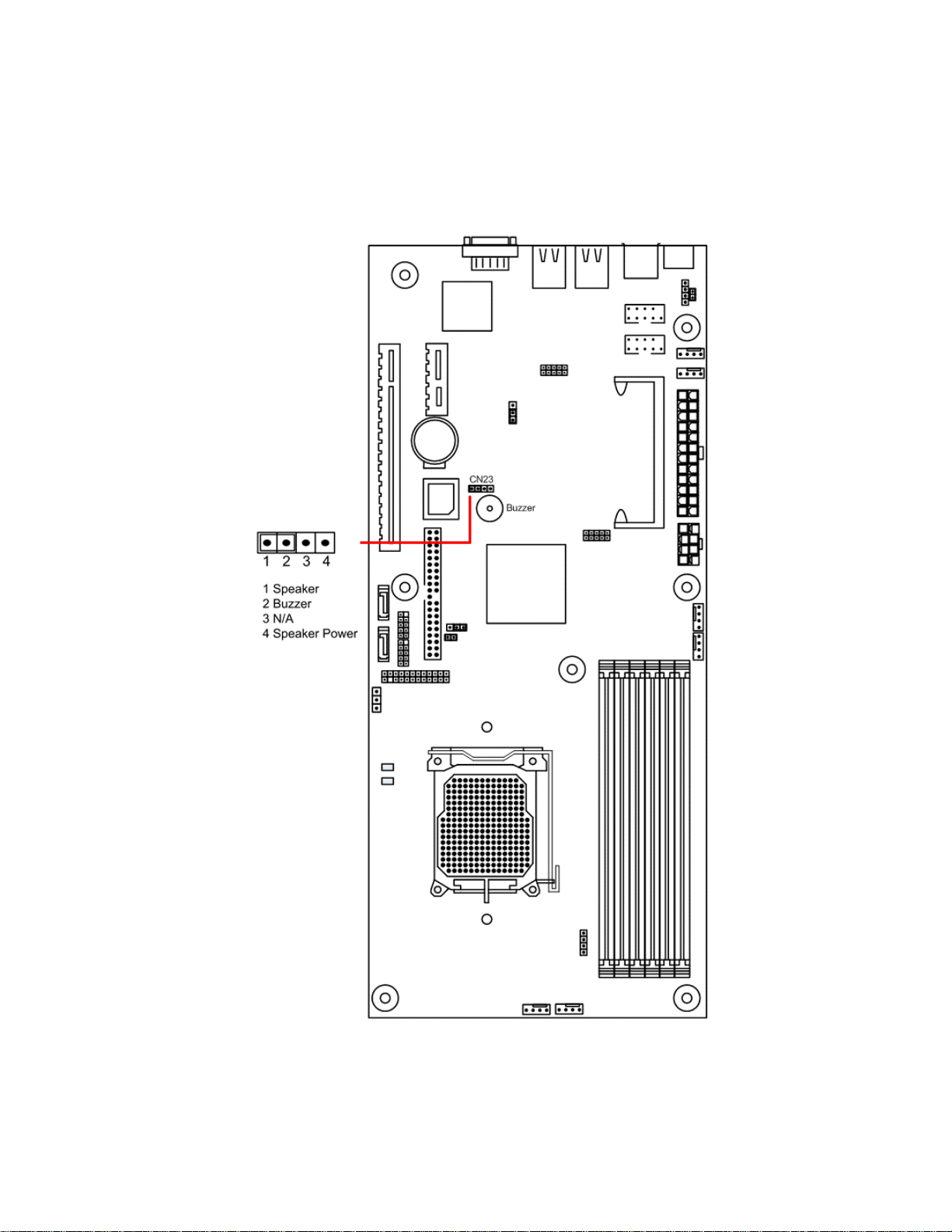
2.3.3 Onboard Buzzer
Header CN23 setting controls the on and off state of the onboard buzzer. Set jumper on 1-2 to enable the
buzzer.
25
Page 26
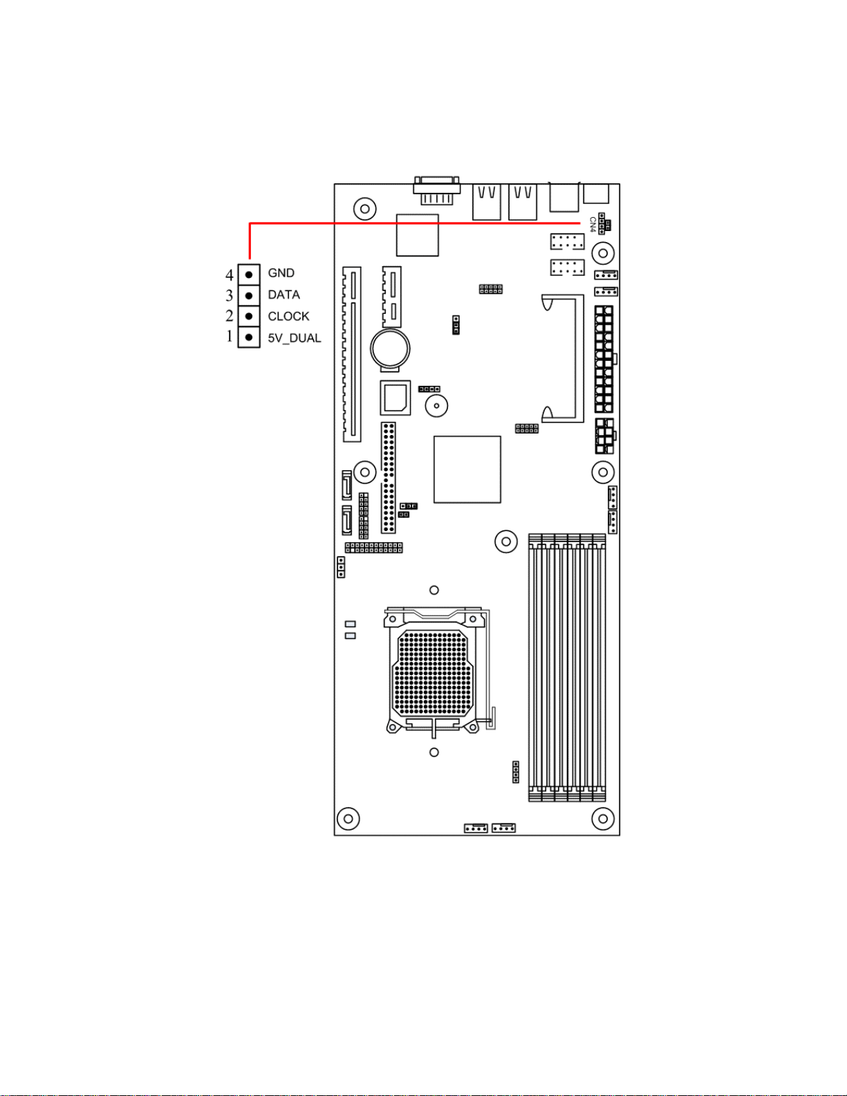
2.3.4 Mouse Header
CN4 is the pin header for mouse.
26
Page 27
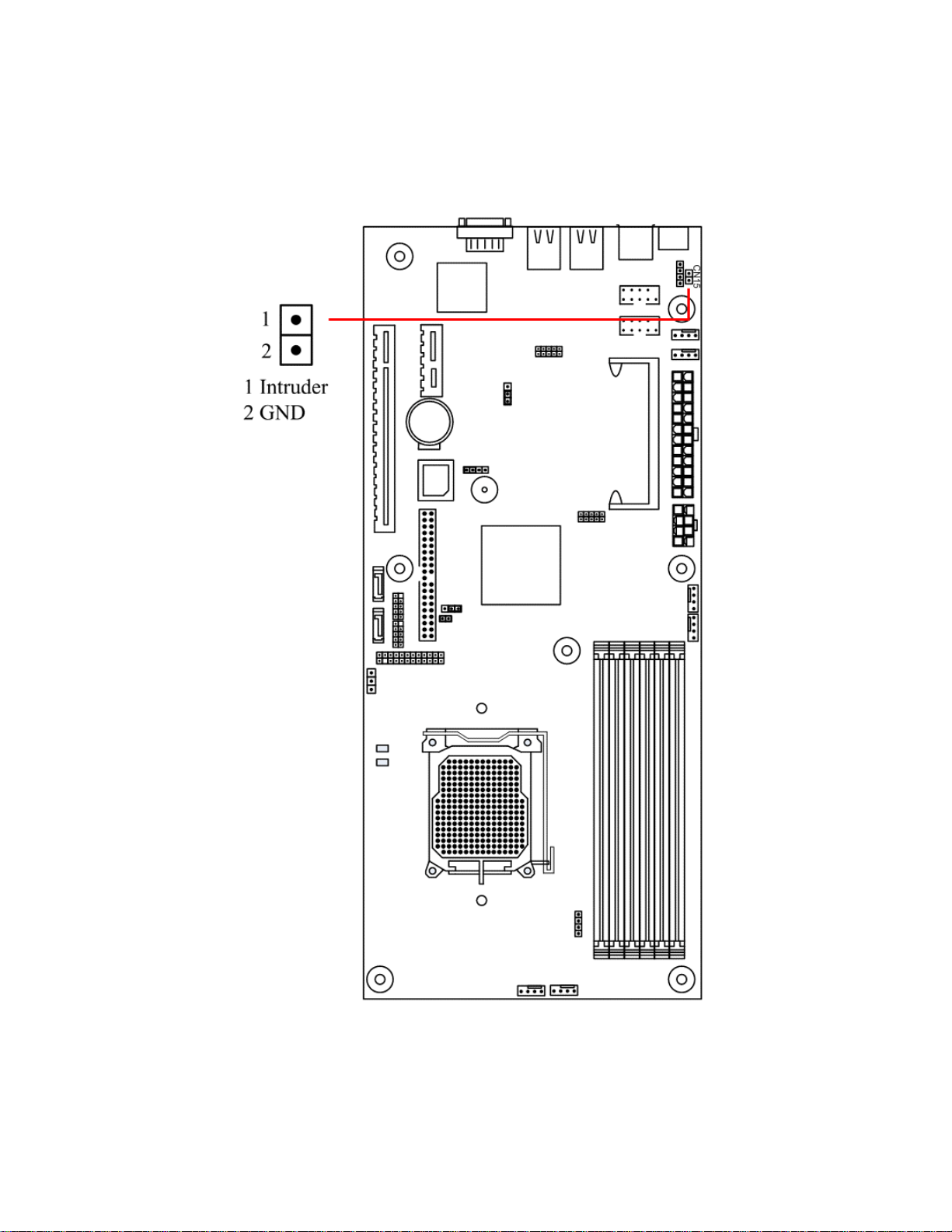
2.3.5 Intrusion Function Pin Header
Header CN15 controls the functionality of the onboard intrusion. Refer to the diagram below for the
locations of the headers.
27
Page 28
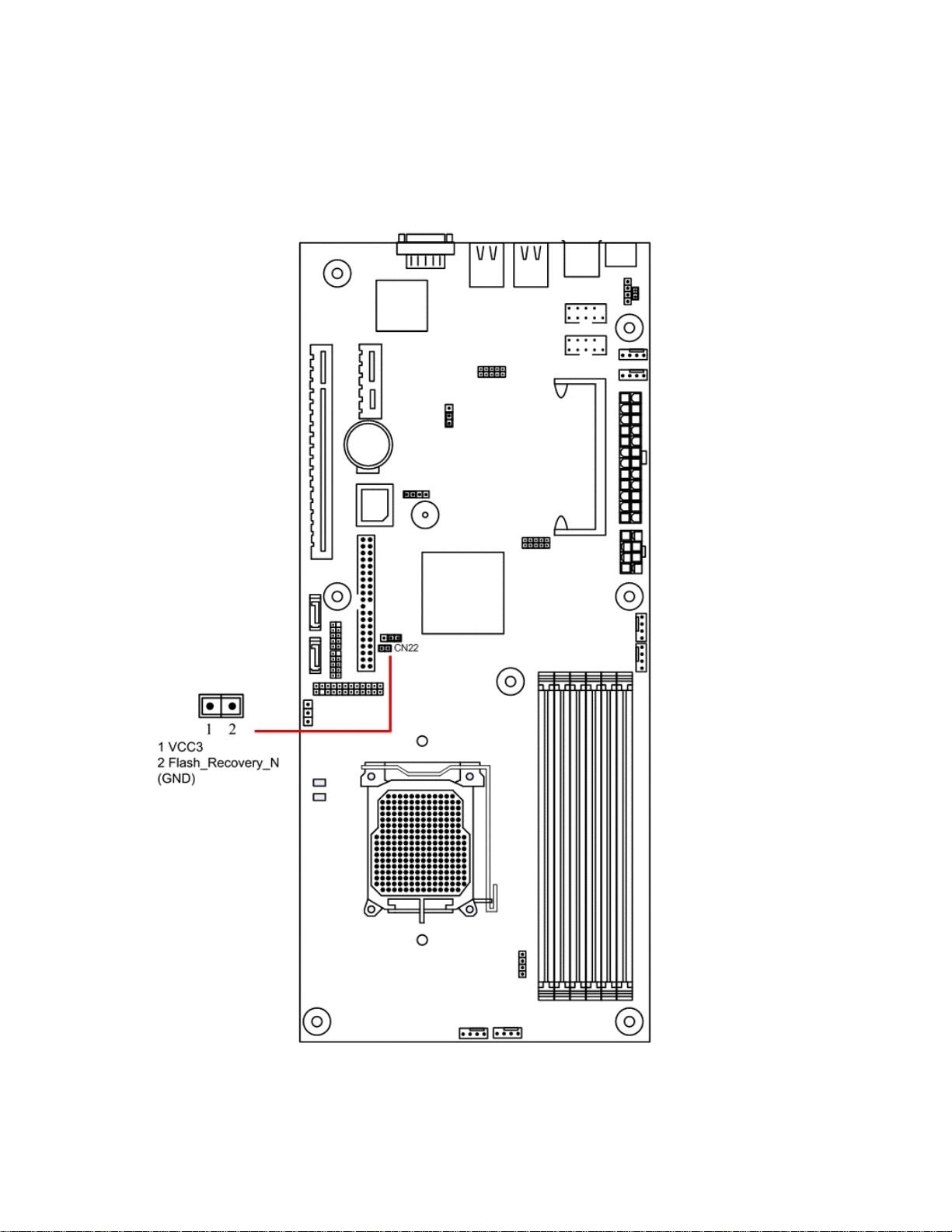
2.3.6 Flash Recovery Pin Header
Header CN22 is the pin header for flash recovery function.
28
Page 29
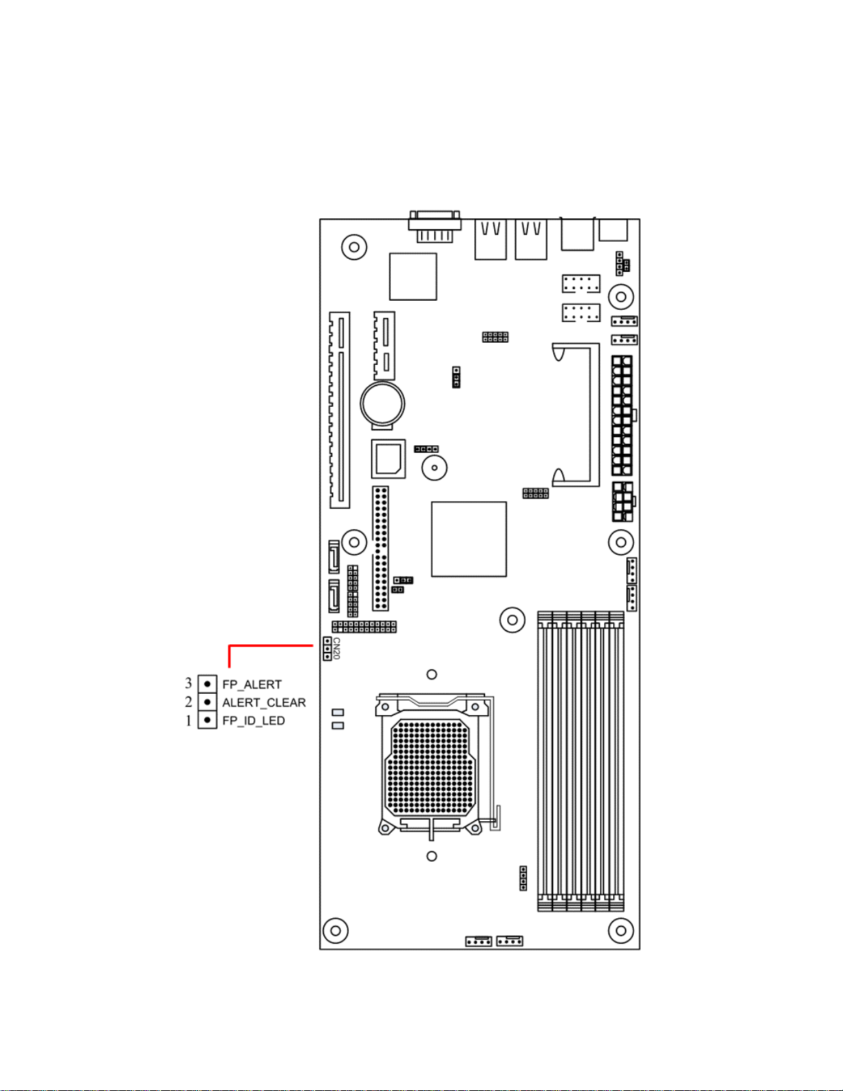
2.3.7 IPMI Header
Header CN20 is the pin header for IPMI.
29
Page 30
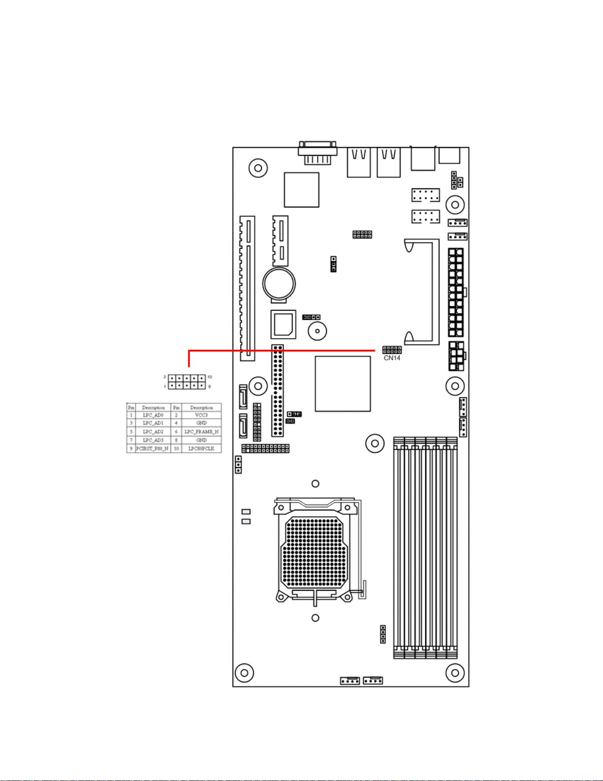
2.3.8 LPC Connector Header
Header CN14 is the pin header for LPC connector.
30
Page 31

2.4 Power Supply
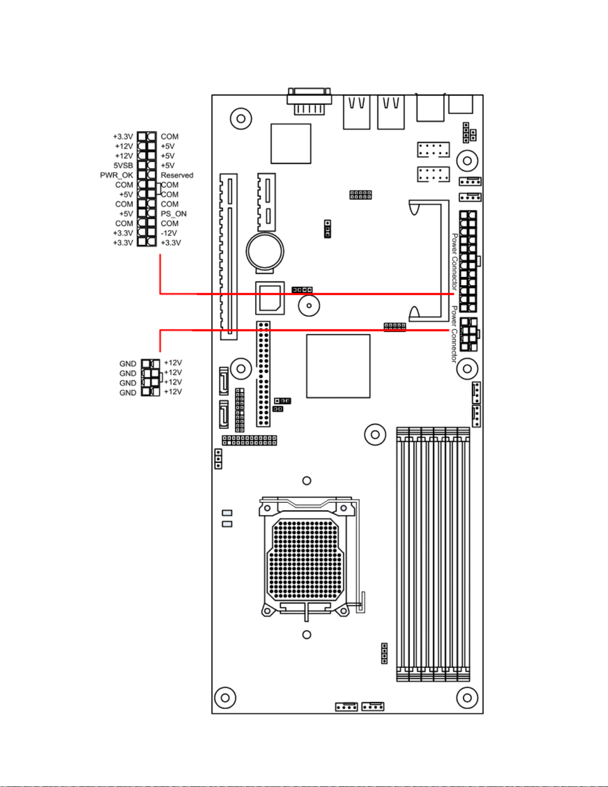
2.4.1 ATX 24-pin power connector and CPU 8/4-pin connector
There is one 24-pin power input connection and a 8/4-pin power input connection on the motherboard. The
24-pin power connection is used to connect to the power supply, while the 8/4-pin power connection is
used to power up the CPU. BOTH must be connected in order for the system to boot up. Make sure the
plugs are inserted into the connectors properly, to prevent any damage.
Please make sure your power supply can support at least 2 amps standby power for the Advanced
Configuration and Power Interface (ACPI) functions.
Make sure the AC adapter is not plugged into the wall outlet during
installation. The electric current could damage the motherboard.
Refer to the following diagram below for the connector locations.
31
Page 32
32
Page 33

2.5 Cables & Connectors
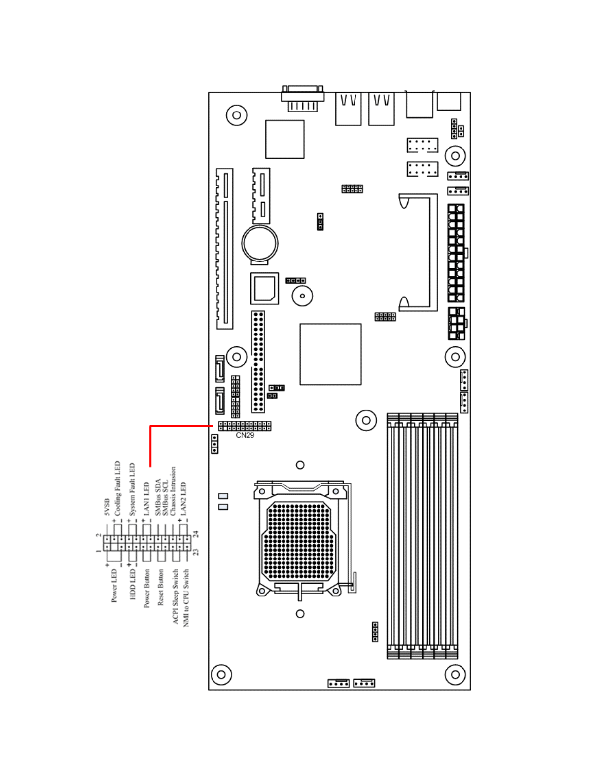
2.5.1 Front Panel Connectors
Power LED:
HDD Activity LED: This 2-pin connector attaches to the LED of the hard disk. The LED lights up
Power Switch:
Reset Switch:
ACPI Sleep Switch:
NMI to CPU Switch: This 1-pin connector connects to the switch that sends Non-Maskable Interrupt to
5 VSB:
Cooling Fault LED:
System Fault LED:
NIC#1 Activity LED: This connector connects to the LED that lights up when there is activity on Gbe
SMBus SDA:
SMBus SCL:
Chassis Intrusion:
NIC#2 Activity LED: This connector connects to the LED that lights up when there is activity on Gbe
This 3-pin connector attaches to the power LED.
when HDD is active.
This 2-pin connector attaches to the power button of the system.
This 2-pin connector attaches to the case-mounted reset switch for rebooting your
computer without turning on/off your power switch.
This 2-pin connector connects to the switch that can take the system into standby
mode when pressed.
the CPU. User can customize the button to perform a particular function.
This connector provides the user with power to any extra devices that uses 5 volt
power.
This connector connects to the LED that lights up when a problem arises with
cooling system.
This connector connects to the LED that lights up when a problem arises with the
system.
1.
A private bus to BMC chip for serial data, for use with BMC only.
A private bus to BMC chip for serial clock, for use with BMC only.
This connects to the mechanical switch that indicates whether the chassis had
been opened. User can activate it if desired.
2.
33
Page 34
34
Page 35
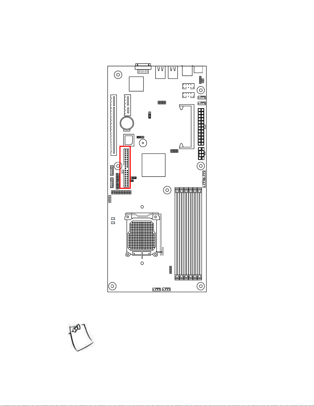
2.5.2 IDE connectors
The following diagram indicates the location of the IDE connector:
Read the instructions that come with the IDE drive and then consult the instructions here.
For Parallel ATA, installing IDE drives has become simpler over the years. The cables are now “keyed” to
guide the user to the correct installation configuration. Each IDE connector can support two IDE drives.
Remember to set BIOS to match the configuration that you implement
here. Go to Advanced Menu section of BIOS for detail.
35
Page 36
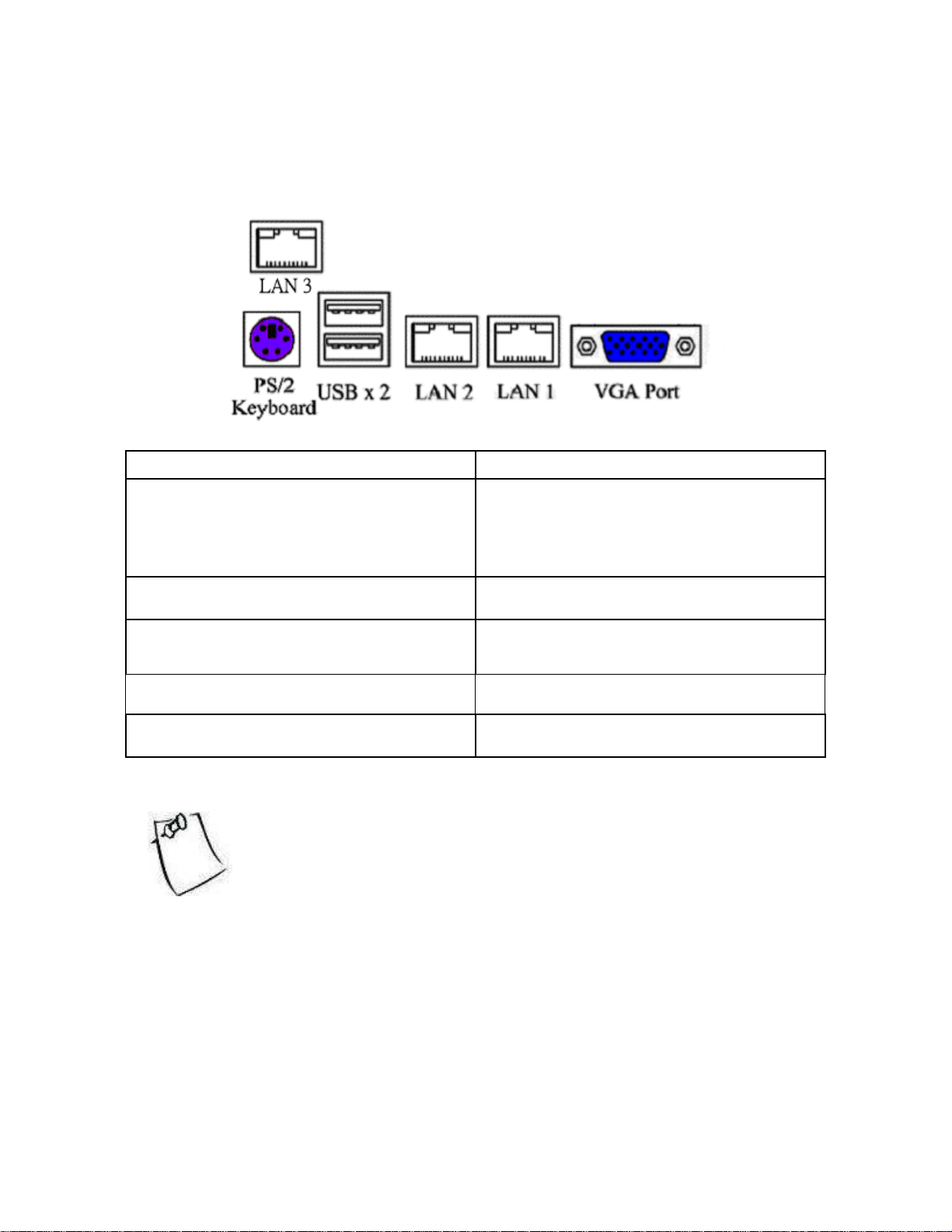
2.5.3 Rear Panel I/O ports
The following illustration displays the motherboard I/O port array.
Type of Port Function
PS/2 Keyboard connector This connection is for a standard keyboard using a
PS/2 plug (mini DIN). This connector will not
allow standard AT size (large DIN) keyboard
plugs. You may use a DIN to mini DIN adapter on
standard AT keyboards.
USB Ports Two external USB 2.0 ports that allow
simultaneous connections of 2 USB devices.
Gigabit Ethernet Port 1 & 2 These ports are RJ-45. The motherboard uses the
Marvell Alaska 88E1116 Dual Port PHY with
MCP55V Pro MAC with TOE function.
Ethernet Port 3 (OPMA) This port is RJ-45. This port is ONLY for OPMA,
not for regular network.
VGA connector (15-pin female) The VGA port connects display devices such as a
monitor. See the BIOS setup.
When Scorpio2 server management card* is implemented, plug LAN
cable into LAN1 for its function.
* Scorpio2 server management card is used for monitoring and
recording of system component values such as system voltages, fan
speed, and CPU/system temperature.
36
Page 37
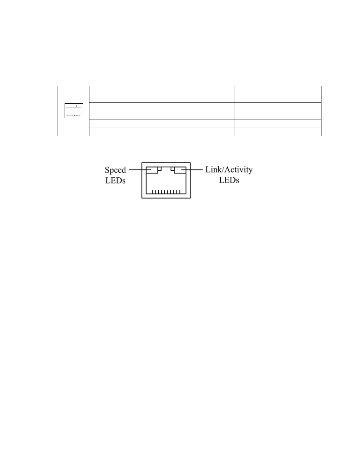
2.5.4 Back Panel LAN LED
Back Panel LAN LED:
The table below will allow the user to monitor LAN activities from the back of the system.
RJ-45 connectors LEDs
State of Link Speed LED (Green/Orange) Link/Activity LED (Green)
No link OFF OFF
Link @ 10Mbps OFF On
Link @ 100Mbps ON (Green) On
Link @ 1000Mbps ON (Orange) On
Activity ON BLINK
37
Page 38
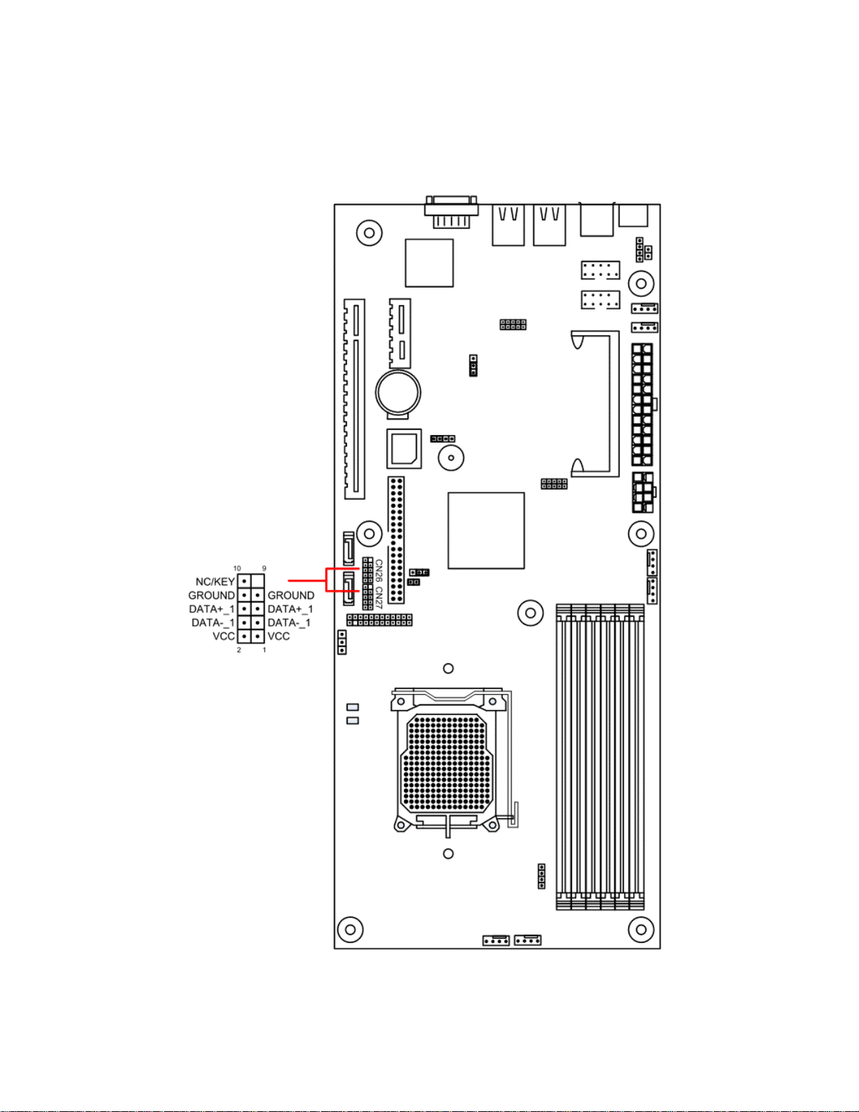
2.5.5 Front USB Connector
Header CN26 and CN27 control two front USB connections. To activate the front USBs, connect the USB
wires to CN26 or CN27. Refer to the following diagram for the location of CN26 and CN27.
38
Page 39
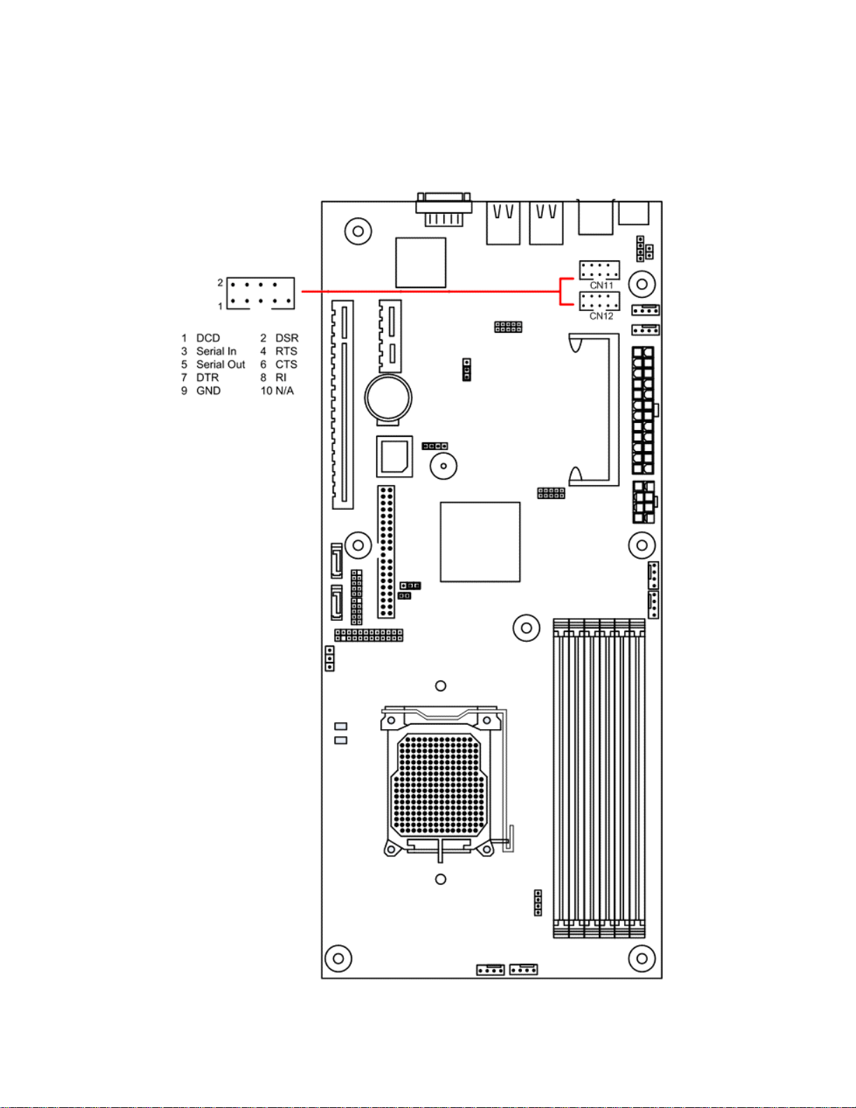
2.5.6 Front Panel Serial Port Connector
Header CN11 (COM1) and CN12 (COM2) control the activation of front panel serial port. Refer to the
following diagram for location and orientation of CN11 and CN12.
39
Page 40

Chapter 3. BIOS Setup
This chapter discusses the PhoenixBIOS setup program built into the ROM BIOS.
BIOS is the basic input/output system, the firmware on the motherboard that enables the hardware to
interact with the software. The setup program allows the users to modify the basic system configurations
according to their needs. The configuration is then stored in a battery-backed NVRAM so that it retains the
configuration even when the power is turned off. The PhoenixBIOS installed in the motherboard’s ROM is
a custom version of an industry standard BIOS.
The rest of the chapter will list all the menus and sub-menus in the BIOS. Along with them, you can also
find the list of varieties for any configurable item in the BIOS.
3.1 Entering BIOS Setup
The PhoenixBIOS is activated when the system powers on. The BIOS reads the system information
contained in the CMOS and begins the process of checking the system and configuring it. After finishing
configuring the whole system, BIOS will seek an OS on disk and turn over control of the system to the OS
found.
While BIOS is in control, the Setup menu can be accessed by pressing the <F2> key when the following
message appears briefly at the bottom of the screen during Power On Self Test: “Press <F2> to enter
SETUP.”
40
Page 41

3.2 Using Setup
The following table provides details about how to navigate the Setup program using keyboard.
KEY FUNCTION
Up Arrow ↑
Move to the previous item.
Down Arrow ↓
Left Arrow ←
Right Arrow →
Esc In the sub-menu: Exit the sub-menu.
Enter Select the item. A pop-up window will appear to allow setting of the item’s
+ Increase the numeric value or goes to the previous setting value.
- Decrease the numeric value or goes to the next setting value.
F1 General help on setup navigation keys. Press <F1> key to pop up a small
F9 Setup Defaults.
F10 Save and Exit.
Move to the next item.
Move to the previous menu.
Move to the next menu.
In the main menu: Exit without saving.
value. If the item has a ► in front of it, it means that the item leads to a submenu. Pressing <Enter> will take you to the sub-menu.
help window that describe the appropriate keys to use and the possible
selections for the highlighted item. To exit the Help Window, press <ESC>
key or <F1> key again.
41
Page 42

3.3 Troubleshooting
In case the system cannot be booted after some changes in BIOS, use the clear CMOS jumper setting to
reset the BIOS to default (See Page 22). To avoid such problem, configure only the items that you
thoroughly understand and refrain from modifying the advanced settings.
42
Page 43

3.4 Main Menu
Phoenix TrustedCore(tm) Setup Utility
Main Advanced Security Power Boot Server Exit
Item Specific Help
System Time: [10:14:38]
System Date: [12/19/2006]
BIOS Date 11/09/06
BIOS Version: NK12X V051 NFORCE
System Memory: 633 KB
Extended Memory: 2046 MB
<Tab>, <Shift Tab>, or
<Enter> selects field.
F1 Help
↑↓
Select Item -/+ Change Values F9 Setup Defaults
Esc Exit Select Menu Enter Select ► Sub-Menu F10 Save and Exit
The following table shows the items that you can customize on the Main menu page:
Item Options Description
System Time No options. Shows the time of the day in
the format of Hour/Min/Sec.
System Date No options. Shows the date in the format of
MM/DD/YYYY.
BIOS Date No options. Shows the release date of the
BIOS.
BIOS Version No options. Version of the BIOS.
System Memory No options. This item is not configurable to
user.
Extended Memory No options. This item is not configurable to
user.
43
Page 44
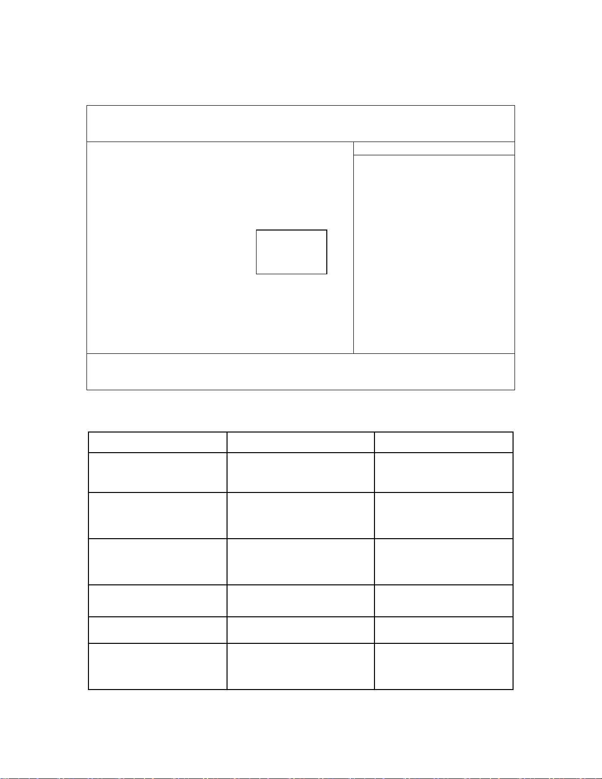
3.5 Advanced Menu
Phoenix TrustedCore(tm) Setup Utility
Main Advanced Security Power Boot Server Exit
Item Specific Help
MCFG Table: [Disabled]
Reset Configuration Data: [No]
QuickBoot Mode: [Enabled]
Summary screen: [Disabled]
► Hammer Configuration
► Integrated Devices
► IDE Configuration Disabled
► I/O Device Configuration Enabled
► Console Redirection
IOMMU: [Disabled]
DRAM Bank Interleave [Auto]
Enable/Disable MCFG Table
F1 Help
↑↓
Select Item -/+ Change Values F9 Setup Defaults
Esc Exit Select Menu Enter Select ► Sub-Menu F10 Save and Exit
The following table shows the items that you can customize on the Advanced menu page:
Item Options Description
MCFG Table Disabled
Enabled
Reset Configuration Data No
Yes
QuickBoot Mode Disabled
Enabled
Summary screen Disabled
Enabled
IOMMU Disabled
Enabled
DRAM Bank Interleave Disabled
Auto
Enable/Disable MCFG Table
Select ‘Yes’ if you want to
clear the Extended System
Configuration Data (ESCD)
area.
Allows the system to skip
certain tests while booting.
This will decrease the time
needed to boot the system.
Display system configuration
on boot.
Enable \ Disable IOMMU
Interleave memory blocks
across the DRAM chip
selects. Auto will set this
enabled when possible.
44
Page 45
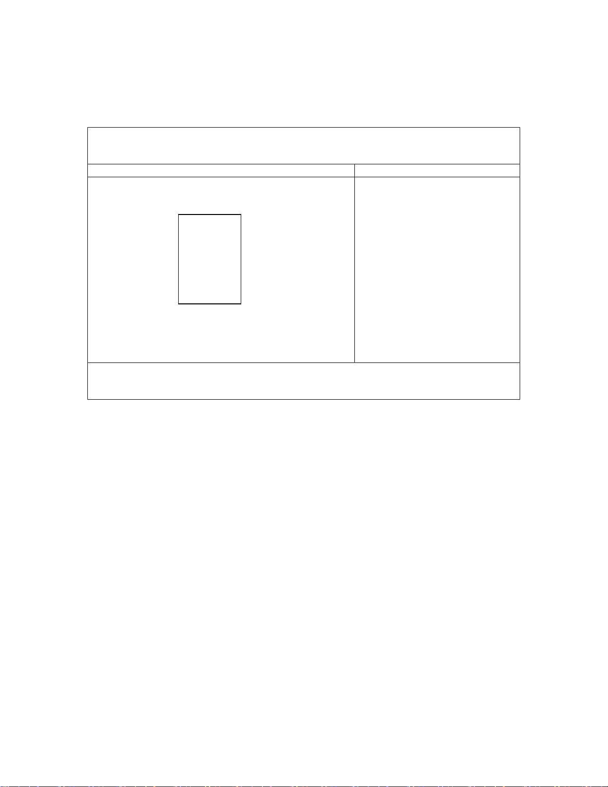
3.5.1 Hammer Configuration Sub-Menu
The Hammer Configuration sub-menu is shown in following figure:
Phoenix TrustedCore(tm) Setup Utility
Advanced
Hammer Configuration Item Specific Help
HT-LDT Frequency: [1000Mhz]
200Mhz
400Mhz
600Mhz
800Mhz
1000Mhz
Set frequency of HT
links for coherent
and non-coherent.
F1 Help
Esc Exit Select Menu Enter Select ► Sub-Menu F10 Save and Exit
↑↓
Select Item -/+ Change Values F9 Setup Defaults
45
Page 46
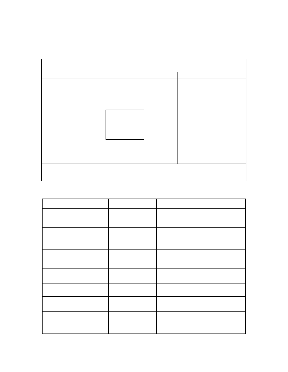
3.5.2 Integrated Devices Sub-Menu
The Integrated Devices sub-menu should look like following:
Phoenix TrustedCore(tm) Setup Utility
Advanced
Integrated Devices Item Specific Help
USB Control [USB1.1+USB2]
USB BIOS Legacy Support: [Enabled]
MAC LAN: [Enabled]
MAC LAN Bridge: [Enabled]
MAC 1 LAN: [E
MAC 1 LAN Bridge: [E Disabled
SATA1 Controller: [E USB1.1
USB1.1+USB2
► NV RAID Configuration
Enable/Disable USB
Controllers.
F1 Help
↑↓
Select Item -/+ Change Values F9 Setup Defaults
Esc Exit Select Menu Enter Select ► Sub-Menu F10 Save and Exit
The following table shows the items that you can customize on the Integrated Devices sub-menu page:
Item Options Description
USB Control Disabled
USB1.1
USB1.1+USB2
USB BIOS Legacy Support Disabled
Enabled
MAC LAN Enabled
Disabled
MAC LAN Bridge Disabled
Enabled
MAC 1 LAN Enabled
Disabled
MAC 1 LAN Bridge Disabled
Enabled
Enable/Disable USB Controllers.
Enables or Disables support for USB
Keyboards and Mice. (Enable for use with
a non-USB aware Operating System such
as DOS or UNIX)
Enabled/Disable MAC LAN Device
Enable MAC Lan Bridge
Enabled/Disable MAC 1 LAN Device
Enable MAC 1 Lan Bridge
SATA Controller Enabled
Disabled
Enable/Disable First Serial ATA Device
NOTE: Mobile platform, Enable SATA,
Save and Exit BIOS SETUP. Then must
do a power cycle during next POST.
46
Page 47
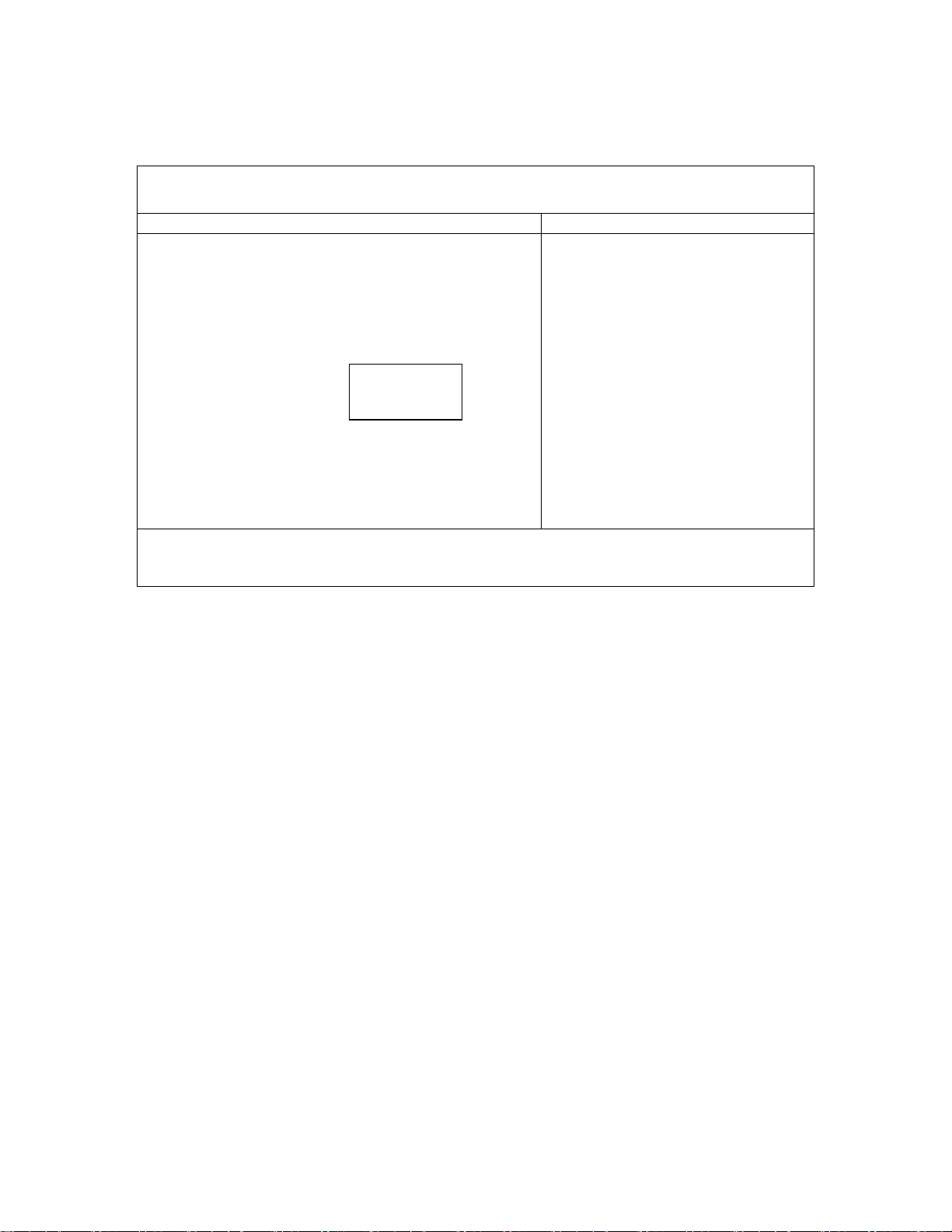
Following figure shows the NV RAID Configuration sub-menu:
Phoenix TrustedCore(tm) Setup Utility
Advanced
NV RAID Configuration Item Specific Help
NV RAID Configuration: [Disabled]
Enabled/Disable
Nvidia RAID control.
SATA controller must
be enabled for RAID
feature to function.
Disabled
Enabled
Enabling Master SATA0
Secondary requires
enabling Secondary SATA
Channel.
F1 Help
↑↓
Select Item -/+ Change Values F9 Setup Defaults
Both options are listed
in Integrated Devices.
Esc Exit Select Menu Enter Select ► Sub-Menu F10 Save and Exit
47
Page 48

3.5.3 IDE Configuration Sub-Menu
The IDE Configuration sub-menu looks like the following:
Phoenix TrustedCore(tm) Setup Utility
Advanced
IDE Configuration Item Specific Help
► Primary Master [None]
► Primary Slave [None]
F1 Help
↑↓
Select Item -/+ Change Values F9 Setup Defaults
Esc Exit Select Menu Enter Select ► Sub-Menu F10 Save and Exit
Primary Master/Primary Slave sub-menu:
Phoenix TrustedCore(tm) Setup Utility
Advanced
Primary Master [None] Item Specific Help
Type: [Auto]
Multi-Sector Transfers: [Disabled]
LBA Mode Control: [Disabled]
32 Bit I/O: [Disabled]
Transfer Mode: [Standard]
Ultra DMA Mode: [Disabled]
User = you enter
parameters of hard-disk
drive installed at this
connection.
Auto = autotypes
hard-disk drive
installed here.
CD-ROM = a CD-ROM drive
is installed here.
ATAPI Removable =
removable disk drive is
installed here.
F1 Help
↑↓
Select Item -/+ Change Values F9 Setup Defaults
Esc Exit Select Menu Enter Select ► Sub-Menu F10 Save and Exit
48
Page 49

The table below is a list of items that you can customize in the Primary Master/Primary Slave options under
IDE Configuration sub-menu.
Item Options Description
Type Auto
None
CD-ROM
ATAPI Removable
IDE Removable
Other ATAPI
User
User = you enter parameters
of hard-disk drive installed at
this connection.
Auto = autotypes hard-disk
drive installed here.
CD-ROM = a CD-ROM drive
is installed here.
ATAPI Removable =
removable disk drive is
installed here.
Multi-Sector Transfers
LBA Mode Control
Disabled
2 Sectors
4 Sectors
8 Sectors
16 Sectors
Disabled
Enabled
Specify the number of sectors
per block for multiple sector
transfers. ‘MAX’ refers to the
size the disk returns when
queried.
Enabling LBA causes Logical
Block Addressing to be used
in place of Cylinders, Heads
& Sectors.
32 Bit I/O
Transfer Mode
Disabled
Enabled
Standard
Fast PIO 1
Fast PIO 2
Fast PIO 3
This setting enables or
disables 32 bit IDE data
transfers.
Select the method for moving
data to/from the drive.
Autotype the drive to select
the optimum transfer mode.
Fast PIO 4
FPIO 3/DMA 1
FPIO 4/DMA 2
Ultra DMA Mode
Disabled
Mode 0
Mode 1
Mode 2
Mode 3
Selects the Ultra DMA mode
used for moving data to/from
the drive. Autotype the drive
to select the optimum transfer
mode.
Mode 4
Mode 5
Mode 6
49
Page 50

3.5.4 I/O Device Configuration Sub-Menu
The I/O Device Configuration sub-menu looks like the following:
Phoenix TrustedCore(tm) Setup Utility
Advanced
I/O Device Configuration Item Specific Help
Serial port A: [Enabled]
Base I/O address: [3F8]
Interrupt: [IRQ 4]
Serial port B: [Disabled]
Configure serial port A
using options:
[Disabled]
No configuration
[Enabled]
User configuration
[Auto]
BIOS or OS chooses
configuration
(OS Controlled)
Displayed when
controlled by OS
F1 Help
↑↓
Select Item -/+ Change Values F9 Setup Defaults
Esc Exit Select Menu Enter Select ► Sub-Menu F10 Save and Exit
The following table shows the items that you can customize on the I/O Device Configuration sub-menu
page:
Item Options Description
Serial port A Disabled
Enabled
Auto
Base I/O address 3F8
2F8
3E8
2E8
Interrupt IRQ 3
IRQ 4
Serial port B Disabled
Enabled
Auto
Disabled - No configuration.
Enabled - User configuration.
Auto - BIOS or OS chooses
configuration.
Set the base I/O address for
serial port A.
Set the interrupt for serial port
A.
Disabled - No configuration.
Enabled - User configuration.
Auto - BIOS or OS chooses
configuration.
50
Page 51

3.5.5 Console Redirection Sub-Menu
The Console Redirection sub-menu looks like the following:
Phoenix TrustedCore(tm) Setup Utility
Advanced
Console Redirection Item Specific Help
Com Port Address [Disabled]
Baud Rate [19.2K]
Console Type [PC ANSI]
Flow Control [CTS/RTS]
Console connection: [Direct]
Continue C.R. after POST: [Off]
If enabled, it will
use a port on the
motherboard.
F1 Help
↑↓
Select Item -/+ Change Values F9 Setup Defaults
Esc Exit Select Menu Enter Select ► Sub-Menu F10 Save and Exit
The following table shows the items that you can customize on the Console Redirection sub-menu page:
Item Options Description
Com Port Address Disabled
On-board COM A
On-board COM B
Baud Rate 300
1200
2400
9600
19.2K
38.4K
57.6K
115.2K
Console Type VT100
VT100, 8BIT
PC ANSI, 7BIT
PC ANSI
VT100+
VT UTF8
ASCII
Flow Control None
XON/XOFF
CTS/RTS
Console connection Direct
Via modem
Continue C.R. after POST Off
On
If enabled, it will use a port on the
motherboard.
Enables the specified baud rate.
Enables the specified console type.
Enables Flow Control
Indicate whether the console is
connected directly to the system or
a modem is used to connect.
Enables Console Redirection after
OS has loaded.
51
Page 52

3.6 Security Menu
The Security Menu is shown as the following figure:
Phoenix TrustedCore(tm) Setup Utility
Main Advanced Security Power Boot Server Exit
Item Specific Help
Supervisor Password Is: Clear
User Password Is: Clear
Boot-time Diagnostic Screen: [Enabled]
Set Supervisor Password [Enter]
Set User Password [Enter]
F1 Help
↑↓
Select Item -/+ Change Values F9 Setup Defaults
Esc Exit Select Menu Enter Select ► Sub-Menu F10 Save and Exit
The following table shows the items that you can customize on the Security Menu page:
Item Options Description
Boot-time Diagnostic Screen Disabled
Enabled
Display the diagnostic
screen during boot
Display the diagnostic screen
during boot.
Set Supervisor Password No options. Enter New Password.
Confirm New Password.
Set User Password No options. Enter New Password.
Confirm New Password.
52
Page 53

3.7 Power Menu
The Power Menu is shown as following figure:
Phoenix TrustedCore(tm) Setup Utility
Main Advanced Security Power Boot Server Exit
Item Specific Help
Spread Spectrum: [Disabled]
Enable Multimedia Timer [Yes]
WakeUp On LAN/PME: [Enabled]
Time: [Off]
Resume Time: [00:00:00]
After Power Failure: [Disabled]
F1 Help
↑↓
Select Item -/+ Change Values F9 Setup Defaults
Esc Exit Select Menu Enter Select ► Sub-Menu F10 Save and Exit
The following table shows the items that you can customize on the Power Menu:
Item Options Description
Disable (default) or
Enable Spread Spectrum.
Spread Spectrum No
Yes
Enable Multimedia Timer No
Yes
WakeUp On LAN/PME Disabled
Enabled
Resume On Time Off
On
Resume Time No options. Specify the time when the
After Power Failure Disabled
Enabled
Disable (default) or Enable
Spread Spectrum.
Enable/Disable Multimedia
Timer support.
Enables WakeUp on
LAN/PME support.
Enabled wakes the system up
at a specific time.
system is to wake up.
<Tab>, <Shift-Tab>, or
<Enter> selects field.
Disabled = when Power is
applied, the system will boot
to the G0 state.
Enabled = when power is a
applied, the system will boot
to the G2:S5 state.
53
Page 54

3.8 Boot Menu
All the possible devices that you can boot from are automatically detected and listed on the page.
The first device listed is the first boot device. In the example shown below, Maxtor 6L100P0-(PM) hard
drive is the first boot device.
Phoenix TrustedCore(tm) Setup Utility
Main Advanced Security Power Boot Server Exit
Item Specific Help
Boot priority order:
1: IDE 0: Maxtor 6L100P0-(PM)
2:
3:
4:
5:
6:
7:
8:
Excluded from boot order:
: PCI BEV: NVIDIA Boot Agent 232.0529
: PCI BEV: 2-NVIDIA Boot Agent 232.05
: Legacy Network Card
: Bootable Add-in Cards
Keys used to view or
configure devices:
Up and Down arrows
select a device.
<+> and <-> moves
the device up or down.
<f> and <r> specifies
the device fixed or
removable.
<x> exclude or include
the device to boot.
<Shift + 1> enables or
disables a device.
<1 - 4> Loads default
boot sequence.
F1 Help
↑↓
Select Item -/+ Change Values F9 Setup Defaults
Esc Exit Select Menu Enter Select ► Sub-Menu F10 Save and Exit
54
Page 55

3.9 Server Menu
Phoenix TrustedCore(tm) Setup Utility
Main Advanced Security Power Boot Server Exit
Item Specific Help
Display without KB Err Msg [No]
► Hardware Monitor
Control the Post Error
Message display or not
when without KB.
F1 Help
↑↓
Select Item -/+ Change Values F9 Setup Defaults
Esc Exit Select Menu Enter Select ► Sub-Menu F10 Save and Exit
Item Options Description
Display without KB Err Msg Yes
No
Hardware Monitor No options. Shows all the hardware
Control the Post Error
Message display or not when
without KB.
monitor’s current state.
55
Page 56

3.10 Exit Menu
Phoenix TrustedCore(tm) Setup Utility
Main Advanced Security Power Boot Server Exit
Item Specific Help
Exit Saving Changes [Enter]
Exit Discarding Changes [Enter]
Load Setup Defaults [Enter]
Discard Changes [Enter]
Save Changes [Enter]
Exit System Setup and
save your changes to
CMOS.
F1 Help
↑↓
Select Item -/+ Change Values F9 Setup Defaults
Esc Exit Select Menu Enter Select ► Sub-Menu F10 Save and Exit
Item Options Description
Exit Saving Changes Enter Exit System Setup and save
your changes to CMOS.
Exit Discarding Changes Enter Exit utility without saving
Setup data to CMOS.
Load Setup Defaults Enter Load default values for all
SETUP items.
Discard Changes Enter Load previous values from
CMOS for all SETUP items.
Save Changes Enter Save Setup Data to CMOS.
56
Page 57

3.11 BIOS FLASH UPGRADE UTILITY
Phoenix Phlash gives you the ability to update your BIOS from a floppy disk without having to install a new
ROM BIOS chip. Phoenix Phlash is a utility for “flashing” (copying) a BIOS to the Flash ROM installed on your
server from a floppy disk. A Flash ROM is a Read-Only Memory chip that you can write to using a special
method called “flashing.”
Phoenix Phlash automatically updates or replaces the current BIOS with the one which your OEM or dealer
supplies you (it's a .ROM file).
Command Example:
A:\> phlash16 nk12xv071.ROM /MODE=3 /BBL /C
Syntax:
phlash16 Phlash command name
nk12xv071.ROM Filename of new BIOS ROM supplied by dealer
/BBL Flash the Boot Block
/C Clear CMOS
/MODE=3 Update both BIOS and DMI information
57
Page 58

APPENDIX I: Glossary
ACPI (Advanced Configuration and Power Interface): a power management
specification that allows the operating system to control the amount of power distributed
to the server’s devices. Devices not in use can be turned off, reducing unnecessary power
expenditure.
AGP (Accelerated Graphics Port): a PCI-based interface which was designed
specifically for demands of 3D graphics applications. The 32-bit AGP channel directly
links the graphics controller to the main memory. While the channel runs only at 66
MHz, it supports data transmission during both the rising and falling ends of the clock
cycle, yielding an effective speed of 133 MHz.
ATAPI (AT Attachment Packet Interface): also known as IDE or ATA; a drive
implementation that includes the disk controller on the device itself. It allows CD-ROMs
and tape drives to be configured as master or slave devices, just like HDDs.
ATX: the form factor designed to replace the AT form factor. It improves on the AT
design by rotating the board 90 degrees, so that the IDE connectors are closer to the drive
bays, and the CPU is closer to the power supply and cooling fan. The keyboard, mouse,
USB, serial, and parallel ports are built-in.
Bandwidth: refers to carrying capacity. The greater the bandwidth, the more data the
bus, phone line, or other electrical path can carry. Greater bandwidth results in greater
speed.
BIOS (Basic Input/Output System): the program that resides in the ROM chip, which
provides the basic instructions for controlling your server’s hardware. Both the operating
system and application software use BIOS routines to ensure compatibility.
Buffer: a portion of RAM which is used to temporarily store data; usually from an
application though it is also used when printing and in most keyboard drivers. The CPU
can manipulate data in a buffer before copying it to a disk drive. While this improves
system performance (reading to or writing from a disk drive a single time is much faster
than doing so repeatedly) there is the possibility of losing your data should the system
crash. Information in a buffer is temporarily stored, not permanently saved.
Bus: a data pathway. The term is used especially to refer to the connection between the
processor and system memory, and between the processor and PCI or ISA local buses.
Bus mastering: allows peripheral devices and IDEs to access the system memory
without going through the CPU (similar to DMA channels).
Cache: a temporary storage area for data that will be needed often by an application.
Using a cache lowers data access times since the information is stored in SRAM instead
58
Page 59

of slower DRAM. Note that the cache is also much smaller than your regular memory: a
typical cache size is 512KB, while you may have as much as 4GB of regular memory.
Closed and open jumpers: jumpers and jumper pins are active when they are “on” or
“closed”, and inactive when they are “off” or “open”.
CMOS (Complementary Metal-Oxide Semiconductors): chips that hold the basic
startup information for the BIOS.
COM port: another name for the serial port, which is called as such because it transmits
the eight bits of a byte of data along one wire, and receives data on another single wire
(that is, the data is transmitted in serial form, one bit after another). Parallel ports transmit
the bits of a byte on eight different wires at the same time (that is, in parallel form, eight
bits at the same time).
DDR (Double Data Rate): a technology designed to double the clock speed of the
memory. It activates output on both the rising and falling edge of the system clock rather
than on just the rising edge, potentially doubling output.
DIMM (Dual In-line Memory Module): faster and more capacious form of RAM than
SIMMs, and do not need to be installed in pairs.
DIMM bank: sometimes called DIMM socket because the physical slot and the logical
unit are the same. That is, one DIMM module fits into one DIMM socket, which is
capable of acting as a memory bank.
DMA (Direct Memory Access): channels that are similar to IRQs. DMA channels allow
hardware devices (like soundcards or keyboards) to access the main memory without
involving the CPU. This frees up CPU resources for other tasks. As with IRQs, it is vital
that you do not double up devices on a single line. Plug-n-Play devices will take care of
this for you.
DMI: A specification that establishes a standard framework for managing networked
servers. DMI covers hardware and software, desktop systems and servers, and defines a
model for filtering events and describing interfaces.
DRAM (Dynamic RAM): widely available, very affordable form of RAM which looses
data if it is not recharged regularly (every few milliseconds). This refresh requirement
makes DRAM three to ten times slower than non-recharged RAM such as SRAM.
ECC (Error Correction Code or Error Checking and Correcting): allows data to be
checked for errors during run-time. Errors can subsequently be corrected at the same time
that they’re found.
59
Page 60

EEPROM (Electrically Erasable Programmable ROM): also called Flash BIOS, it is
a ROM chip which can, unlike normal ROM, be updated. This allows you to keep up
with changes in the BIOS programs without having to buy a new chip.
ESCD (Extended System Configuration Data): a format for storing information about
Plug-n-Play devices in the system BIOS. This information helps properly configure the
system each time it boots.
Firmware: low-level software that controls the system hardware.
Form factor: an industry term for the size, shape, power supply type, and external
connector type of the Personal Circuit Board (PCB) or serverboard. The standard form
factors are the AT and ATX.
IDE (Integrated Device/Drive Electronics): a simple, self-contained HDD interface. It
can handle drives up to 8.4 GB in size. Almost all IDEs sold now are in fact Enhanced
IDEs (EIDEs), with maximum capacity determined by the hardware controller.
IDE INT (IDE Interrupt): a hardware interrupt signal that goes to the IDE.
I/O (Input/Output): the connection between your server and another piece of hardware
(mouse, keyboard, etc.)
IRQ (Interrupt Request): an electronic request that runs from a hardware device to the
CPU. The interrupt controller assigns priorities to incoming requests and delivers them to
the CPU. It is important that there is only one device hooked up to each IRQ line;
doubling up devices on IRQ lines can lock up your system. Plug-n-Play operating
systems can take care of these details for you.
Latency: the amount of time that one part of a system spends waiting for another part to
catch up. This occurs most commonly when the system sends data out to a peripheral
device and has to wait for the peripheral to spread (peripherals tend to be slower than
onboard system components).
NVRAM: ROM and EEPROM are both examples of Non-Volatile RAM, memory that
holds its data without power. DRAM, in contrast, is volatile.
OPROM: Firmware on adapter cards that control bootable peripherals. The system
BIOS interrogates the option ROMs to determine which devices can be booted.
Parallel port: transmits the bits of a byte on eight different wires at the same time.
PCI (Peripheral Component Interconnect): a 32 or 64-bit local bus (data pathway)
which is faster than the ISA bus. Local buses are those which operate within a single
system (as opposed to a network bus, which connects multiple systems).
60
Page 61

PCI PIO (PCI Programmable Input/Output) modes: the data transfer modes used by
IDE drives. These modes use the CPU for data transfer (in contrast, DMA channels do
not). PCI refers to the type of bus used by these modes to communicate with the CPU.
PCI-to-PCI bridge: allows you to connect multiple PCI devices onto one PCI slot.
PnP (Plug-n-Play): a design standard that has become ascendant in the industry. Plug-n-
Play devices require little set-up to use. Devices and operating systems that are not Plugn-Play require you to reconfigure your system each time you add or change any part of
your hardware.
RAID (Redundant Array of Independent Disks): a way for the same data to be stored
in different places on many hard drives. By using this method, the data is stored
redundantly and multiple hard drives will appear as a single drive to the operating system.
RAID level 0 is known as striping, where data is striped (or overlapped) across multiple
hard drives, but offers no fault-tolerance. RAID level 1 is known as mirroring, which
stores the data within at least two hard drives, but does not stripe. RAID level 1 also
allows for faster access time and fault-tolerance, since either hard drive can be read at the
same time. RAID level 0+1 is both striping and mirroring, providing fault-tolerance,
striping, and faster access all at the same time.
SDRAM (Synchronous Dynamic RAM): called as such because it can keep two sets of
memory addresses open simultaneously. By transferring data alternately from one set of
addresses and then the other, SDRAM cuts down on the delays associated with nonsynchronous RAM, which must close one address bank before opening the next.
Serial port: called as such because it transmits the eight bits of a byte of data along one
wire, and receives data on another single wire (that is, the data is transmitted in serial
form, one bit after another).
Sleep/Suspend mode: in this mode, all devices except the CPU shut down.
SRAM (Static RAM): unlike DRAM, this type of RAM does not need to be refreshed in
order to prevent data loss. Thus, it is faster and more expensive.
SMBIOS: The system management specification addresses how serverboard and system
vendors present management information about their products in a standard format by
extending the BIOS interface on Intel architecture systems.
Standby mode: in this mode, the video and hard drives shut down; all other devices
continue to operate normally.
UltraDMA-33/66/100: a fast version of the old DMA channel. UltraDMA is also called
UltraATA. Without a proper UltraDMA controller, your system cannot take advantage of
higher data transfer rates of the new UltraDMA/UltraATA hard drives.
61
Page 62

USB (Universal Serial Bus): a versatile port. This one port type can function as a serial,
parallel, mouse, keyboard or joystick port. It is fast enough to support video transfer, and
is capable of supporting up to 127 daisy-chained peripheral devices.
ZCR (Zero Channel RAID): ZCR card provides RAID-5 solution by working with the
onboard SCSI/SATA/SATA-II chip through special PCI-X slot with Intel RAIDIOS
logic, thus lowering cost of RAID-5 solution
62
 Loading...