

Page 1

99-12 FORD F-250/450 SUPERDUTY REG, SUPER AND SUPER CREW CABS
INSTALLATION INSTRUCTIONS
90-DEGREE BENT END SIDEBAR
PART #233006/233006-2/TB233006
Page 2
90-DEGREE BENT END SIDEBAR
99-12 FORD F-250/450 SUPERDUTY REG, SUPER AND SUPER CREW CABS
PARTS LIST:
1 Passenger Sidebar 4 1/2 x 1-1/2" OD x 1/8" Flat Washers
1 Driver Sidebar 6 10mm Clip Nuts
2 Driver Side Front/Passenger Side Rear Mounting Brackets 14 10-1.50mm x 40mm Hex Head Bolts
2 Driver Side Rear/Passenger Side Front Mounting Brackets 22 10mm x 27mm OD x 3mm Flat Washers
2 Front Bracket Spacers 14 10mm Lock Washers
4 1/2" x 2" Hex Bolts 8 10mm Hex Nuts
4 1/2" Lock Washers
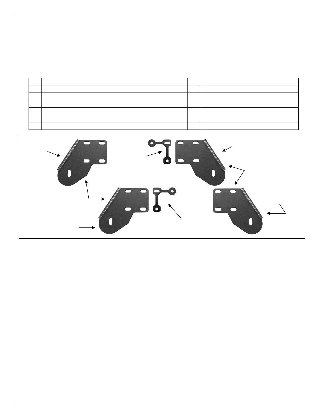
Driver/Left Rear
Mounting Bracket
Front Bracket to
Body Spacer
Driver/Left Front
Mounting Bracket
Same Bracket
Same Bracket
Passenger/Right
Rear Mounting
Bracket
Passenger/Right Front
Mounting Bracket
PROCEDURE:
1. REMOVE CONTENTS FROM BOX. VERIFY ALL PARTS ARE PRESENT. READ INSTRUCTIONS
CAREFULLY BEFORE STARTING INSTALLATION. ASSISTANCE IS RECOMMENDED.
2. Starting on the driver side-front of the vehicle, locate the front set of factory holes in the body panel and
the (2) holes in the pinch weld under the front of the front door, (Figures 1 & 2). Insert (1) 10mm Clip
Nut into the rectangular opening and line up the threaded hole in the Clip with the round hole next to
the opening. NOTE: Threaded nut must go towards the inside of the body panel, (Figures 1 & 2).
3. Next, select (1) Front Bracket Spacer and (1) Driver Side Front Bracket. Line up the (2) holes in the
Spacer with the Clip Nut and (1) hole in the pinch weld, (Figures 3 & 4). Insert (1) 10mm x 40mm Hex
Bolt, (1) 10mm Lock Washer and (1) 10mm Flat Washer through the top hole in the Bracket, the Spacer
and into the Clip Nut, (Figure 5). Leave hardware loose. Bolt the bottom of the Bracket to the pinch
weld and Spacer with the included (2) 10mm x 40mm Hex Bolts, (2) 10mm Lock Washers, (4) 10mm
Flat Washers and (2) 10mm Hex Nuts, (Figure 5). NOTE: Insert Hex Bolts in from the outside, through
the pinch weld and then the Bracket.
4. Move to the last mounting location at the rear of the cab. Repeat Steps 2 – 3 for Rear Mounting
Bracket installation, (Figures 6 & 7). NOTE: Each rear mounting location is made up of a rectangular
hole with a round hole on each side and two holes through pinch weld, (Figure 7).
5. With assistance, carefully place the Sidebar into position and attach it to the Mounting Brackets using
the included (2) 1/2" x 2" Hex Bolts, (2) 1/2" Lock Washers and (2) 1/2" Flat Washers, (Figures 5 & 8).
6. Level and align the Sidebar with the side of the vehicle then tighten all hardware.
7. Repeat Steps 2 – 6 for passenger side Mounting Bracket and Sidebar installation.
Front Bracket to
Body Spacer
Page 1 of 3 6/29/12 Rev3 (DP)
Page 3

90-DEGREE BENT END SIDEBAR
99-12 FORD F-250/450 SUPERDUTY REG, SUPER AND SUPER CREW CABS
8. Periodically check and retighten the hardware as necessary.
To protect your investment, wax this product after installing. Regular waxing is recommended to add a
protective layer over the finish. Do not use any type of polish or wax that may contain abrasives that could
damage the finish.
For stainless steel: Aluminum polish may be used to polish small scratches and scuffs on the finish. Mild
soap may be used also to clean the Sidebar.
For gloss black finishes: Mild soap may be used to clean the Sidebar.
Driver Side Installation Pictured
Front
Line up Clip Nut
with factory hole
Front
(Fig 1) Driver side front mounting location
Fig 2
Front
Back of pinch weld
Front
Disregard extra slot
on front bracket
installation
(Fig 3) Front Bracket Spacer on driver side
Spacer installs between the body
panel and front Bracket only
Fig 4
Page 2 of 3 6/29/12 Rev3 (DP)
Page 4

10mm Clip Nut
10mm x 40mm Hex Bolt
10mm Lock Washer
10mm Flat Washer
Fig 5
(2) 10mm x 40mm Hex Bolts
(2) 10mm Lock Washers
(4) 10mm Flat Washers
(2) 10mm Nuts
Rear
99-12 FORD F-250/450 SUPERDUTY REG, SUPER AND SUPER CREW CABS
Driver Side Installation Pictured
Disregard extra slot on front
bracket installation
Front
Line up 10mm Clip Nut
with factory holes
90-DEGREE BENT END SIDEBAR
Line up Clip Nuts
with factory holes
(Fig 6) Example of typical rear mounting location
Fig 7
(2) 10mm x 40mm Hex Bolts
(2) 10mm Lock Washers
(4) 10mm Flat Washers
(2) 10mm Nuts
1/2" x 2" Hex Bolts
1/2" Lock Washer
1/2" Flat Washer
Page 3 of 3 6/29/12 Rev3 (DP)
(2) Clip Nuts
(2) 10mm x 40mm Hex Bolts
(2) 10mm Lock Washers
(2) 10mm Flat Washers
Rear
Fig 8
 Loading...