

Page 1
12
07- CHEVY TRAVERSE/GMC ACADIA/07-10 SATURN OUTLOOK/07-09 BUICK ENCLAVE
(EXCL. 2010-11 BUICK ENCLAVE)
PARTS LIST:
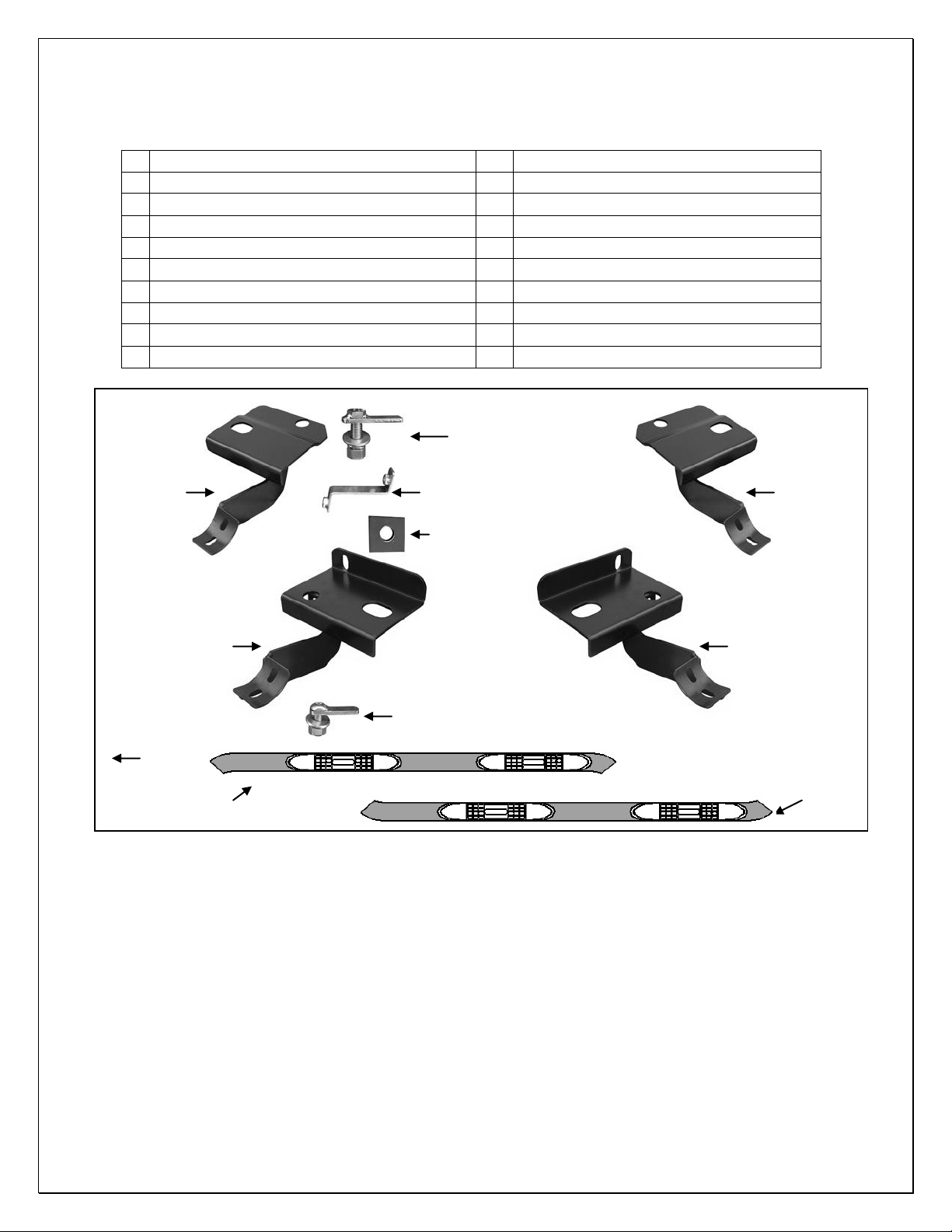
1 Driver/Left Sidebar 6 12mm Lock Washers
1 Passenger/Right Sidebar 6 12mm ID x 32mm OD x 3mm Flat Washers
1 Driver/Left Front Mounting Bracket 6 12mm Hex Nuts
1 Passenger/Right Front Mounting Bracket 4 10mm Lock Washers
1 Driver/Left Rear Mounting Bracket 4 10mm x 27mm OD x 3mm Flat Washers
1 Passenger/Right Rear Mounting Bracket 4 10mm Hex Nuts
2 “Z” Brackets W/Welded 8mm Hex Nuts 12 8-1.25mm x 25mm Hex Bolts
6 12-1.75mm x 45mm Bolt Plates 12 8mm Lock Washers
4 10-1.5mm x 35mm Button Head Bolt Plates 10 8mm ID x 24mm OD x 2mm Flat Washers
6 12mm Square Washers
Passenger/Right
Side Rear
Mounting
Bracket
(6) 12mm x 35mm
Bolt Plates
(2) "Z" Brackets
W/8mm Hex Nuts
(6) 12mm Square Washers
Driver/Left
Side Rear
Mounting
Bracket
Passenger/Right Side
Front Mounting
Bracket
Front
(4) 10mm Button Head Bolt
Plates (Use for installation on
2010-12 Vehicles Only)
-
Passenger/Right Sidebar
PROCEDURE:
1. REMOVE CONTENTS FROM BOX. VERIFY ALL PARTS ARE PRESENT. READ INSTRUCTIONS
CAREFULLY BEFORE STARTING INSTALLATION.
NOTE: The fatory may spray excess foam on the floor panel you may need to scrap foam away
from holes to allow bolt plates to fit into holes & work correctly.
2. Start installation on the passenger side and locate the factory holes in the bottom and side of the floor
panel towards the front of the vehicle.
3. Next, select (1) 8mm "Z" Bracket, (Figure 1B). Insert the end with the hex nut welded onto the outside
of the Bracket into the round hole in the bottom of the floor panel. Maneuver the "Z" Bracket through the
inside of the floor panel and line it up to the hole in the side of the floor panel, (Figures 1A, 2 & 6).
a. On 2007-09 Vehicles: There is an oval hole and a round hole on the bottom of the floor panel
and a round hole on the side of the floor panel. Insert (1) 12mm x 45mm Bolt Plate into the oval
hole and turn the Bolt Plate 90-degees so that the plate is across opening, (Figures 1 & 3B).
b. On 2010-11 Vehicles: There are two round holes on the bottom of the floor panel, (one
centered, one offset toward the pinch weld), and one round hole on the side of the floor panel.
Insert (1) 10mm x 35mm Button Head Bolt Plate into the round hole in the center of the floor
panel (Figures 2 & 4B). Make sure that the plate is supported across the hole in the floor panel.
Page 1 of 5
Driver/Left Side
Front Mounting
Bracket
Driver/Left Sidebar
Page 2

12
07- CHEVY TRAVERSE/GMC ACADIA/07-10 SATURN OUTLOOK/07-09 BUICK ENCLAVE
(EXCL. 2010-11 BUICK ENCLAVE)
4. Position the passenger side front Mounting Bracket up to the vehicle and over the previously installed
Bolt Plate and "Z" Bracket. NOTE: The hole pattern on the Mounting Bracket will match up with the hole
pattern on the floor panel. Bolt the Mounting Bracket to the Bolt Plate using the included hardware.
a. On 07-09 Vehicles: Use (1) 12mm Square Washer, (1) 12mm Lock Washer and (1) 12mm Hex
Nut to secure the Bracket to the Bolt Plate, (Figure 3A). Do not tighten hardware at this time.
b. On 2010- : Use (1) 12mm Square Washer, (1) 10mm Flat Washer, (1) 10mm Lock
12 Vehicles
Washer and (1) 10mm Hex Nut to secure the Bracket to the 10mm Bolt Plate, (Figure 4A). Do
not tighten hardware at this time.
5. Insert (1) 8mm x 25mm Hex Bolt, (1) 8mm Lock Washer, and (1) 8mm Flat Washer through the
Mounting Bracket, the side of the floor panel and into the nut on the "Z" Bracket, (Figures 3 & 4).
Attach the remaining end of the “Z” Bracket to the tab on the bottom of the Mounting Bracket using the
included (1) 8mm x 25mm Hex Bolt and (1) 8mm Lock Washer, (Figures 4 - 6). Snug but do not fully
tighten hardware at this time.
6. Move toward the rear of the vehicle and locate the round or oval hole centered in the bottom of the floor
panel as described in Step 2, (Figures 7 & 8).
a. 07-09 vehicles are equipped with an oval hole in the center of the floor panel as described in
Step 2a. Insert (1) 12mm x 45mm Bolt Plate into the oval hole in the center of the floor panel
and turn 90-degees across the oval hole, (Figure 7).
b. 2010- vehicles are equipped with a round hole in the center of the floor panel as described in
12
Step 2b. Insert (1) 10mm x 35mm Bolt Plate into the round hole in the center of the floor panel,
(Figure 8).
7. Next, locate the large hole slightly in toward the center of the vehicle from the previously installed Bolt
Plate. NOTE: Use the passenger side Rear Bracket to determine the correct mounting hole to use.
Insert (1) 12mm x 45mm Bolt Plate into the factory hole, (Figures 7 & 8). NOTE: Do not center the Bolt
Plate in the hole, the shorter end of the Bolt Plate should be pushed to one side of the factory hole in
order to fully engage.
8. Hold the passenger side Rear Mounting Bracket up to the vehicle and over the previously inserted Bolt
Plates. Secure Mounting Bracket to the Bolt Plates using the included hardware.
a. On 07-09 Vehicles: Use (1) 12mm Square Washer, (1) 12mm Lock Washer and (1) 12mm Hex
Nut to secure the Bracket to the Bolt Plate in the oval hole, (Figure 9). Use (1) 12mm Flat
Washer, (1) 12mm Lock Washer and (1) 12mm Hex Nut to secure the Bracket to the Bolt Plate
in the round hole. Do not tighten hardware at this time.
b. On 2010-11 Vehicles: Use (1) 12mm Square Washer, (1) 10mm Flat Washer, (1) 10mm Lock
Washer and (1) 10mm Hex Nut to secure the Bracket to the 10mm Bolt Plate in center of the
floor panel, (Figure 10). Use (1) 12mm Flat Washer, (1) 12mm Lock Washer and (1) 12mm Hex
Nut to secure the Bracket to the Bolt Plate in the round hole. Do not tighten hardware at this
time.
9. Carefully position the passenger Sidebar onto the Mounting Brackets. Bolt the Sidebar to the Mounting
Brackets with the included (4) 8mm x 25mm Hex Bolts, (4) 8mm Lock Washers and (4) 8mm Flat
Washers, (Figure 11).
10. Level and adjust the Sidebar properly and tighten all hardware at this time. IMPORTANT! Do not move
the Mounting Brackets too much when adjusting the Sidebar; this may cause Bolt Plates to disengage
from the factory holes.
11. Repeat Steps 2 – 10 for driver Sidebar installation.
12. Do periodic inspections to the installation to make sure that all hardware is secure and tight.
To protect your investment, wax this product after installing. Regular waxing is recommended to add a
protective layer over the finish. Do not use any type of polish or wax that may contain abrasives that could
damage the finish.
For stainless steel: Aluminum polish may be used to polish small scratches and scuffs on the finish. Mild
soap may be used also to clean the Sidebar.
For gloss black finishes: Mild soap may be used to clean the Sidebar.
Page 2 of 5
Page 3

12
07- CHEVY TRAVERSE/GMC ACADIA/07-10 SATURN OUTLOOK/07-09 BUICK ENCLAVE
Passenger Side Installation Pictured
Front
Line up "Z" Bracket
with this hole
12mm x 45mm Bolt Plate
(Fig 1A) 07-09 Model Pictured-Note Oval Hole
12mm x 45mm Bolt Plate
12mm Square Washer
12mm Lock Washer
12mm Hex Nut
8mm x 25mm Hex Bolt
8mm Lock Washer
8mm Flat Washer
Front
Fig 3A
Fig 4B Fig 3B
8mm "Z" Bracket
10mm x 35mm Bolt Plate
(Fig 2) 2010-11 Model Pictured-Note Round Hole
10mm x 35mm Bolt Plate
12mm Square Washer
10mm Flat Washer
10mm Lock Washer
10mm Hex Nut
Fig 4A
(EXCL. 2010-11 BUICK ENCLAVE)
Up
(Fig 1B) 8mm "Z" Bracket
Front
8mm "Z" Bracket
8mm x 25mm Hex Bolt
8mm Lock Washer
8mm Flat Washer
Front
Page 3 of 5
Page 4

07- CHEVY TRAVERSE/GMC ACADIA/07-10 SATURN OUTLOOK/07-09 BUICK ENCLAVE
Front
Fig 5
8mm x 25mm Hex Bolt
8mm Lock Washer
Rear
Fig 7
12
Passenger Side Installation Pictured
Tab with 8mm nut on
end of "Z" Bracket
Front
(Fig 6) Example of "Z" Bracket
12mm x 45mm Bolt Plate
Fig 8
10mm x 35mm Bolt Plate
installation-most of Bracket installs
inside body panel and is not visible
Rear
(EXCL. 2010-11 BUICK ENCLAVE)
12mm x 45mm Bolt Plate
Page 4 of 5
Page 5

12
07- CHEVY TRAVERSE/GMC ACADIA/07-10 SATURN OUTLOOK/07-09 BUICK ENCLAVE
(EXCL. 2010-11 BUICK ENCLAVE)
Passenger Side Installation Pictured
Rear
12mm x 45mm Bolt Plate
12mm Square Washer
12mm Lock Washer
12mm Hex Nut
10mm x 35mm Bolt Plate
12mm Square Washer
10mm Flat Washer
10mm Lock Washer
10mm Hex Nut
Rear
(Fig 9) 2007-09 Passenger Side
Rear Installation Pictured
8mm x 25mm Hex Bolt
8mm Lock Washer
8mm Flat Washer
Fig 11
12mm x 45mm Bolt Plate
12mm Square Washer
12mm Lock Washer
12mm Hex Nut
Fig 10
(Fig 10) 2010-11 Passenger Side
Rear Installation Pictured
Page 5 of 5
 Loading...