

Page 1
Qty
Description
Qty
Description
1
Grille Guard
12
12-1.75mm Hex Nuts
Upper Frame Mounting Brackets (for trucks
without tow hooks only)
1
Driver/Left Lower Frame Mounting Bracket
4
8mm x 22mm OD x 2mm Flat Washers
Passenger/Right Lower Frame Mounting
Bracket
1
Driver/Left Upper Support Bracket
2
5-.8mm x 15mm Button Head Allen Bolt
1
Passenger/Right Upper Support Bracket
4
5mm x 10mm OD x 1mm Flat Washers
1
Driver/Left Lower Support Bracket
2
5mm Nylon Lock Nuts
1
Passenger/Right Lower Support Bracket
1
Support flange
12-1.5mm x 30mm Special Fine Thread Hex
Bolt (for trucks without tow hooks only)
1
Wrench
2
8mm hex bolts
8
12-1.75mm x 35mm Hex Bolts
2
8mm Flat washers
22
12mm x 32mm OD x 3mm Flat Washers
2
8mm Lock washers
14
12mm Lock Washers
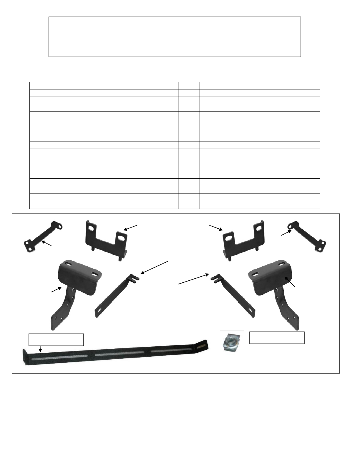
Passenger/
Bracket
Driver/Left
Bracket
Passenger/Right
Support Bracket
(2) Upper Frame Bracket
(will fit left or right)
Driver/Left Support Bracket (Support
Passenger/
Bracket
Driver/Left
Top Bracket
INSTALLATION INSTRUCTIONS
Support Flange
(2) 8mm Nut Clips
Page 1 of 7
PARTS LIST:
2009-13 DODGE RAM 2 & 4WD 1500
PART # P5058
2
1
2
Right Top
Right Lower
Mounting
PROCEDURE:
1. REMOVE CONTENTS FROM BOX. VERIFY ALL PARTS ARE PRESENT. READ INSTRUCTIONS
CAREFULLY BEFORE STARTING INSTALLATION. CUTTING IS REQUIRED. ASSISTANCE IS
RECOMMENDED.
10/30/2013
4 8mm x 20mm Button Head Allen Bolts
4 8mm Lock Washers
2 8mm Nut clips
Brackets pictured in position for
installation on tow hook equipped
vehicles. Reverse direction for vehicles
without tow hooks)
Lower
Mounting
Page 2

Page 2 of 7
2. Start by Selecting your LED light (Sold Separately) mounting hardware & brackets, you will need to first
attached the hardware to the support flange, (Example of LED light attached Fig 1) NOTE: if you have
your own LED light, LED Manufactures will have similar but different mounting styles or brackets,
once you determine you mounting options attach it to the support flange as seen in (Fig1)
3. With the LED light attached to the support flange select the (2) 8mm nut clips place each nut clip into the
slotted holes on either side of the support flange, as seen in (Fig 2) with the support flange prepare you will
need to lay the grill guard face down to install the support flange NOTE: (it is recommended to lay out
some of the cardboard your grill guard came in or a blanket to protect the grill guard finish). place the grill
guard face down with this done place the support flange with the LED attached into the Center flange
attach each side of the support flange to the inner brackets inside the center flange of the grill guard with
(2) 8mm hex bolts, (2) 8mm flat washers, & (2) 8mm lock washers as seen in (Fig 3) Snug but do not
tighten at this time.
4. Starting at the underside of the front bumper, carefully remove the plastic splash guard. NOTE: Depending
on the model of truck, the splash guard may be attached to the bottom of the truck with hex bolts and
several two-piece plastic push-in clips. Remove all hex bolts then locate the clips behind the bumper cover,
(Fig 4A). Pr y up on the center pin of the clip with a small flat blade screwdriver and remove the entire clip,
(Fig 4B). Pay close attention to the type and location of all factory hardware for reinstallation. The splash
guard may also be attached to the bumper cover with rivets at the corners. Use wire cutters to remove the
rivets. Once all fasteners have been removed, move splash guard to a clean stable work area.
5. Next, determine if the truck is equipped with tow hooks.
For models without tow hooks:
a. Remove the hex nuts from the two lower factory bumper bolts, (Fig 5).
b. Select (1) Frame Bracket, (will fit left or right-without tow hooks only), and the driver side Mounting
Bracket, (Fig 6). Bolt the two Brackets together with (2) 12mm Flat Washers, (2) 12mm Lock
Washers and (2) 12mm Hex Nuts. Snug the hardware but do not tighten at this time.
c. Insert the assembled Mounting Bracket up from behind the bumper and align the holes in the
Mounting Bracket with the bumper bolts. Attach the Bracket to the bumper bolts using the factory
hex nuts and snug but do not tighten the hardware, (Fig 7).
NOTE: O n some vehicles, it may be easier to assemble the two-piece bracket on the vehicle. Install the
Upper Frame Bracket first, then bolt the Lower Frame Bracket to the bottom as previously described.
d. Install the driver side Lower Support Bracket with the bent end toward the front of the vehicle,
(Figure 6). Bolt the Support Bracket to the inside of the Lower Mount using the top round hole in
the Lower Mounting Bracket with the included (1) 12mm x 35mm Hex Bolt, (2) 12mm Flat
Washers, (1) 12mm Lock Washer and (1) 12mm Hex Nut, (Figure 7).
e. Attach the flat end of the driver side Bracket to the frame with (1) 12-1.5mm x 30mm Special Fine
Thread Hex Bolt, (1) 12mm Flat Washer and (1) 12mm Lock Washer, (Fig 7). IMPORTANT: The
hole in the bottom of the frame is fine thread. Only use the 12-1.5mm x 30mm Hex Bolt provided
in the hardware kit. Snug but do not tighten all hardware at this time.
For models w ith tow hooks:
a. Remove the (2) hex nuts holding the front of the tow hook to the back of the bumper, (Fig 8).
b. Select the driver side Lower Mounting Bracket, (Fig 9). Hang the Bracket from the tow hook
mounting studs using the factory Hex Nuts, (Fig 10). Do not tighten hardware at this time.
c. Bolt the flat end of the driver side Support Bracket to the inside of the Lower Mounting Bracket
using the second round hole from the top, (Fig 9 & 11). Use the included (1) 12mm x 35mm Hex
Bolt, (2) 12mm Flat Washers, (1) 12mm Lock Washer and (1) 12mm Hex Nut.
d. Attach the bent end of the Support Bracket to the rear tow hook bolt. Loosen the rear mounting
bolt for the tow hook. Insert the slotted end under the head of the factory bolt, (Fig 11).
e. Snug but do not tighten all hardware at this time.
6. Repeat the appropriate Step 3 for the passenger side Mounting Bracket installation.
10/30/2013
Page 3

Page 3 of 7
7. Move to the top of the grille opening and open the hood, (Fig 12). Remove the driver side inner headlight
mounting screw. Insert the driver side Top Bracket between the radiator support and the headlight housing,
(Fig 13). Reinstall the factory hex bolt and snug but do not tighten at this time. Repeat this Step for the
passenger side Top Bracket installation.
8. With assistance, hold the Grille Guard up to the outside of the Mounting Brackets. Bolt the Grille Guard to
the Brackets with (6) 12mm x 35mm Hex Bolts, (12) 12mm Flat Washers, (6) 12mm Lock Washers and (6)
12mm Hex Nuts, (Fig 14). Do not tighten hardware at this time.
9. Line up the driver side Top Bracket with the (2) threaded inserts in the bottom of the headlight guard tube.
Bolt the Bracket to the inserts with (2) 8mm x 20mm Button Head Allen Bolts, (2) 8mm x 22mm x 1.5mm
Flat Washers and (2) 8mm Lock Washers, (Fig 15). Repeat this Step to attach the passenger side Top
Bracket. Do not tighten hardware at this time.
10. IMPORTANT: Slowly close the hood to check for clearance between the hood and the Top Brackets.
Adjust as necessary then snug but do not tighten the hardware.
11. Stand back from the vehicle and check to see that the Grille Guard is centered and level on the vehicle and
adjust as necessary. IMPORTANT: Once properly aligned, tighten only the hardware securing the lower
frame Mounting Brackets to the truck. Do not tighten the hardware on the Grille Guard.
12. Remove the Grille Guard but leave the lower Mounting Brackets on the vehicle.
13. Next, hold the splash guard up to the bumper cover and align it with the mounting points, (Fig 16). Mark
the location of the Mounting Brackets onto the back of the splash guard. Cut an approximately 1/2" wide by
4" long slot in the splash guard as pictured in Fig 17. NOTE: T he size of the slot is an estimate only and
may vary due to different factory designs for the splash guards and front bumper covers. Also, additional
cutting may be required to clear the Support Bracket on vehicles equipped with tow hooks. IMPORTANT:
To maintain the integrity of the splash guard, do not cut the slot any larger than necessary. Do not cut
through the front or back edges of the cover, (Fig 17). Make several small cuts first and check the fit often
for a clean installation.
14. Check the fit and reinstall the splash guard using the factory hardware. Use the included (2) 5mm x 15mm
Allen Bolts, (4) 5mm Flat Washers and (2) 5mm Lock Nuts to replace the rivets if required, (Fig 18).
15. Re-install, level and adjust the Grille Guard as described in Step 7. Tighten all hardware.
16. For the Led lights wiring please refer to the manufactures installation.
Do periodic inspections of the installation to make sure that all hardware is secure and tight.
To protect your investment, wax this product after installing. Regular waxing is recommended to add a
protective layer over the finish. Do not use any type of polish or wax that may contain abrasives that could
damage the finish.
10/30/2013
Page 4

Pry up the center pin to
(Fig 4A) Pictured from behind bumper
Fig 4B
Pin
Housing
For illustration only, clips
Fig 1
LED light attached to support flange.
8mm nut clip
Fig 2
Support flange
Secure support flange into center flange with
Per side.
Fig 3
Led Light
Page 4 of 7
attached (1) per side
Driver Side Installation Pictured
remove the complete fastener
NOTE:
but different mounting styles or brackets,
once you determine you mounting options
attach it to the support flange as seen.
(1) 8mm Hex head bolt
(1) 8mm Flat Washers
(1) 8mm Lock washer
LED Manufactures will have similar
may differ depending on
model and year
10/30/2013
Page 5

Driver Side Installation Pictured
IMPORTANT: For models without tow hooks,
(Fig 5) Driver side pictured from behind
Front
(Fig 8) Driver side mounting location pictured from
behind bumper on tow hook equipped model
Front
Fig 7
Front
Remove the (2) factory hex nuts
from the lower bumper bolts
Factory hex nuts
(2) 12mm Flat Washers
Remove the (2) factory
hex nuts from tow hook
(Fig 6) Driver side Brackets Pictured
(non tow hook models)
(Fig 9) Driver side Brackets
pictured (models with tow hooks)
Front
Front
Front
(Fig 10) Attach the driver side Frame
Mounting Bracket to the bottom of the tow
Installation pictured without the
splash guard for illustration
Reuse (2) factory
hex nuts
Driver/Left
Support Bracket
Driver/Left
Mounting Bracket
Driver/Left Frame Bracket
(no tow hook models)
Page 5 of 7
bumper (non tow hook models)
(2) 12mm Lock Washers
(2) 12mm Hex Nuts
only use the supplied
12-1.5mm x 30mm Fine Thread Hex Bolt
12mm Lock Washer
12mm Flat Washer
10/30/2013
Page 6

Driver Side Installation Pictured
Fig 11
(Fig 13) Insert tab on Top Bracket between
the headlight housing and radiator support
(3) 12mm x 35mm Hex Bolts
Fig 12
(2) 8mm x 20mm Button Head Bolt
(Fig 14) Rotate the Grille Guard up into position
Fig 15
Front
Front
Front
Front
Front
Installation pictured without the splash
Factory hex bolt
Remove factory
hex bolt
12mm x 35mm Hex Bolt
Reuse factory hex bolt
Page 6 of 7
(2) 12mm Flat Washers
12mm Lock Washer
12mm Hex Nut
guard for instruction purposes only
(6) 12mm Flat Washers
(3) 12mm Lock Washers
(3) 12mm Hex Nuts
(2) 8mm Lock Washers
(2) 8mm Flat Washers
10/30/2013
Page 7

Do not cut
Fig 17
If required, replace the rivet at the co rner
5mm Nylon Lock Nut
Fig 16
Fig 18
Front
Front
Hold the splash guard up to the
splash guard of the splash guard.
Complete Installation
Page 7 of 7
of the splash guard with the supplied:
5mm x 15mm Button Head Allen Bolt
(2) 5mm Flat Washers
Driver Side Installation Pictured
brackets and mark location for cutting
to clear brackets. Cut only what is
needed to insert bracket through the
through the front
or rear edge of the
splash guard
10/30/2013
 Loading...