

Page 1
PARTS LIST:
Qty Description Qty Description
1 Grille Guard 20 12mm x 24mm OD x 2.5mm Flat Washers
1 Driver/Left Frame Mounting Bracket 10 12-1.75mm Nylon Lock Nuts
1 Passenger/Right Frame Mounting Bracket 2 10-1.5mm x 30mm Button Head Bolts
1 Driver/Left Top Mounting Bracket 4 10mm x 20mm OD x 2mm Flat Washers
1 Passenger/Right Top Mounting Bracket 2 10mm Nylon Lock Nuts
2 8mm Special Rod Bolts 2 8mm x 28mm OD x 3mm Large Flat Washers
10 12-1.75mm x 30mm Hex Bolts 2 8mm Nylon Lock Nuts
2 8mm Clip nuts 2 8mm Button head bolts
2 8mm Flat washers 2 8mm lock washers
1 Support flange
INSTALLATION INSTRUCTIONS
2007-13 JEEP WRANGLER
PART# P1050
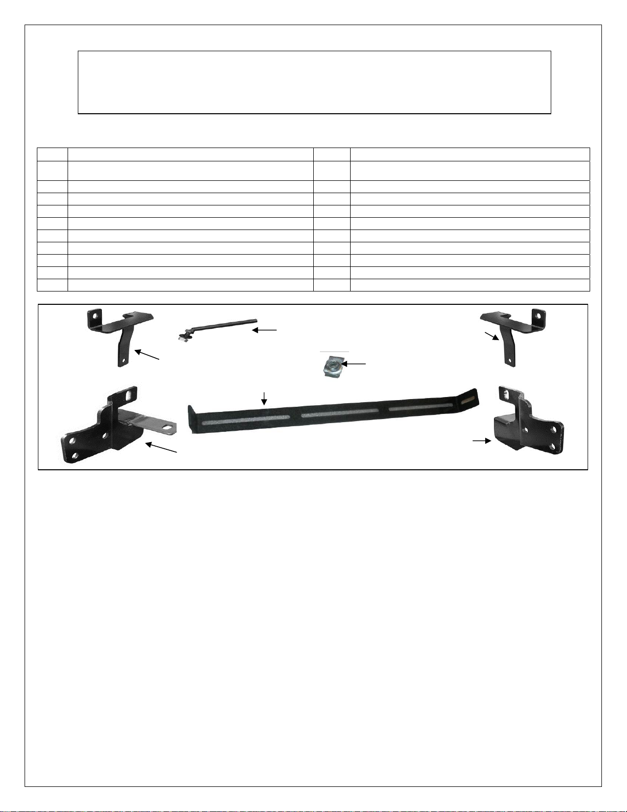
(2) 8mm Rod Bolts
Driver/Left Top
Mounting Bracket
Passenger/Right Top
Mounting Bracket
Support Flange
(2) 8mm Nut Clips
Passenger/Right Frame
Mounting Bracket
Driver/Left Frame
Mounting Bracket
PROCEDURE:
1. REMOVE CONTENTS FROM BOX. VERIFY ALL PARTS ARE PRESENT. READ INSTRUCTIONS
CAREFULLY BEFORE STARTING INSTALLATION. CUTTING IS REQUIRED. ASSISTANCE IS
RECOMMENDED.
2. Starting under the front bumper of the vehicle, remove the plastic top fill plate between the bumper
and the radiator. Also remove the lower factory splash guard. Place both on a clean, stable work
surface.
3. Select the passenger side Frame Mounting Bracket. Bolt the Frame Mounting Bracket to the
bottom of the cross member with (1) 12mm x 30mm Hex Bolt, (2) 12mm Flat Washers and (1)
12mm Nylon Lock Nut. NOTE: 07-09 models will use the outer mounting location (Fig 1A), and
2010-13 models will use the inner mounting location, (Fig 1B). Insert (1) 12mm x 30mm Hex Bolt,
(2) 12mm Flat Washers and (1) 12mm Nylon Lock Nut through the upper tab on the side of the
Mounting Bracket upright and tighten hardware at this time, (Fig 2). Repeat this step to install the
driver side Frame Bracket, (Fig 1C).
4. Next, place the top fill plate back in position and mark a slot on the underside straight up from the
frame upright, (the top brackets slide into the frame upright-see Fig 5). Cut (2) slots to clear the
Top Brackets, (Fig 3). NOTE: Only cut a slot large enough to clear the Top Mounting Brackets.
Page 2

IMPORTANT! Do not cut completely through front or rear edge of the fill panel. Reinstall the fill
panel with the factory hardware.
5. Next, slide the driver side Top Bracket down through the slot in the fill panel and into the frame
upright, (Fig 4). Select (1) 8mm Rod Bolt. Insert the Rod Bolt into the opening at the base of the
frame upright. Feed the Rod Bolt through the hole in the Top Bracket and out the frame upright
above the tab on the Frame Bracket, (Fig 5). Secure the Rod Bolt to the Top Mounting Bracket
with the included (1) 8mm Flat Washer and (1) 8mm Nylon Lock Nut, (Fig 6). Do not tighten
hardware at this time. NOTE: On 2012-13 vehicles, move the factory valve out of the way to
access the 8mm hardware on the driver side of the vehicle only. It is not necessary to remove of
disconnect the valve, (Fig 4, 6, 9).
6. Repeat Step 5 for the passenger side Top Mounting Bracket installation.
7. Hold the plastic lower splash guard up in its original position. Mark the location of the Mounting
Brackets onto the inside of the splash guard, (Fig 7). Cut out the sections to clear the Mounting
Brackets. Check for clearance, trim as required and reinstall using the factory hardware.
IMPORTANT: To maintain strength, remove as little material from the plastic splash guard as
possible. Do not cut completely through the front or rear edge of the splash guard.
8. Select your LED light (Sold Separately) with its mounting hardware & brackets so it may be
attached to the support flange, (Example of LED light attached) NOTE: if you have your own
LED light, LED Manufactures will have similar but different mounting styles or brackets,
once you determine you mounting options attach it to the support flange as seen in (Fig8)
9. Next select the (2) 8mm nut clips place each nut clip into the slotted holes on either side of the
support flange, as seen in (Fig 9) with the support flange prepare you will need to lay the grill
guard face down to install the support flange NOTE: (it is recommended to lay out some of the
cardboard your grill guard came in or a blanket to protect the grill guard finish). place the grill
guard face down with this done place the support flange with the LED attached into the Center
flange attach each side of the support flange to the upright plates of the grill guard with (2) 8mm
flat washers, & (2) 8mm button head bolts as seen in (Fig 10) Snug but do not tighten at this time.
10. With assistance, lift the Grille Guard up to the inside of the Frame Mounting Brackets. Line up the
holes in the Frame Mounting Brackets with the holes in the Grille Guard. Insert (6) 12-1.75mm x
30mm Hex Bolts, (12) 12mm Flat Washers and (6)12mm Nylon Lock Nuts, (Fig 11). Push the
grille guard back into an upright position. Secure the Top Brackets to the grille guard with the
included (2) 10mm x 30mm Button Head Allen Bolts, (4) 10mm Flat Washers and (2) 10mm Nylon
Lock Nuts, (Fig 12). Adjust the Brackets as necessary then snug but do not tighten all of the
hardware.
11. Stand back from the vehicle and check to see that the Grille Guard is centered and level on the
vehicle and adjust as required. It may be necessary to slightly loosen the Frame mounting
brackets to properly align the Grille Guard. IMPORTANT: Once properly aligned, tighten all of the
hardware.
12. With the grill guard now attached you may begin to align your LED light up or down once aligned
tighten the 8mm button head bolts on either side of the upright plates of the grill guard.
13. Now you may run your power wires for your LED light, Refer to the LED manufactures
recommendations on the installing of LED wiring harness.
Page 1 of 5
Page 3

14. Do periodic inspections of the installation to make sure that all hardware is secure and tight.
To protect your investment, wax this product after installing. Regular waxing is recommended to
add a protective layer over the finish. Do not use any type of polish or wax that may contain abrasives
that could damage the finish.
For stainless steel: Aluminum polish may be used to polish small scratches and scuffs on the finish.
Mild soap may be used also to clean the Grille Guard.
For gloss black finishes: Mild soap may be used to clean the Grille Guard.
Passenger Side Installation Pictured
12mm x 30mm Hex bolt
(2) 12mm Flat Washers
12mm Nylon Lock Nut
Front
12mm x 30mm Hex bolt
(2) 12mm Flat Washers
12mm Nylon Lock Nut
Front
Fig 1A
07-09 Passenger side Frame Mounting Bracket
bolts to the outer mounting location (pictured
with Grille Guard in position for example only)
Fig 1B
Front
2010-13 Passenger side Frame Mounting Bracket
bolts to the inner mounting location (pictured
with Grille Guard in position for example only)
2007-13 Driver side Frame Mounting
Bracket installation (pictured with Grille
Guard in position for example only)
Fig 1C
Page 2 of 5
Page 4

Driver Side Installation Pictured
Frame upright
Open end wrench
Front
Fig 2
12mm x 30mm Hex Bolt
(2) 12mm Flat Washers
12mm Nylon Lock Nut
Front
(Fig 4) Pictured without fill plate for example only
8mm Flat Washer
8mm Nylon Lock Nut
Front
(Fig 6) 2012 only: It may be a little easier to
install the 8mm hardware on Rod Bolt if you
temporarily move this factory valv e out of
the way-do not remove or disconnect
Front
Fig 3
Reinstall the fill panel and mark the cut area on the
bottom of the panel straight up from the frame upright.
Start with a small opening and slowly enlarge the
opening to get the best fit around the brackets. Area
cut from fill panel pictured for example only.
Insert Bracket into the
opening and bolt in place
with special Rod Bolt
Fig 5
Insert (1) 8mm Rod Bolt up
through opening in corner,
hole in Top Bracket and out
hole in side of frame upright
Page 3 of 5
Page 5

Fig 7
Fig 8
Fig 9
Front
Driver Side Installation Pictured
Once the Mounting Brackets have
been installed and checked for
alignment, hold the splash guard up
into position and mark the cut area
on the inside of the guard. Start with
a small opening and slowly enlarge
the opening to get the best fit around
the brackets. Area cut from guard
pictured for example only.
(Interior view)
LED light attached to support flange.
NOTE:
but different mounting styles or brackets,
once you determine you mounting options
attach it to the support flange as seen.
8mm nut clip
attached (1) per side
Secure support flange into
center flange with
(1) 8mm Button head bolt
(1) 8mm Flat Washers
(1) 8mm Lock washer
LED Manufactures will have similar
Fig 10
8mm nut clip
Support flange
Page 4 of 5
Page 6

Front
(3) 12mm x 30mm Hex Bolts
(6) 12mm Flat Washers
(3) 12mm Nylon Lock Nuts
(Fig 11) Pictured without splash guard for example
Installation complete
Front
(1) 10mm x 30mm Button
Head Allen Bolt
(2) 10mm Flat Washers
(1) 10mm Nylon Lock Nut
(Fig 12) Pictured without fill plate for example
Page 5 of 5
 Loading...