

Page 1
INSTALLATION INSTRUCTIONS
p
p
r
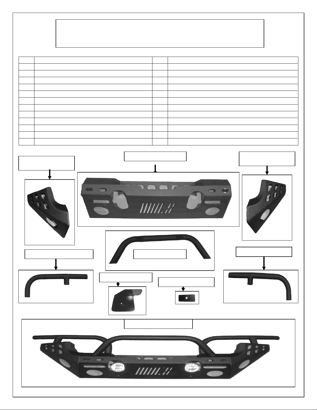
2007-12 WRANGLER FRONT REPLACEMENT BUMPER
PART # AL15600-3
PARTS LIST:
Qty Description Qty Description
1 Bumper Center section 8 12mm Nuts
1 Bumper Corner Passenger/right side 18 10mm x 35mm Hex bolts
1 Bumper Corner Driver/left side 30 10mm x 24mm OD Flat washers
1 Bumper Center section tube 18 10mm Lock washers
1 Bumper Corner tube Passenger/right side 12 10mm Nuts
1 Bumper Corner tube Driver/left side 6 4mm Socket cap screws
8 12mm x 35 mm Hex bolts 6 4mm lock nuts
16 12mm x 24mm OD Flat washers 12 4.25mm ID x 9mm OD Flat washers
1 Air pump Support bracket
14 12mm Lock washers 1 Air pump Support bracket plate
1 8mm x 25mm hex bolt 1 6mm x 35mm Hex Bolt
1 8mm lock washer 1 6mm Hex nut
Passenger/right side
Bum
er Corner
Bumper Center section
Passenger/right side tube
Center section tube
Driver/Left side tube
Support bracket
Support bracket plate
Front Bumper assembled
Driver/Left side
Bum
er Corne
Page 1 of 5
Page 2

PROCEDURE:
1. REMOVE CONTENTS FROM BOX. VERIFY ALL PARTS ARE PRESENT. READ
INSTRUCTIONS CAREFULLY BEFORE STARTING INSTALLATION.
Start by removing front plastic skid shield from under the vehicle, using a flat tip screwdriver pry
2.
and remove the plastic push pins holding the skid shield, seen in (Fig 1 & 1A)
3. Once removed start to remove the top plastic cover there are 2 push pins holding the plastic cover
in front of the grill, as seen in (Fig 2) with the plastic push pins removed, slide the cover to the left
side to allow for access of the inner nuts holding the bumper onto vehicle, as seen in (Fig 3 & 3A),
once done continue to remove driver side by sliding plastic to the right side (Fig 4 & 4A) shows
location of nuts to be removed.
4. Once inner nuts are removed begin to unplug the road lights from the factory wire harness, and
unclip the harness from the bumper cover, as seen in (Fig 5) once done, remove the outer nuts
holding the bumper onto the vehicles frame. as seen in (Fig 5A & 5B)
5. With the bumper removed, Select the Passenger & driver side bumper corners and mount each
side to the center section, with the supplied (12) 10mm hex bolts, (24) 10mm flat washers, (12)
10mm lock washers & (12) 10mm nuts as seen in (Fig 6 & 6A) Snug fasteners as you go along
once all fasteners are secure and your happy with the alignment tighten hardware.
6. Once corners are assembled to the center section, begin to install the upper tubes secure the right
& left sides with the (4) 10mm hex bolts, (4) 10mm x flat washers and (4) 10mm lock washers,
secure the center section tube with the (2) 10mm hex bolts, (2) 10mm x 24mm flat washers and
(2) 10mm lock washers as seen in (Fig 6 & 6A) align & tighten all hardware.
7. Next remove the factory road lights from the factory bumper and begin to install them into the new
bumper with the (3) 4mm Socket cap screws, (6) 4.25mm flat washers & (3) 4mm lock nuts per
side as seen in (Fig 7) align & tighten all hardware.
8. NOTE: 2007-2011 MODELS With help, position the new bumper up and over the factory
mounting points & secure the new bumper with (3) 12mm Hex bolts, (6) 12mm x 24mm OD flat
washers, (3) 12mm lock washers & (3) 12mm nuts per side, NOTE: pending on the year of the
vehicle only 3 of the 4 bolts per side will line up when mounting to the factory bumper brackets, as
seen in (Fig 8) Snug but do not tighten hardware, Plug in the road lights with the wire harness and
secure harness to bumper.
9. NOTE: FOR 2012 MODELS; With the factory bumper removed you will see the air pump on the
drivers side front of frame horn (Fig 9 shows location) remove the (2) factory nuts securing it to
frame bracket, once removed slip it off the factory studs and temporally move it just off to the side,
next with a set of pliers locate the (1) factory stud and bend it back & forth till it breaks off as seen
in (Fig 9A). Place the air pump back on the one stud as it came off and secure the one side with
the factory nut as seen in (Fig 9B). With help, position the new bumper up and over the factory
mounting points & secure the new bumper with (3) 12mm Hex bolts, (6) 12mm x 24mm OD flat
washers, (3) 12mm lock washers & (3) 12mm nuts per side, NOTE: pending on the year of the
vehicle only 3 of the 4 bolts per side will line up when mounting to the factory bumper brackets, as
seen in (Fig 8) Snug but do not tighten hardware, Plug in the road lights with the wire harness and
secure harness to bumper.
Page 2 of 5
Page 3

p
10. Next select the air pump support bracket and air pump support bracket plate, place the support
bracket in from under & behind the bumper and secure it with the support plate to the bumper
using the 8mm hex bolt & lock washer snug but do not tighten as seen in (Fig 10 & 10A) with the
bracket attached to bumper secure the air pump to the bracket with the 6mm hardware Snug but
do not tighten as seen in (Fig 11)
11. Level and adjust the bumper and tighten all hardware.
12. Do periodic inspections to the installation to make sure that all hardware is secure and tight.
To protect your investment, wax this product after installing. Regular waxing is recommended to
add a protective layer over the finish. Do not use any type of polish or wax that may contain abrasives
that could damage the finish.
For stainless steel: Aluminum polish may be used to polish small scratches and scuffs on the finish.
Mild soap may be used also to clean the Product.
For gloss black finishes: Mild soap may be used to clean the Product.
Fig 1
Fig 1A
Passenger/right side shown
Remove push pins
holding plastic skid
shield
Remove push pin holding
lastic skid shield
Fig 2
Fig 3
Plastic insert removed
Location of 2 factory nuts
holding front bumper
passenger side shown
Remove plastic insert
Fig 3A
Fig 4
Location of 2 factory nuts
holding front bumper driver
side shown
Page 3 of 5
Remove 2 factory nuts
holding front bumper
passenger side shown
Driver/left side shown
Page 4

(2)
Fig 4A Fig 5
Remove 2 factory nuts
holding front bumper
driver side shown
Fig 5A Fig 5B
Remove 2 factory nuts
holding front bumper
driver side shown
Fig 6 Fig 6A
Secure tube with
(2)10mm bolts
(2)10mm flat washers
(2)10mm lock washers
Secure corner to center
section with
(12)10mm bolts
(24)10mm flat washers
(12)10mm lock washers
(12)10mm nuts
Fig 7
Secure top bar to center section with
10mm Hex Bolts (2) 10mm flat washers (2) 10mm Lock washers
Secure road lights to center
section with
(3) 4mm Socket cap screws
(3) 4mm Lock nuts
(6) 4.25mm flat washers
Per side
Unplug wire
harness from lights
and unclip harness
from bumper
Remove 2 factory nuts
holding front bumper
passenger side shown
Secure tube with
(2)10mm bolts
(2)10mm flat washers
(2)10mm lock washers
Page 4 of 5
Page 5

Secure bumper per
side with
(3)12mm hex bolts
(6)12mm flat washers
(3)12mm lock washers
(3)12mm Nuts
Fig 9 Fig 8
Remove 2 factory nuts
holding air pump to
driver side frame rail
Fig 9A
Remove factory stud
by bending it back and
forth
Fig 10 Fig 10A
Inside bumper view
Secure to bumper with
8mm hardware
Fig 9B
Secure to
bracket with
Factory nut
Secure to bumper with
8mm hardware front view
Fig 11
Secure pump to
bracket with
6mm hardware
Page 5 of 5
Installation complete
 Loading...