

Page 1
INSTALLATION INSTRUCTIONS
2007-10 GMC ACADIA / 2007 09 CHEVY TRAVERSE
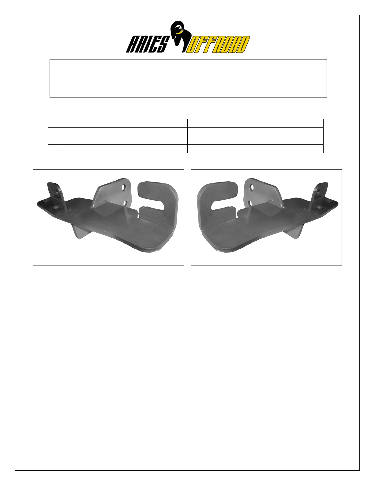
SPORT BAR PART #4550
PARTS LIST:
1 Sport Bar 6 12-1.75mm x 30mm Hex Head Bolts
1 Driver/Left Mounting Bracket 6 12mm Nylock Nuts
1 Passenger/Right Mounting Bracket 12 12mm ID x 29mm OD x 3mm Flat Washers
2 3/8” x 1” Self Tapping Bolts
PROCEDURE:
1. REMOVE CONTENTS FROM BOX. VERIFY ALL PARTS ARE PRESENT. READ INSTRUCTIONS
CAREFULLY BEFORE STARTING INSTALLATION. CUTTING REQUIRE D
2. Measure from the driver outer edge of the air dam 23” towa rds the inside of the car and mark the location. Use a
hack saw to cut a 1” x 3 ½” gap on the air dam (Figure 1). NOTE: Use the mark as center of the cutting location.
3. Remove the driver side factory hex nut located on the cross member bar. This is the hex nut that mounts the
radiator support (Figure 2).
4. Locate the driver side motor mount bushing. Use a 15mm socket to remove the two front (small) bolts. Proceed to
loosen up the rear (large) bolt just enough so you can slide the Mounting Bracket in between motor mount support
and frame (Figure 2).
5. Slide the slotted opening on the Mounting Bracket around the radiator support bolt and between radiator bracket
and frame, while you slide the Mounting Bracket between motor mount bushing (Figure 3).
6. Once the Mounting Bracket is in place, use the included 3/8” x 1” Self Tapping B olt to attach the outer front facing
Mounting Location on the Bracket to the factory hole on the cross member bar. Re-install the factory hex nut and
the two bolts removed from the motor mount bushing. Tighten all hardware at this time including the large bolt on
the motor mount bushing and frame (figure 4). Tighten large motor mount bolt to 75 ft lbs.
7. Repeat steps 2 – 6 for passenger side Mounting Bracket.
8. With help position the Sport Bar on the outer side of Mounting Brackets. Attach Sport Bar to Mounting Brackets
using the included (6) 12mm x 30mm Hex Head Bolts, (6) 12mm Nylock Nuts, and (12) 12mm Flat Washers
(Figure 5).
9. Level and adjust Sport Bar properly; and then tighten all hardware at this time.
10. Do periodic inspections to the installation to make sure that all hardware is secure and tight.
Page 2
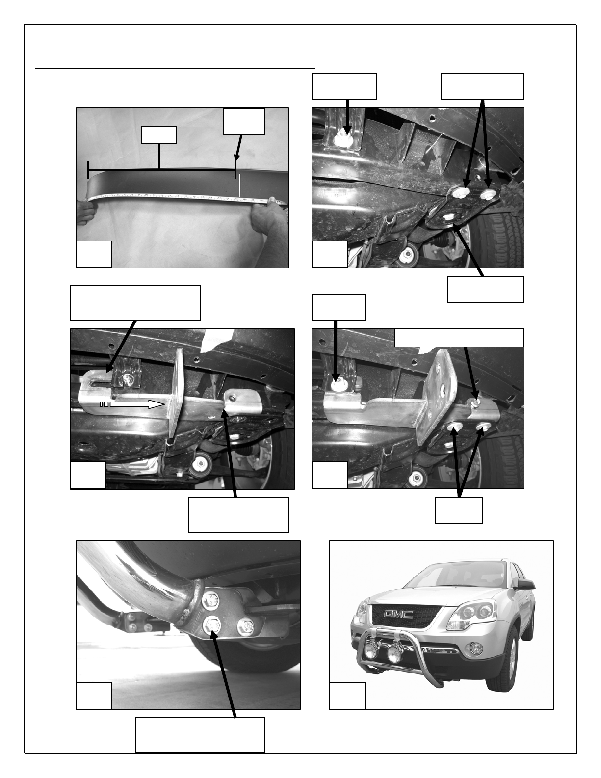
(Driver Side Mounting Bracket Installation Shown)
23”
Cut an 1”
slot here
Fig 1 Fig 2
Slide Mounting Bracket
between cross member bar
and radiator support bracket
Fig 3 Fig 4
Slide Mounting
Bracket between
motor mount bushing
Fig 5 Fig 6
12mm x 30mm Hex Head Bolts
12mm Nylock Nuts
12mm Flat Washers
Remove this
factory nut
Factory
hex nut
Remove these
two factory bolts
Loosen up this
factory bolt
3/8” x 1” Self Tapping Bolt
Factory
bolts
 Loading...