

Page 1
INSTALLATION INSTRUCTIONS
2010-12 1500 SILVERADO/SIERRA REG CAB (Short Box)
PART NUMBER 364020/364020-2
PARTS LIST:
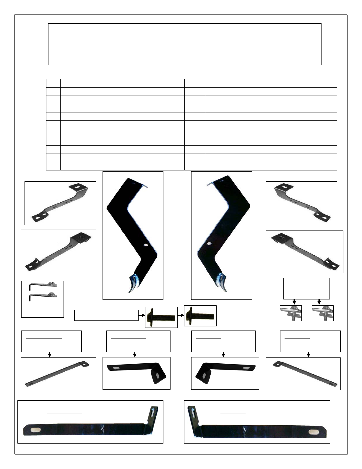
1 Passenger Side Bar 1 Driver Side Middle Support Bracket
1 Driver Side Bar 1 Passenger Side Rear Support Bracket
1 Passenger Side Front Mounting Bracket 1 Driver Side Rear Support Bracket
1 Driver Side Front Mounting Bracket 2 9mm ID x M38 x 38 Square Plastic Retainers
1 Passenger Side Center Mounting Bracket 2 10-1.5mm x 40mm T bolt (14mm W x 30mm L)
1 Driver Side Center Mounting Bracket 20 10-1.50mm x 30mm Hex Head Bolts
1 Passenger Side Rear Mounting Bracket 10 10mm Hex Nuts
1 Driver Side Rear Mounting Bracket 24 10mm Lock Washers
1 Passenger Side Front Support Bracket 30 10mm ID x 22mm OD x 1.5mm Flat Washers
1 Driver Side Front Support Bracket 2 10mm Nut Plates
1 Passenger Side Middle Support Bracket 2 10mm x 40mm Bolt Tabs
Passenger Side
Center Bracket
Passenger Side
Front Bracket
Passenger Side
Rear Bracket
10mm Nut Plates
10mm x 40mm T Bolts
Passenger Side
Front Support Bracket
Passenger Side
Middle Support Bracket
Passenger Side
Rear Support Bracket
Driver Side
Rear Bracket
Driver Side
Middle Support Bracket
Driver Side
Rear Support Bracket
Driver Side
Center Bracket
Driver Side
Front Bracket
10mm x 40mm Bolt
Plate (with Plastic
retainer installed)
Driver Side
Front Support Bracket
12/15/2011 Page 1 of 4
Page 2

PROCEDURE:
1. REMOVE CONTENTS FROM BOX. VERIFY ALL PARTS ARE PRESENT. READ INSTRUCTIONS
CAREFULLY BEFORE STARTING INSTALLATION.
2. From underside of vehicle remove front, and middle body mount bolts. Do not remove bushings. Hang
driver side front, and middle Mounting Brackets into position by partially threading factory body
mounting bolts back into body mounts (Fig 1) Snug but do not tighten at this time.
3. Locate the two factory holes in the bottom of the frame towards the front of the vehicle. Insert (1) Nut
Plate through oval hole and orient Nut Plate towards the front round hole, (Fig 2).
4. Attach driver side front Support Bracket to already inserted Nut Plate by partially threading (1) 10mm x
30mm Hex Head Bolt, (1) 10mm Lock washer, and (1) 10mm Flat Washer as seen in (Fig 3) Snug but
do not tighten at this time. Attach opposite side of driver side front Support Bracket to outside hole in
the Mounting Bracket using the included (1) 10mm x 30mm Hex Head Bolt, (1) 10mm Hex Nut, (1)
10mm Lock Washer, and (2) 10mm Flat Washers as seen (Fig 3). Snug but do not tighten at this time.
5. With the middle mounting bracket installed located just above the mount bracket there is a oblong hole
as seen in (Fig 4) place the T bolt in the hole turn it so it stays in place, select the driver side brace
bracket and secure it to the T bolt with (1) 10mm Hex Nut, (1) 10mm Lock Washer, and (1) 10mm Flat
Washers attach opposite side of driver side middle Support Bracket to inside hole in the Mounting
Bracket using the included (1) 10mm x 30mm Hex Head Bolt, (1) 10mm Hex Nut, (1) 10mm Lock
Washer, and (2) 10mm Flat Washers (Fig 4A). Snug but do not tighten at this time
6. With the drivers side front & middle mount brackets installed begin to install the drivers rear mount
brackets first by threading a Plastic Retainer onto the threaded end of a Bolt Plate; Insert the Bolt Plate
into the factory hole in frame rail location of hole in frame (Fig 5). Once the Bolt Plate is inserted, hold
the Bolt end with one hand and tighten the Plastic Retainer with your other hand, NOTE: Tighten the
Plastic Retainer until it reaches the side panel. (Fig 5A) Shows Bolt Plate installed with plastic retainer
next select the mount bracket and place it up and over the bolt tab, secure it with the (1)10mm washer,
(1) 10mm lock washer and (1) 10mm nut as seen in (Fig 6) Snug but do not tighten at this time.
7. Next with the drivers rear mounting bracket installed select the drivers rear support bracket remove the
factory bolt holding the box to the frame secure the support bracket with the factory bolt Snug but do
not tighten at this time, as seen in (Fig 7) secure the other end of the brace bracket to the mounting
bracket with the (1) 10mm x 30mm hex bolt (2) 10mm flat washer and (1) 10mm lock washer and (1)
10mm nut. (Fig 7A) shows bracket attached, Snug but do not tighten hardware at this time.
8. Carefully position Driver Side Bar onto Mounting Brackets. Attach Side Bar to Mounting Brackets using
the included (6) 10-1.50mm x 30mm Hex Head Bolts, (6) 10mm Lock Washers, and (6) 10mm Flat
Washers (Fig 8). Do not tighten at this time.
9. Level and adjust Side Bar, then tighten all hardware at this time.
10. Repeat steps 2-8 for passenger side bar
11. Do periodic inspections to the installation to make sure that all hardware is secure and tight.
12/15/2011 Page 2 of 4
Page 3

To protect your investment, wax this product after installing. Regular waxing is recommended to add a
protective layer over the finish. Do not use any type of polish or wax that may contain abrasives that could
damage the finish.
For stainless steel: Aluminum polish may be used to polish small scratches and scuffs on the finish. Mild
soap may be used also to clean the Products.
For gloss black finishes: Mild soap may be used to clean the Products.
Driver Side Installation Pictured
Fig 1 Fig 2
Front of Vehicle
Factory Bolt
Driver Side Front
Bracket Pictured
Front of Vehicle
Fig 3
10mm Nut Plate
10mm x 30mm Hex bolt
10mm Lock Washer
10mm Flat Washer
Fig 4
10mm x 30mm Hex bolt,
10mm Hex nut
10mm Flat Washers
10mm Lock Washer
Place 10mm T
Bolt in hole.
Fig 4A
Fig 5
10mm T Bolt
10mm Flat Washers
10mm Lock Washer
10mm Nut
Location for
10mm Bolt Plate.
10mm x 30mm Hex bolt,
10mm Hex nut
10mm Flat Washers
10mm Lock Washer
12/15/2011 Page 3 of 4
Page 4

Fig 5A Fig 6
Bolt tab in place
Fig 7 Fig 7A
Factory Bolt
Factory Bolt
Driver side Rear
support bracket
installed
Fig 8
Driver side Rear mount
bracket installed
10mm T Bolt
10mm Flat Washers
10mm Lock Washer
10mm Nut
Bolt tab
Driver side Rear mount
bracket installed
10mm x 30mm Hex bolt,
10mm Lock Washer
10mm Flat Washer
12/15/2011 Page 4 of 4
Page 5

INSTALLTION ALERT
General Motors has made changes to their late model 2010 and 20 12 Chevrolet Silverado and
GMC Sierra Light Duty and Heavy Duty Trucks and these changes affect the installation of our
Side Bars.
Currently, all Side Bars manufactured for GM trucks use the factory body mount bolts to attach
the bars and brackets to the truck. In years past, GM used a fixed nut that was welded in place to
the chassis of the truck. Starting late 2010, GM has now gone to a loose nut that is surrounded by
a "Cage Nut" which has two tabs on either side of the nut to keep it from loosening. Along with
this cage nut, GM is also using Heavy Duty Loc-tite on the Body Mount Bolts for added
protection.
Due to this change, Aries is recommending EXTREME CARE when removing the factory body
mount bolts from these trucks. Loosen and re-tighten all body mount bolts by hand! DO NOT
use Impact Tools of any kind! If bolts become increasingly tight as you are loosening them you
may need to retighten & loosen the bolt several times to clear the loc-tite from the threads Failure
to follow this instruction could cause the body mount bolts to seize and the tabs of the 'Cage Nut'
to bend allowing the nut to spin freely inside Chassis floor board!
Most of clients have been installing the existing side bar applications on these new trucks with no
issues, but please be sure to follow our recommendation to prevent any installation issues. If you
have any questions, please feel free to call our Customer Service Department at 888-800-2743.
Example of the General Motors Body Bolts
 Loading...