

Aries Automotive 224009-2 User Manual
INSTALLATION INSTRUCTIONS
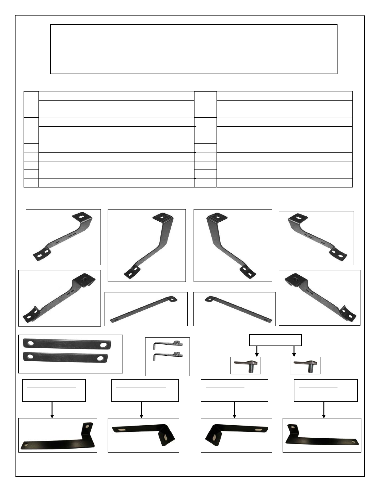
1999-13 1500-2500-3500 SILVERADO/SIERRA EXT CAB
PART NUMBER 224009/224009-2
PARTS LIST:
1 Passenger Side Bar 2
1 Driver Side Bar 2 10mm x 47mm bolt tab
1 Passenger Side Front Mounting Bracket 18 10-1.50mm x 30mm Hex Head Bolts
1 Driver Side Front Mounting Bracket 6 10mm Hex Nuts
1 Passenger Side Center Mounting Bracket 20 10mm Lock Washers
1 Driver Side Center Mounting Bracket 24 10mm ID x 22mm OD x 1.5mm Flat Washers
1 Passenger Side Rear Mounting Bracket 2 10mm Nut Plates
1 Driver Side Rear Mounting Bracket 2 12-1.75mm x 30mm Hex Head Bolts
Front Support Bracket 99-13 1500 (99-10 2500/3500)
2 2 12mm Hex Nuts
Center Support Brackets 99-13 1500 (99-10 2500/3500)
2 4 12mm ID x 29mm x 3mm Flat Washers
2 2 12mm Lock Washers
Front Support Bracket 2011-13 (2500/3500)
Passenger Side
Center Bracket
Passenger Side
Rear Bracket
Pass
enger Side
Front Support Bracket Front Support Bracket
Dri
Rear Bracket
Driver Side
Center Support Brackets
Passenger Side
Front Bracket
99-13 1500 / 99-10 2500/3500
99-13 1500 / 99-10 2500/3500
99-13 1500 (99-10 2500/3500)
2011-13 Passenger Side
Front Support Bracket
2500/3500 Models
2011-13 Passenger Side
Middle Support Bracket
10mm Nut Plates
odels
Center Support Brackets 2011-13 (2500/3500)
Dri
ver Side
Center Bracket
ver Side
Driver Side
Front Bracket
10mm Bolt tabs
2011-13 Driver Side
Middle Support Bracket
2500/3500 Models
2011-13 Driver Side
Front Support Bracket
2500/3500 Models 2500/3500 M
11/21`/2012
Page 1 of 5
11/21`/2012

PROCEDURE:
1. REMOVE CONTENTS FROM BOX. VERIFY ALL PARTS ARE PRESENT. READ INSTRUCTIONS
CAREFULLY BEFORE STARTING INSTALLATION.
2. From underside of vehicle remove front, center, and rear body mount bolts. Do not remove bushings.
3. Hang driver side front, center and rear Mounting Brackets into position by partially threading factory
body mounting bolts back into body mounts (Fig 1).
4. Locate the two factory holes in the bottom of the frame towards the front of the vehicle. Insert (1) Nut
Plate trough oval hole and orient Nut Plate towards the front round hole, (Fig 2).
5. Attach driver side front Support Bracket to already inserted Nut Plate by partially threading (1) 10mm x
30mm Hex Head Bolt, (1) 10mm Lock washer, and (1) 10mm Flat Washer (Fig 3 & 4).
(1999-13) Front brace brackets 1500 Models:
Attach opposite side of driver side front Support Bracket to outside hole in the Mounting Bracket using
the included (1) 10mm x 30mm Hex Head Bolt, (1) 10mm Hex Nut, (1) 10mm Lock Washer, and (2)
10mm Flat Washers (Fig 3). Do not tighten at this time.
(1999-10) Front brace brackets 2500 Models:
Note that the Support Bracket will not reach the Mounting Bracket (Fig 4). Tighten the Support Bracket
to Nut Plate in the frame. Carefully push up on the Support Bracket until it reaches the inside hole in the
Mounting Bracket (Fig 5). Attach opposite side of driver side front Support Bracket to inside hole in the
Mounting Bracket using the included (1) 10mm x 30mm Hex Head Bolt, (1) 10mm Hex Nut, (1) 10mm
Lock Washer, and (2) 10mm Flat Washers (Fig 6). Do not tighten at this time.
(2011-13) Front brace brackets 2500/3500 Models:
Attach driver side front Support Bracket to the already inserted Nut Plate by partially threading (1)
10mm x 30mm Hex Bolt, (1) 10mm Lock washer, and (1) 10mm Flat Washer as seen in (Fig 7)
Attach opposite side of driver side front Support Bracket to outside hole in the Mounting Bracket using
the included (1) 10mm x 30mm Hex Head Bolt, (1) 10mm Hex Nut, (1) 10mm Lock Washer, and (2)
10mm Flat Washers (Fig 7A). Do not tighten at this time.
(1999-11) 1500 and (1999-10) 2500 Models Middle brace brackets
6. From the inner side of the center body mount, place (1) Center Support Bracket onto front side of the
body mount. Attach Center Support Bracket to body mount using the included (1) 12-1.75mm x 30mm
Hex Head Bolt, (1) 12mm Hex Nut, (1) 12mm Lock Washer, and (2) 12mm Flat Washers (Fig 8 & 9).
Do not tighten at this time. NOTE: Larger hole on the Center Support Bracket mounts to body mount.
7. Attach opposite side of Center Support Bracket to center Mounting Bracket using the included (1) 10-
1.50mm x 30mm Hex Head Bolts, (1) 10mm Hex Nuts, (1) 10mm Lock Washers, and (2) 10mm Flat
Washers (Fig 8 & 9). Do not tighten at this time.
(2011-13) 2500 Models: Middle brace brackets
8.
Located just above the mount bracket there is a oblong hole as seen in (Fig 10) place the bolt tab in the
hole, select the driver side brace bracket and secure it to the bolt tab with (1) 10mm Hex Nut, (1) 10mm
Lock Washer, and (1) 10mm Flat Washers attach opposite side of driver side middle Support Bracket to
inside hole in the Mounting Bracket using the included (1) 10mm x 30mm Hex Head Bolt, (1) 10mm
Hex Nut, (1) 10mm Lock Washer, and (2) 10mm Flat Washers (Fig 10A). Do not tighten at this time.
9. Carefully position Driver Side Bar onto Mounting Brackets. Attach Side Bar to Mounting Brackets using
the included (6) 10-1.50mm x 30mm Hex Head Bolts, (6) 10mm Lock Washers, and (6) 10mm Flat
Washers (Fig 11). Do not tighten at this time.
10. Level and adjust Side Bar, then tighten all hardware at this time.
11. Repeat steps 2-9 for passenger Side Bar.
12. Do periodic inspections to the installation to make sure that all hardware is secure and tight.
Page 2 of 5
11/21`/2012
 Loading...