

Page 1
P
O
i
sTop
T
c
e
e
s
e
s
e
s
T
e
h
e
B
5
O
s
u
e
s
a
I
B
e
e
o
F
e
n
A
e
e
s
t
e
1Was
t
m
m
m
m
I
G
A
D
14 1
1
84 84 84 14 1
6
S
o
F
r
s
o
N
U
T
/
n
m
N
W
m
i
i
0
a
m
s
e
U
k
2
N
m
m
i
e
/
N
o
a
h
t
r
e
s
Pa
IMP
To t
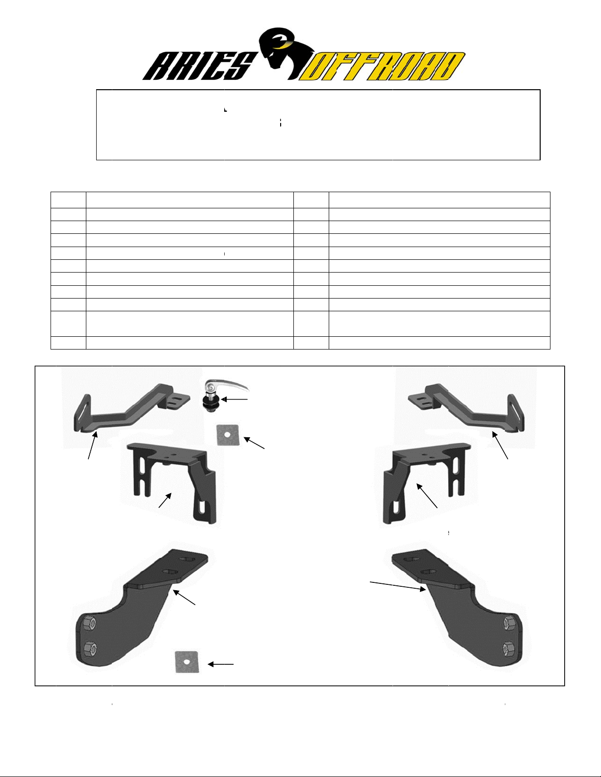
ARTS LIS
Qty Des
1 Grill
1 Driv
1 Pas
1 Driv
1 Pas
1 Driv
1 Pas
4 12-1
4 12m
4 12m
senger/Rig
Bracket
Pa
To
RTANT:
lt the Grill
:
ription
Guard
r/left Fram
enger/right
r/left Top F
enger/right
r/left Top
enger/right
.75mm x 3
m x 32mm
m Lock Wa
t
senger/Rig
p Frame Br
he Grille G
Guard, th
NST
Mounting
Frame Mou
rame Brack
Top Frame
racket
Top Brack
mm Hex B
D x 3mm
hers
ht
cket
Pass
Mou
ard is des
Quick Rel
LLAT
07-14
P
racket
nting Brack
t
Bracket
t
lts
lat Washer
(2) 10
(2) 10
(4) 10
(2) 10
(4)
nger/Right
ting Bracke
(4) 12mm
igned to til
ase Bolts
ON I
RILLE G
TOYOTA
RT # 2067
Qty
2
t 2
4
2
m Quick R
m Special
m Flat Wa
m Nylon L
0mm Plasti
hers
Driver/Left
Mounting B
Frame
Plastic Was
forward t
on the Top
STR
ARD
UNDRA
2067-2
escriptio
0mm Cam
0mm x 24
0-1.5mm
-1.25mm x
mm Lock
mm x 22m
2mm Plast
0mm Plast
00mm x 5
trips
elease Bolt
Pivot Wash
hers
ck Nuts
c
rame
acket
hers
clear the
Brackets
CTIO
Lever Quic
m OD x 2.
ylon Lock
25mm Hex
ashers
OD x 2m
c Washers
c Washers
mm x 1.0m
r
Driver
Frame
ttached gr
ust be rel
S
Release B
mm Flat W
uts
Bolts
Flat Was
Adhesive
Drive
Brack
Left Top
Bracket
lle on 2007
ased and
lts
shers
ers
Foam
/Left Top
t
-13 model
he upper
.
Page 2

bolts on both Mounting Brackets may need to be loosened slightly. Make sure that all hardware is fully
tightened after closing the hood. Carefully read Page 8, "Opening and Closing of Hood," before
installing the Grille Guard.
PROCEDURE:
1. REMOVE CONTENTS FROM BOX. VERIFY ALL PARTS ARE PRESENT. READ INSTRUCTIONS
CAREFULLY BEFORE STARTING INSTALLATION. MAY INTERFERE WITH FRONT MOUNTED
SENSORS. NOT RECOMMENDED FOR VEHICLES WITH OPTIONAL "ACTIVE" LASER GUIDED
CRUISE CONTROL SYSTEMS.
IMPORTANT: This Grille Guard may interfere with optional Adaptive Cruise Control-
Forward Collision Warning Systems featuring grille mounted laser control sensor.
2. Start installation at the front of the vehicle.
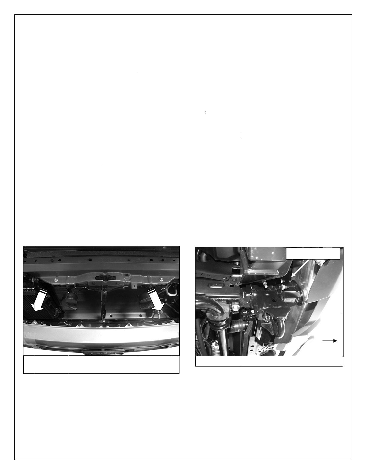
07-13 models: Open the hood. Top Brackets can either be installed from above or below front
bumper depending on model, accessories and year, (Figure 1A & 1B).
2014 models: Top Brackets must be installed from below front bumper, (Figure 1B).
3. Locate the passenger side bumper bracket bolted to the end of the frame through the gap between the
front bumper and the radiator or from below the bumper above the tow hook, (Figure 1B). If installing
from below, remove the hardware attaching the bumper cover to the cross member to access the end
of the frame and bracket, (Figure 2).
4. Select the passenger side Top Frame Bracket, (Figure 3A). Remove the top (2) factory hex nuts on the
outside and the single hex nut on the inside attaching the factory bumper bracket to the end of the
frame on the passenger side, (Figure 3B).
5. Slide the U-shaped Bracket over the top of the bumper bracket, down and over the (3) threaded studs,
(Figure 4). If installing from below, carefully pull the bottom of the bumper cover outward and slide the
Bracket up and in position. Use the factory hex nuts to attach the Top Bracket to the bumper bracket.
Snug but do not fully tighten the (3) hex nuts at this time.
6. Repeat Steps 3—5 to install the driver side Top Frame Bracket.
7. From under the front of the vehicle, remove the (2) factory tow hooks and set aside, (Figures 5 & 6).
Select the passenger side Frame Mounting Bracket, (Figure 7A).
Vehicles with small tow hook: Line up the holes in the tow hook with the slots in the Bracket. Bolt
the tow hook and Bracket to the bottom of the frame using the factory tow hook bolts, (Figure 7B).
Vehicles with large tow hooks: Bolt the driver/left side Frame Mounting Bracket directly to the
bottom of the frame with the two factory hex bolts. NOTE: Large tow hook cannot be reinstalled,
(Figure 6).
8. Repeat Step 7 to install the driver/left side Frame Mounting Bracket. Leave hardware loose at this time.
9. Select the passenger side Top Bracket, (Figure 8A). Apply the included Adhesive Backed Foam Tape
to the Bracket as needed to protect the grille opening from contact with the Bracket.
10. Slide the Top Bracket in through the opening in the bumper, (Figure 8B). Line up the (2) holes in the
Bracket with the previously installed Frame Bracket, (Figure 9A). Bolt the Top Bracket to the top of the
Frame Bracket with (2) 8mm Hex Bolts, (2) 8mm Lock Washers and (2) 8mm Flat Washers, (Figure
9B). Leave hardware loose at this time.
11. Repeat Steps 9 & 10 to install the driver side Top Bracket.
12. With assistance, place the Grille Guard face down on a clean surface in front of the vehicle. Position
the mounting tabs on the Grille Guard up to the outside of the passenger side Frame Mounting Bracket.
Line up the lower hole in the Bracket with the lower hole in the Grille Guard.
13. Insert (1) 12mm Plastic Washer between the Mounting Bracket and the Grille Guard. Line up the Grille
Guard, Washer and Bracket and bolt together with the included (1) 12mm x 35mm Hex Bolt, (1) 12mm
Lock Washer and (1) 12mm Flat Washer, (Figure 10).
14. Repeat Step 13 to attach the driver side mounting tab to the Bracket. Leave hardware loose.
15. Use the (2) previously installed 12mm Hex Bolts as a hinge. With assistance, carefully rotate the Grille
Guard up to the vehicle, (Figure 10). Line up the two remaining holes in the Mounting Brackets with the
holes in the Grille Guard. Repeat Steps 13 & 14 to attach the Grille Guard to the Brackets, (Figure 11).
Snug but do not tighten hardware at this time.
Page 1 of 8 2/17/14 (DP)
Page 3
1111222
s
g
6. Next, m
o
c
e
t
o
,
t
S
/
c
e
s
1
e
h
d
o
e
n
f
1
a
e
w
u
F
y
t
p
t
d
—
o
e
r
o
w
m
u
d
u
o
d
t
d
d
v
e
n
M
n
r
e
k
a
p
s
h
b
e
k
a
k
P
P
m
s
p
e
4
a
s
o
i
t
a
o
a
e
r
h
t
o
(
o
s
e
s
y
r
t
a
r
G
&
m
y
g
c
e
M
g
n
k
n
h
w
e
a
s
p
e
a
h
n
e
l
r
o
k
F
u
d
a
f
s
r
e
k
r
n
o
o
e
u
t
o
o
f
e
F
P
m
)
7. Repeat
8. Release
9. Adjust th
0. Slowly cl
1. Push th
2. Do perio
To p
rotect your i
over
the finish. D
For
tainless st
used
also to clea
For
loss black
(Fig 1A) 07-
Top Bra
Quick R
through
Bracket
Bracket)
Snug bu
the vehi
12mm H
level the
Nuts. Se
Model in
Guard in
(Figure
occur.
Reattac
ve to the p
ket with th
lease Bolt
he Grille G
ver the Qui
(1) 10mm
do not full
tep 16 to a
loosen the l
le to the "o
x Bolts on
Grille Guar
e Quick Rel
e Steps 23
tallation ca
ose the ho
to the "clos
5). WARNI
Grille Gua
the bottom
ic inspecti
nvestment,
not use any
el: Aluminu
the Grille G
inishes: Mil
3 Tundra b
pictured fr
ssenger si
shorter slo
ith (1) 10m
ard. Threa
ck Release.
lat Washer
tighten har
tach the dri
evers on th
en" positio
he Frame
and tighte
ease Bolt cl
27 for mo
n skip to St
d and chec
d" position.
NG! Do not
d back tow
of the bum
ns to the in
ax this prod
type of polis
polish may
ard.
soap may b
mper brac
m above
e Top Brac
in the back
m Special
(1) 10mm
Thread (1)
and (1) 10
ware at thi
er side To
Quick Rel
, (Figure 1
ounting Br
all hardwa
amping pre
e informati
p 21.
for clearan
If needed, l
completely
rds the veh
er cover wi
tallation to
uct after inst
or wax that
e used to p
used to cle
et location
et installed
of the Grill
ivot Washe
lastic Was
10mm Plas
m Nylon L
time.
Bracket to
ase Bolts,
). NOTE: It
ckets to m
re including
sure by loo
n. NOTE: T
ce. Releas
oosen the u
loosen bolt
cle and full
h the facto
make sure
lling. Regul
may contain
lish small sc
n the Grille
(Fi
in Steps 9
Guard upri
and (1) 10
er part wa
ic Washer,
ck Nut, (Fi
the Grille G
Figure 13),
may be ne
ve the Grill
the Frame
sening or ti
ilt feature o
both Quic
pper bolt o
or damage
tighten all
y hardware,
hat all hard
r waxing is r
abrasives th
atches and
uard.
g 1B) 2014
10. Line u
ght, (Figur
m Flat W
onto the th
(to protect t
ure 12), o
uard.
and pull th
essary to s
Guard, (Fi
ounting B
htening the
ly required
Release b
each Fram
to the truc
ardware, (
(Figure 2).
are is sec
commende
t could dam
cuffs on the
assenger si
p the long
12). Insert
sher, (Figu
reads. Slid
e finish on
to the Quic
Grille Gua
ightly loose
gure 15). C
ackets.
10mm Nyl
on 07-13 m
lts. Push th
e Mounting
or Grille G
igure 16 &
re and tigh
to add a pr
ge the finish
inish. Mild s
Bump
de pictured
lot in the
(1) 10mm
e 12),
the Top
the Top
Release.
d away fro
the top (2
enter and
n Lock
dels. 2014
Grille
Bracket,
ard may
17).
.
tective layer
.
ap may be
r bracket
ront
rom below
P
ge 2 of 8
2/17/14 (D
)
Page 4

i
F
t
m
o
s
b
u
T
k
k
F
d
a
S
w
RscRn
l
h
w
d
t
s
f
e
F
u
gfr
s
e
n
e
e
s
b
p
c
P
ig 2
Re
on
Fig 3B) Pas
ins
F
g 5
ove (2) top
utside of b
alled over
factory hex
mper brac
enger side
umper brac
Passen
nuts
et
op Bracket
et. Picture
ger/right
Front
Front
pictured
from belo
ront
ide Instal
emove har
ecuring bo
over to cro
emove (1)
ut on insid
Threaded
factory to
ation Pict
ware
tom of bum
s member
Fi
actory hex
of bracket
ront
(Fig 4) Reu
Bracket to
oles for
hook
red
per
3A) Passe
ame bracke
Pas
top
e factory h
nd of fram
ger side to
t illustrated
enger side
racket
x nuts to se
. Remove to
Front
cure Top
w hooks
P
ge 3 of 8
2/17/14 (D
)
Page 5

nFig
b
e
n
t
y
s
f
c
a
S
(
r
l
r
u
e
o
s
s
a
r
u
i
d
i
k
P
Fro
(Fig 6) Th
hooks ca
Front
(Fig 7B) Ins
tow hook
t
8B
heavy dut
not be rein
tall Frame B
olts. Small
Passen
factory tow
talled.
racket with
ow hook pi
ger/right
actory
tured
ide Instal
I
nsert Top B
Grille guard
eference on
ation Pict
(F
ig 7A) Pass
Front
(Fig 8A) P
acket into
pictured in
ly do not in
red
Front
nger side F
ssenger si
pening in b
talled for
tall at this t
ame Mount
e Top Brac
mper
me)
ng Bracket
et
P
ge 4 of 8
2/17/14 (D
)
Page 6

e
P
p
W
d
h
c
e
G
w
c
e
x
L
F
e
t
a
S
A
F
r
s
n
l
(Fig
B
k
5
k
u
2
2
2
2
w
v
l
m
W
a
c
G
r
r
P
Front
(Fig 9A)
Fig 10
and To
Ins
Gril
Bra
assenger s
Frame Bra
Insert
Wash
Grille
rt a Plastic
le Guard an
ket on eac
Passen
ide Top Bra
ket illustrat
(2) 8mm
(2) 8mm
(2) 8mm
(1) 12mm H
rs per side
uard up an
asher bet
the Frame
12mm Hex
ger/right
ket
d
25mm Hex
ock Washe
lat Washer
x Bolt and
hen rotate
d in positio
Front
een the
Mounting
Bolt
ide Instal
ttach Top
rame Brac
(
2) 8mm x 2
(
2) 8mm Loc
2) 8mm Flat
(
Bolts
s
ation Pict
racket to
et with:
mm Hex Bo
Washers
Washers
Fig 9B) Dri
11
(2) 1
(2) 1
(2) 1
(2) 1
(bet
red
ts
Front
er side 07-1
mm x 35m
mm Lock
mm Flat W
mm Plasti
een Grille
3 pictured f
Front
Hex Bolts
ashers
shers
Washers
uard and B
om above
acket)
P
ge 5 of 8
2/17/14 (D
)
Page 7

u"op
i
gGrup
a
a
2
W
t
h
B
s
a
S
010
l
e
s
5
n
Gth(2
Q(F
a
L
n
u
o
e
m
a
h
a
h
Q
e
n
p
e
s
a
R
P
ille Guard
right
Fi
P
ll Grille Gua
en" positio
F
g 14
12
1
0mm Quick
1
0mm Speci
0mm Flat W
1
rd to the
n
Passen
(
) 10mm Pla
ashers
Top
Release Bol
l Pivot Was
sher
ger/right
tic
racket
er
Front
ide Instal
1
mm Flat W
mm Nylon
Fro
Loos
nece
Fig 1
ation Pict
sher
ock Nut
I
sert a 10m
rille Guard
e Flat Was
) Plastic W
uick Releas
t
ig 13) Pull
n the top b
sary) to op
5
red
Plastic Wa
nd the Top
er on each
shers are r
e installatio
andle to "o
lts (only if
n the hood
sher betwe
Bracket and
uick Relea
quired for e
en" Quick
Front
n the
under
e Bolt.
ch
elease
P
ge 6 of 8
2/17/14 (D
)
Page 8

22222
2
h
hFig
e
u
,
y
h
T
a
c
e
1
e
d
r
p
g
)
e
e
o
m
o
s
w
s
o
n
a
G
d
y
e
c
s
e
e
y
s
a
S
o
e
"
o
o
o
a
t
h
g
h
L
e
p
l
d
c
t
2
o
d
u
a
u
e
g
t
7
t
u
-
e
e
r
G
y
n
s
0
w
s
u
n
r
o
l
R
u
L
u
l
e
u
m
)
e
f
t
R
P
,
Pus
to t
Grille Gua
e "closed"
16
3. Lift the l
Guard o
does not
Bracket
4. Carefull
5. Pull the
6. IMPOR
position
the vehi
7. Once th
tighten a
(Figure
and clos
Release
8. Do perio
d back
osition
Openin
vers on the
t and away
pivot to "op
(Figure 15
pull on the
ood releas
ANT! Befor
nd away fr
le and slow
hood is co
ll hardware
7). No tool
by hand
bolt to adju
ic inspecti
Passen
and closi
Quick Rele
from the ve
en" position
. WARNIN
Grille Guar
and slowl
closing th
m the vehi
ly close the
pletely clo
n the Grill
are requir
hen properl
t the clamp
ns to the in
ger/right
g the ho
se bolt to r
hicle to the
, slightly l
! Do not c
until it is fu
open the h
hood, alw
le. Pull on
hood, (Figu
ed, push t
Guard, (Fi
d to close t
adjusted.
ing pressur
tallation to
ide Instal
Fig 1
d-require
lease the
open" posi
osen the 1
mpletely lo
lly extende
od.
ys make su
he Grille G
re 14).
e Grille Gu
ure 16). P
e Quick R
oosen or ti
.
make sure
ation Pict
for 2007
lamping pr
ion, (Figur
mm uppe
sen bolts o
away from
re that the
ard to verif
rd back to i
sh down o
lease lever
hten the 1
hat all hard
red
13 model
ssure, (Fig
14). NOTE
hex bolt o
damage t
the vehicle,
rille Guard
that it is fu
ts "closed,"
the Quick
. It will req
mm Nylon
are is sec
Quick
"closed
only
re 13). Pul
: If the Grill
each Mo
the truck
(Figure 14
is in the full
ly extended
upright posi
elease lev
ire some ef
ock Nut on
re and tigh
elease in
" position
Front
l the Grille
Guard
nting
ay occur.
.
open
away from
tion and
r to tighten
ort to open
the Quick
.
Com
lete Installa
P
ge 7 of 8
ion
2/17/14 (D
)
 Loading...