

Page 1

INSTALLATION INSTRUCTIONS
3" SIDEBAR
-
Page 2
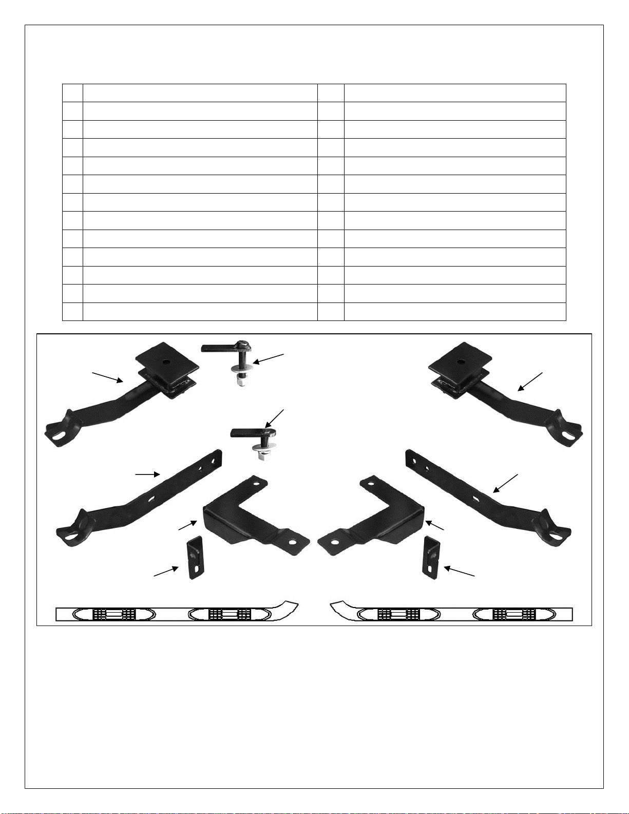
07-14 JEEP PATRIOT
PARTS LIST:
1 Driver/Left Sidebar 10 12mm Lock Washers
1 Passenger/Right Sidebar 14 12mm x 37mm OD x 3mm Flat Washers
1 Driver/Left Front Mounting Bracket 10 12-1.75mm Hex Nuts
1 Passenger/Right Front Mounting Bracket 2 10-1.5mm x 35mm Hex Bolts
1 Driver/Left Front Frame Bracket 2 10mm Lock Washers
1 Passenger/Right Frame Bracket 4 10mm x 30mm OD x 2.5mm Flat Washer
1 Driver/Left Front Support Bracket 2 10mm Hex Nuts
1 Passenger/Right Front Support Bracket 2 8-1.25mm x 35mm Hex Bolts
1 Driver/Left Rear Mounting Bracket 8 8-1.25mm x 25mm Hex Bolts
1 Passenger/Right Rear Mounting Bracket 10 8mm Lock Washers
4 12-1.75mm x 35mm Bolt Plates 12 8mm x 24mm OD x 2mm Flat Washers
2 12-1.75mm x 60mm Long Bolt Plates 2 8mm Hex Nuts
4 12-1.75mm x 35mm Hex Bolts
Passenger/Right
Rear Mounting
Bracket
(2) 12mm x 60mm
Long Bolt Plates
(4) 12mm x 35mm
Bolt Plates
Driver/Left Rear
Mounting Bracket
Passenger/Right Front
Mounting Bracket
Driver/Left Front
Mounting Bracket
Passenger/Right Front
Support Bracket
Passenger/Right
Frame Mounting
Bracket
Passenger/Right Sidebar Driver/Left Sidebar
Front
Driver/Left Frame
Mounting Bracket
Driver/Left Front
Support Bracket
PROCEDURE:
REMOVE CONTENTS FROM BOX. VERIFY ALL PARTS ARE PRESENT. READ
INSTRUCTIONS CAREFULLY BEFORE STARTING INSTALLATION. DRILLING AND
CUTTING IS REQUIRED. ASSISTANCE IS RECOMMENDED.
1. Starting at the driver side front of the vehicle, locate the three factory holes, (1 round and 2
oval holes), in the bottom of the left front floor panel, (Figure 1). Insert (1) 12mm x 35mm Bolt
Plate into the smaller, (inner), oval hole and feed the threaded end back out through the larger,
(outer), oval hole, (Figures 2A & 2B). Next, insert (1) 12mm Bolt Plate into the oval hole in the
bottom of the inner frame channel, (Figure 3).
3" SIDEBAR
Page 1 of 5 8/15/13 REV1 (DP)
Page 3

3" SIDEBAR
07-14 JEEP PATRIOT
2. Attach the driver side front Frame Mounting Bracket to the (2) Bolt Plates with the included (2)
12mm Flat Washers, (2) 12mm Lock Washers and (2) 12mm Hex Nuts, (Figure 4). Do not
tighten hardware at this time.
3. Select the driver/left front Sidebar Mounting Bracket. Bolt the Mounting Bracket to the back of
the Frame Bracket with the included (2) 12mm Hex Bolts, (4) 12mm Flat Washers, (2) 12mm
Lock Washers and (2) 12mm Hex Nuts, (Figure 5B). Do not tighten at this time.
4. Next, select the driver side Front Support Bracket, (Figure 5A). Attach the Support Bracket to
the front side of the Mounting Bracket with (1) 10mm Hex Bolt, (2) 10mm Flat Washers, (1)
10mm Lock Washer and (1) 10mm Hex Nut, (Figure 5B). Leave completely loose at this time.
5. Move along the side of the vehicle toward the rear. Locate the large oval slot in the floor panel.
Insert (1) 12mm x 60mm Long Bolt Plate into the slot, (Figure 6A). NOTE: Rotate the Bolt
Plate so that the plate is across, not inline with the oval hole, (Figure 6B).
6. Attach the driver side rear Mounting Bracket to the Long Bolt Plate with (1) 12mm Flat Washer,
(1) 12mm Lock Washer and (1) 12mm Hex Nut (Figure 7).
7. With the Sidebar Bracket hardware loose, pull the Brackets outward away from the vehicle for
proper clearance.
8. Select the driver/left Sidebar and carefully place it onto the (2) Mounting Brackets. Attach the
Sidebar to the Brackets with the included (4) 8mm x 25mm Hex Bolts, (4) 8mm Lock Washers,
and (4) 8mm Flat Washers (Figures 7 - 9). Leave loose at this time.
9. Line up the Front Support Bracket with the back of the pinch weld, (Figure 8). Push the
Support Bracket up as high as possible to where the pinch weld meets the floor panel. Snug
but do not fully tighten hardware.
10. Check the Sidebar for level. Once properly aligned and adjusted, tighten all hardware.
IMPORTANT: If the Support Bracket is too low and close to the edge of the pinch weld, loosen
the Support Bracket and front Bracket hardware. Push the Bracket and Support Bracket up a
little into position against the floor panel and away from the edge of the pinch weld, (Figure 8).
Level and adjust the Sidebar properly and tighten all hardware.
11. Use the hole in the Support Bracket as a guide to mark the drilling location on the back of the
pinch weld, (Figure 8). Once you have marked the location, temporarily remove the Sidebar,
the front Mounting Bracket and Support Bracket. Remove the plastic clips securing the plastic
rocker cover to the rocker panel.
12. Use a 5/16” drill bit and carefully drill the marked location. NOTE: The plastic rocker panel
cover may need to be trimmed to clear the hex bolt for the Support Bracket. IMPORTANT: Any
cutting or drilling tool may break or shatter. Government regulations require safety glasses &
equipment at all times when cutting or drilling.
13. Re-install the driver side front Mounting Bracket and Support Bracket. Attach the Support
Bracket to the pinch weld with (1) 8mm x 35mm Hex Bolt, (1) 8mm Lock Washer, (2) 8mm Flat
Washers and (1) 8mm Hex Nut, (Figure 9). NOTE: Insert the 8mm Hex Bolt with (1) 8mm Flat
Washer through the pinch weld first, then through the Bracket. Cut the rocker panel cover as
required and reinstall the cover with the factory plastic clips. Reinstall the Sidebar.
14. Align and adjust the Sidebar and Brackets and tighten all hardware.
15. Repeat Steps 2 – 14 for passenger Sidebar installation.
16. Do periodic inspections to the installation to make sure that all hardware is secure and tight.
To protect your investment, wax this product after installing. Regular waxing is recommended to add a protective layer
over the finish. Do not use any type of polish or wax that may contain abrasives that could damage the finish.
For stainless steel: Aluminum polish may be used to polish small scratches and scuffs on the finish. Mild soap may be
used also to clean the Sidebar.
For gloss black finishes: Mild soap may be used to clean the Sidebar
Page 2 of 5 8/15/13 REV1 (DP)
Page 4

Driver Side Installation Pictured
Front
(Fig 1) Driver side front mounting location
Front
Fig 2B
Insert (1) 12mm Bolt Plate into the inner small
oval hole and back out the larger oval hole
3" SIDEBAR
07-14 JEEP PATRIOT
12mm Bolt Plate
12mm Flat Washer
12mm Lock Washer
12mm Hex Nut
Fig 2A
Driver side inner frame channel
Front
(Fig 3) Insert (1) 12mm Bolt Plate into the hole in
the bottom of the inner frame channel
Page 3 of 5 8/15/13 REV1 (DP)
Page 5

Fig 4
Front
Fig 5B
Fig 6B
Front
Driver Side Installation Pictured
12mm Flat Washer
12mm Lock Washer
12mm Hex Nut
10mm Hex Bolt
(2) 10mm Flat Washers
10mm Lock Washer
10mm Hex Nut
(2) 12mm Hex Bolts
(2) 12mm Lock Washers
(4) 12mm Flat Washers
(2) 12mm Hex Nuts
Rear
3" SIDEBAR
07-14 JEEP PATRIOT
Front
(Fig 5A) Driver side front
Support Bracket pictured
(Fig 6A) 12mm Long Bolt Plate
Page 4 of 5 8/15/13 REV1 (DP)
Page 6

p
Fig 7
12mm Flat Washer
12mm Lock Washer
12mm Hex Nut
8mm x 35mm Hex Bolt
8mm Lock Washer
(2) 8mm Flat Washers
8mm Hex Nut
Driver Side Installation Pictured
(2) 8mm x 25mm Hex Bolts
(2) 8mm Lock Washers
(2) 8mm Flat Washers
Drill 5/16" hole through marked
spot on pinch weld. Do not drill
close to the edge of the pinch weld
Rear
10mm Hex Bolt
(2) 10mm Flat Washers
10mm Lock Washer
10mm Hex Nut
Front
Fig 8
3" SIDEBAR
07-14 JEEP PATRIOT
Front
Adjust Sidebar. Loosen 10mm Bolt
and push Support Bracket up
against the floor to move slot
away from edge of pinch weld
Fig 9
(2) 8mm x 25mm Hex Bolts
(2) 8mm Lock Washers
(2) 8mm Flat Washers
Installation Com
Page 5 of 5 8/15/13 REV1 (DP)
lete
 Loading...