

ARIES 0503 User Manual
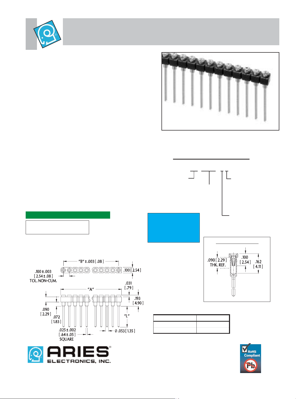
Series 0503 Pin-Line Collet Sockets
with Wire Wrap Pins
Note: Aries specializes in custom design and production. In addition to the
standard products shown on this page, special materials, platings, sizes, and
configurations can be furnished, depending on quantities. Aries reserves the
right to change product specifications without notice.
ALL DIMENSIONS
: INCHES [MILLIMETERS]
CONTACT DETAIL
XX-0503-XX
ORDERING INFORMATION
FEATURES:
• Rows of socket strips may be mounted on any centers and
are end-to-end or side-by-side stackable for .100 [2.54] grid
or matrix patterns.
• Available with wire wrap or solder tail pins. Consult Data
Sheet No. 12013 for solder tail pins.
• ”Break” feature allows strips to be cut to the number of
positions desired.
SPECIFICATIONS:
• Body material is Black UL 94-V0 Glass-filled 4/6 Nylon.
• Pin body is Brass Alloy 360 1/2 hard per UNS C36000
ASTM-B16-00.
• Pin body plating is either 10μ [.25μm] min. Gold per MIL-G45204 or 200μ [5.08μm] min. 93/7 Tin/Lead per ASTM
B545 or 200μ [5.08μm] min. Tin per ASTM B545 Type 1
over 100μ [2.54μm] min. Nickel per SAE-AMS-QQ-N-290.
• 4-fingered collet contact is Beryllium Copper Alloy per
UNS C17200 ASTM-B194-01.
• Contact plating is 30μ [.76μm] min. Gold per MIL-G-45204
over 50μ min. [1.27μm] Nickel per SAE-AMS-QQ-N-290.
• Contact current rating=3 Amps.
• Operating Temp.= -67°F to 221°F [-55°C to 105°C] Tin
= -67°F to 257°F [-55°C to 125°C] Gold
• Insertion Force=180 grams/pin; Withdrawal Force=90
grams/pin; Normal Force=140 grams/pin; based on a .018
[.46] dia. test lead.
• Accepts leads .015-.025 [.38-.64] in dia., .110-.162
[2.79-4.11] long.
MOUNTING CONSIDERATIONS:
•Suggested PCB hole size=.045 ± .002 [1.14 ± .05] dia.
No. of pins:
1 to 25
Series
2=2 level wire wrap
3=3 level wire wrap
Plating:
0=Gold collet/Tin
shell
0TL=Gold collet/
Tin/Lead shell
1=Gold collet/Gold
shell
Pin-Line collet sockets
also available with
solder tail pins.
Consult Data Sheet
No. 12013.
Dim. “L ”
2 level wir e wr ap
. 360 [9. 14]
3 level wir e wr ap
. 500 [12. 70]
All tolerances ± .005 [.13]
unless otherwise specified
“A”=NO. OF PINS PER ROW X .100 [2.54]
“B”=(NO. OF PINS PER ROW - 1) X .100 [2.54]
12014
REV.D
PRINTOUTS OF THIS DOCUMENT MAY BE OUT OF DATE AND SHOULD BE CONSIDERED UNCONTROLLED
Frenchtown, NJ USA
TEL: (908) 996-6841
FAX: (908) 996-3891
http://www.arieselec.com • info@arieselec.com
abc
 Loading...