

Page 1

Zoom ®
Owner/Operator Manual
Manuel Du Proprietaire/Utilisateur
Models
915157 - Zoom 34
915159 - Zoom 42
915161 - Zoom 50
915169 - Zoom 34 CARB
915171 - Zoom 42 CARB
Gasoline containing up to 10% ethanol (El0) or up to 10% MTBE (methyl tertiary butyl ether)is
acceptable for use in this machine.
The use of any gasoline exceeding 10% ethanol (El0) or 10% MTBE will void the product warranty.
II est possible d'utiliser de I'essence contenant jusqu'a 10% d'ethanol (El0) ou 10% de MTBE
(ether methyl-tertiobutylique) sur cette machine.
L'utilisation d'une essence contenant plus de 10% d'ethanol (El0) ou de 10% de MTBE annulent la
garantie.
ENGLISH
,_ _ (_ FRAN(_AIS 03997700B1/11
Printed in USA
Page 2
/ Y.*_:] i _ [o]_ _[o] _/ / _ _/ _
SAFETY .......................... 4
ASSEMBLY ....................... 9
CONTROLS AND FEATURES ....... 11
OPERATION ..................... 12
MAINTENANCE SCHEDULE ........ 16
SERVICE AND ADJUSTMENTS ..... 17
STORAGE ....................... 24
TROUBLESHOOTING ............. 25
SERVICE PARTS ................. 26
ACCESSORIES ................... 26
SPECIFICATIONS ................. 27
WARRANTY ..................... 29
II_liill={o]_lr_]ilKo] _I
NON-ENGLISH MANUALS
Manuals in languages other than
English may be obtained from your
Dealer. Visit your dealer or
www.ariens.com for a list of
languages available for your
equipment.
Manuals printed in languages other
than English are also available as a
free download on our website:
http://www.ariens.com
MANUALES EN IDIOMAS
DIFERENTES DEL INGLES
Puede obtener manuales en
idiomas diferentes del ingles en su
distribuidor. Visite a su distribuidor
o vaya a www.ariens.com para
obtener una lista de idiomas
-_ disponibles para su equipo.
Tambien puede imprimir manuales
en idiomas diferentes del ingles
descargandolos gratuitamente de
nuestra pagina Web:
http://www.ariens.com
MANUELS NON ANGLAIS
Des manuels dans differentes
langues sont disponibles chez
votre revendeur. Rendez-vous
chez votre revendeur ou allez sur
-_ le site www.ariens.com pour
consulter la liste des langues
disponibles pour votre equipement.
Les manuels imprimes dans des
langues differentes de I'anglais
sont egalement disponibles en
telechargement gratuit sur notre
site Web:
http://www.ariens.com
THE MANUAL
Before operation of unit, carefully and
completely read your manuals. The contents
will provide you with an understanding of
safety instructions and controls during normal
operation and maintenance.
All reference to left, right, front, or rear are
given from operator seated in operation
position and facing the direction of forward
travel.
ENGINE MANUAL
The engine on this unit is covered by a
separate manual specific to the engine. This
manual is included in the literature package
that shipped with the unit. Refer to this
manual for engine service recommendations.
If the engine manual is not available, contact
the engine manufacturer for a replacement
manual.
MODEL AND SERIAL NUMBERS
When ordering replacement parts or making
service inquiries, know the Model and Serial
numbers of your unit and engine.
Numbers are located on the product
registration form in the unit literature
package. They are printed on a serial number
label, located on the frame of your unit under
the seat (figure 1).
GB-2
Page 3

UnitSerialNumberLabel
NOTE:AcompletePartsmanualmaybe
downloadfromwww.ariens.comonthe
internet.
DELIVERY
Customer Note: If you have purchased this
product without complete assembly and
instruction by your retailer, it is your
responsibility to:
Read and understand all assembly
instructions in this manual. If you do
not understand or have difficulty
following the instructions, contact your
nearest Ariens Dealer for assistance.
NOTE: To locate your nearest Ariens Dealer,
go to www.ariens.com on the internet.
Figure 1
Record Unit Model and Serial
numbers here.
Record Engine Model and Serial
numbers here.
PRODUCT REGISTRATION
The Ariens dealer must register the product
at the time of purchase. Registering the
product will help the company process
warranty claims or contact you with the latest
service information. All claims meeting
requirements during the limited warranty
period will be honored, whether or not the
product registration card is returned. Keep a
proof of purchase if you do not register your
unit.
Customer Note: If the Dealer does not
register your product, please fill out, sign and
return the product registration card to Ariens
or go to www.ariens.com on the internet.
,_ WARNING: Improper assembly
or adjustments can cause serious
injury.
Before Attempting to Operate Your
Unit:
1. Make sure all assembly has been
properly completed.
2. Understand all Safety Precautions
provided in the manuals.
3. Review control functions and operation
of the unit. Do not operate the unit
unless all controls function as described
in this manual.
4. Review recommended lubrication,
maintenance and adjustments.
5. Review Limited Warranty Policy.
6. Fill out a product registration card and
return the card to the Ariens Company or
go to www.ariens.com.
DISCLAIMER
Ariens reserves the right to discontinue,
change, and improve its products at any time
without notice or obligation to the purchaser.
The descriptions and specifications contained
in this manual were in effect at printing.
Equipment described within this manual may
be optional. Some illustrations may not be
applicable to your unit.
UNAUTHORIZED REPLACEMENT
PARTS
Use only Ariens replacement parts. The
replacement of any part on this unit with
anything other than an Ariens authorized
replacement part may adversely affect the
performance, durability, and safety of this unit
and may void the warranty. Ariens disclaims
liability for any claims or damages, whether
warranty, property damage, personal injury or
death arising out of the use of unauthorized
replacement parts.
GB-3
Page 4

[,:'Y-'1al=1i'I
WARNING: This cutting machine
is capable of amputating hands
and feet and throwing objects.
Failure to observe the safety
instructions in the manuals and on
decals could result in serious
injury or death.
Slopes are a major factor related
to loss-of-control and tip-over
accidents. Operation on all slopes
requires extra caution.
Tragic accidents can occur if the
operator is not alert to the
presence of children. Never
assume that children will remain
where you last saw them.
Gasoline is extremely flammable
and the vapors are explosive,
handle with care.
Disengage attachment, stop unit
and engine, remove key, engage
parking brake, and allow moving
parts to stop before leaving
operator's position.
SAFETY ALERTS
Look for these symbols to point
out important safety
precautions. They mean:
Attention!
Personal Safety Is
Involved!
Become Alert!
Obey The Message!
The safety alert symbol is used in decals and
with this manual. Understand the safety
message. It contains important information
about personal safety.
,_ WARNING: POTENTIALLY
HAZARDOUS SITUATION! If not
avoided, COULD RESULT in
death or serious injury.
_ DANGER: IMMINENTLY
HAZARDOUS SITUATION! If not
avoided, WILL RESULT in death
or serious injury.
A AUTION: POTENTIALLY
HAZARDOUS SITUATION! If not
avoided, MAY RESULT in minor
or moderate injury. It may also be
used to alert against unsafe
practices.
NOTATIONS
NOTE: General reference information for
proper operation and maintenance practices.
IMPORTANT: Specific procedures or
information required to prevent damage to
unit or attachment.
SAFETY DECALS AND
LOCATIONS
ALWAYS replace missing or damaged Safety
Decals. Refer to figure 2 for Safety Decal
locations.
GB-4
Page 5

5
1.DANGER!
Figure2
&DANGER!
Avoid injury - Stay clear of
rotating parts.
OL1816
2.CAUTION
No smoking.
IMPORTANT: DO NOT overfill.
(_ illfuel tank to below bottom of
filler neck (see FILLING FUEL
TANK on page 13).
,_ WARNING: Over Filling may cause
severe damage to evaporative
system !
Never fill fuel tank when engine is
running, hot or unit is indoors. Never
overfill fuel tank.
Replace fuel cap securely and clean
up spilled fuel.
3L q.
OL1809
Always keep feet and hands
away from rotating parts.
Always stand clear of discharge
area. Do not direct discharge
toward other people.
D_-_L_ Keep people away from unit
while operating.
OL1812
Shut off engine, remove key,
and read manual before you
adjust or repair unit.
NO STEP! Always keep feet
away from rotating parts.
OL1813
GB-5
Page 6
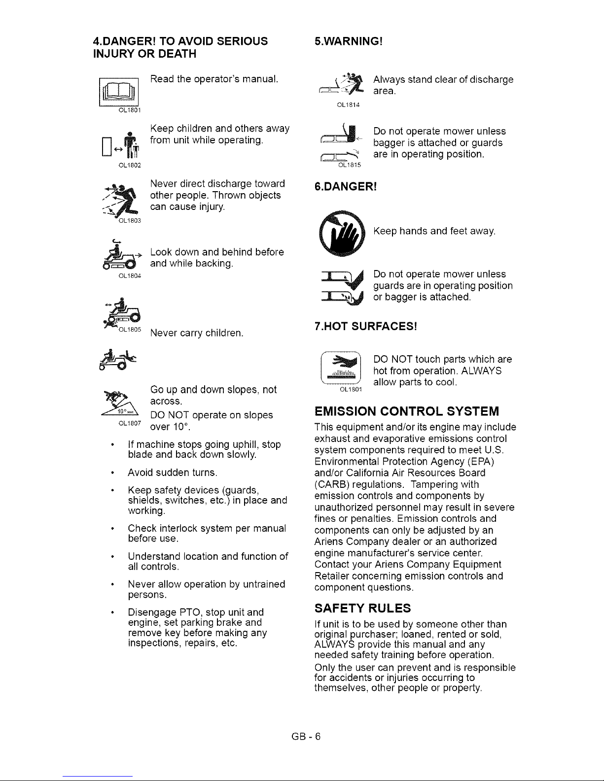
4.DANGER! TO AVOID SERIOUS
INJURY OR DEATH
Read the operator's manual.
OL1801
Keep children and others away
D [ from unit while operating.
OL1802
Never direct discharge toward
_-_=_, other people. Thrown objects
_-_>__ can cause injury.
OL1803
_.> Look down and behind before
and while backing.
OL1804
Never carry children.
Go up and down slopes, not
across.
DO NOT operate on slopes
OL1807over 10°.
If machine stops going uphill, stop
blade and back down slowly.
Avoid sudden turns.
Keep safety devices (guards,
shields, switches, etc.) in place and
working.
Check interlock system per manual
before use.
Understand location and function of
all controls.
Never allow operation by untrained
persons.
Disengage PTO, stop unit and
engine, set parking brake and
remove key before making any
inspections, repairs, etc.
&WARNING!
OL1814
OL1815
Always stand clear of discharge
area.
Do not operate mower unless
bagger is attached or guards
are in operating position.
&DANGER!
Keep hands and feet away.
_r------_--_ Do not operate mower unless
guards are in operating position
--[-_,_]_ or bagger is attached.
7.HOT SURFACES!
OL1801
DO NOT touch parts which are
hot from operation. ALWAYS
allow parts to cool.
EMISSION CONTROL SYSTEM
This equipment and/or its engine may include
exhaust and evaporative emissions control
system components required to meet U.S.
Environmental Protection Agency (EPA)
and!or California Air Resources Board
(CARB) regulations. Tampering with
emission controls and components by
unauthorized personnel may result in severe
fines or penalties. Emission controls and
components can only be adjusted by an
Ariens Company dealer or an authorized
engine manufacturer's service center.
Contact your Ariens Company Equipment
Retailer concerning emission controls and
component questions.
SAFETY RULES
If unit is to be used by someone other than
original purchaser; loaned, rented or sold,
ALWAYS provide this manual and any
needed safety training before operation.
Only the user can prevent and is responsible
for accidents or injuries occurring to
themselves, other people or property.
GB-6
Page 7

Read,understand,andfollowallsafety
practicesinOwner/OperatorManualbefore
assembling,usingorworkingonthismower.
ALWAYSremovekeyfromignitionandwire
fromsparkplugbeforeassembly,orworking
onthisunit.
Inspectunitbeforeeachusefor:missingor
damageddecalsandshields,correctly
operatingsafetyinterlocksystem,and
deteriorationofgrasscatchers.Replaceor
repairasneeded.
ALWAYScheckoverheadandside
clearancescarefullybeforeoperation.
ALWAYSbeawareoftrafficwhencrossingor
operatingalongstreetsorcurbs.
Keepchildren,people,andpetsaway.Be
alertandshutoffunitifanyoneenterswork
area.Keepchildrenunderwatchfulcareofa
responsibleadult.
NEVERallowchildrentooperateorplayon
ornearunit.
Keepareaofoperationclearofalltoys,and
debris.Thrownobjectscancauseinjury.
Stayalertforhiddenhazards,holes,andruts.
Avoidunevenorroughterrain.DONOT
operateneardrop-offs,ditches,or
embankments.Unitcansuddenlyturnoverif
awheelisovertheedgeofaclifforditch,orif
anedgecavesin.
Dust,fog,etc.canreducevisionandcause
anaccident.Operateunitonlywhenthereis
goodvisibilityandlight.
Dataindicatesthatoperators,age60and
above,areinvolvedinalargerpercentageof
ridingmowerrelatedinjuries.These
operatorsshouldevaluatetheirabilityto
operatetheridingmowersafelyenoughto
protectthemselvesandothersfromserious
injury.
Onlytrainedadultsmayoperateunit.Training
includesbeingfamiliarwithcontrolsand
actualoperation.
NEVERoperateunitafterorduringtheuseof
medication,drugsoralcohol.
NEVERallowanyonetooperatethisunit
whentheiralertnessorcoordinationis
impaired.
Wearadequatesafetygear,sturdyshoes,
andprotectivegloves.
DONOTwearlooseclothingorjewelryand
tiebackhairthatmaygetcaughtinrotating
parts.
Protecteyes,faceandheadfromobjectsthat
maybethrownfromunit.Wearappropriate
hearingprotection.Alwayswearsafety
gogglesorsafetyglasseswithsideshields
whenoperatingmower.
Avoidsharpedges.Sharpedgescancut.
Movingpartscancutofffingersorahand.
ALWAYSkeephandsandfeetawayfromall
rotatingpartsduringoperation.Rotatingparts
cancutoffbodyparts.
ALWAYSkeephandsawayfromallpinch
points.
Startandoperateunitonlywhenseatedin
operator'sposition.Steeringcontrollevers
mustbeinneutral,PTOdisengagedand
parkingbrakesetwhenstartingengine.
ALWAYSkeepbodyandhandsawayfrom
pinholesornozzleswhichejecthydraulic
fluidunderpressure.
DONOTtouchunitpartswhichmightbehot
fromoperation.Allowpartstocoolbefore
attemptingtomaintain,adjustorservice.
NEVERplaceyourhandsoranypartofyour
bodyorclothinginsideornearanymoving
partwhileunitisrunning.
NEVERdirectdischargetowardspersonsor
property.Thrownobjectsmayricochetback
towardsoperator.ALWAYSstandclearofthe
dischargearea.
ALWAYSdisengageattachment,stopunit
andengine,placecontrolleversinneutral,
removekey,engageparkingbrake,andallow
movingpartstostopbeforeleaving
operator'sposition.
Useextremecautionongravelsurfaces.
DisengagePTOwhenattachmentisnotin
useandwhencrossinggravelsurfaces.
DONOToperateunitifsafetyinterlock
systemisdamagedordisabled.Checksafety
interlockbeforeeachuse.
ALWAYSremovekeytopreventunauthorized
use.
DO NOT operate at too fast a rate. Slow
down before turning.
Stop engine before removing grass catcher or
unclogging chute.
DO NOT mow on wet grass. Reduced
traction could cause sliding.
DO NOT try to stabilize the machine by
putting your foot on the ground.
Know the weight of loads. Limit loads to those
you can safely control and the unit can safely
handle.
ALWAYS keep protective structures, guards
and panels in good repair, in place and
securely fastened.
Do not operate without either entire grass
catcher or the discharge guard in place.
DO NOT operate in reverse unless absolutely
necessary. ALWAYS look down and behind
before and while backing; especially for
children.
Follow the manufacturer's recommendations
for wheel weights or counterweights to
improve stability when using attachments.
NEVER carry passengers-especially
children-even with blades off.
Use extra care when approaching blind
corners or objects that may obscure vision of
hidden obstacles and children.
If you cannot back up a slope or you feel
uneasy on it, do not mow it.
Operation on slopes may lead to loss of
steering control. When operating on slopes
be prepared to react to an emergency
situation:
GB-7
Page 8

Returnsteeringleverstoneutral
position.
Immediatelysetparkingbrake.
TurnoffPTOandengine.
Mowupanddownslopes,notacrossthem.
Useslowspeedonanyslope.Tiresmaylose
tractiononslopeseventhoughthebrakesare
functioningproperly.
Keepallmovementsontheslopeslow and
gradual, DO NOT make sudden changes in
speed or direction.
Use extra care while operating machines with
grass catcher or other attachments. They can
affect stability of the machine.
Avoid starting, stopping, or turning on a
slope. If tires lose traction, disengage the
blades and proceed slowly straight down the
slope.
DO NOT operate on slopes over 10°.
DO NOT park on slopes unless necessary. If
unit is parked on a slope, ALWAYS chock or
block wheels and set parking brake.
DO NOT disengage or bypass transmission
and coast downhill.
Tow only with a machine that has a hitch
designed for towing. Do not attach towed
equipment except at the hitch point.
Follow the manufacturer's recommendations
for weight limits for towed equipment and
towing on slopes.
Maximum Tongue weight: 30 Ibs.
Maximum Trailer weight: 300 Ibs.
Do not use hitch with bagger attached.
Do not use on steep hills or slopes.
Do not park on hills when trailer is attached.
Do not use with any ground engaging
equipment.
NEVER allow children or others in or on
towed equipment.
On slopes, the weight of the towed equipment
may cause loss of traction and loss of control.
Travel slowly and allow extra distance to stop.
Use extra care when loading or unloading
unit onto trailer or truck.
Secure unit chassis to transport vehicle.
NEVER secure from rods or linkages that
could be damaged.
DO NOT transport machine while engine is
running.
ALWAYS turn off power to attachment and
properly drain fuel when transporting unit.
Keep unit free of grass clippings, leaves, and
other debris. Clean up oil or fuel spills.
This product is equipped with an internal
combustion type engine. DO NOT use unit on
or near any unimproved, forest-covered or
brush covered land unless exhaust system is
equipped with a spark arrester meeting
applicable local, state or federal laws. A spark
arrester, if it is used, must be maintained in
effective working order by operator.
Fuel is highly flammable and its vapors are
explosive. Handle with care. Use only an
approved gasoline container with an
appropriately sized dispensing spout.
NO smoking, NO sparks, NO flames.
ALWAYS allow engine to cool before
servicing.
NEVER fill fuel tank when engine is running
or hot from operation.
NEVER fill or drain fuel tank indoors.
NEVER overfill fuel tank.
Properly remove fuel before tipping unit.
Replace fuel cap securely and clean up
spilled fuel.
NEVER fill containers inside a vehicle or on a
truck or trailer bed with a plastic liner. Always
place containers on the ground away from
your vehicle before filling.
When practical, remove gas-powered
equipment from the truck or trailer and refuel
it on the ground. If this is not possible, then
refuel such equipment on a trailer with a
portable container, rather than from a
gasoline dispenser nozzle.
Keep the nozzle in contact with the rim of the
fuel tank or container opening at all times until
fueling is complete. Do not use a nozzle lock-
open device.
If fuel is spilled on clothing, change clothing
immediately.
Avoid Electric Shock. Objects contacting both
battery terminals at the same time may result
in injury and unit damage. DO NOT reverse
battery connections.
Explosive Gases from battery can cause
death or serious injury. Poisonous battery
fluid contains sulfuric acid and its contact with
skin, eyes or clothing can cause severe
chemical burns.
NO flames, NO sparks, NO smoking near
battery.
ALWAYS wear safety glasses and protective
gear near battery. Use insulated tools.
DO NOT TIP battery beyond a 45° angle in
any direction.
ALWAYS keep batteries out of reach of
children.
Battery posts, terminals and related
accessories contain lead and lead
compounds, chemicals known to the State of
California to cause cancer and reproductive
harm. Wash hands after handling.
Reverse connections may result in sparks
which can cause serious injury. Always
connect positive (+) lead of charger to
positive (+) terminal, and negative (-) lead to
negative (-) terminal.
ALWAYS disconnect negative (-) cable FIRST
and positive (+) cable SECOND. ALWAYS
connect positive (+) cable FIRST, and
negative (-) cable SECOND.
GB-8
Page 9

A frozen battery can explode and result in
death or serious injury. DO NOT charge or
jump start a battery containing frozen fluid.
Thaw the battery before putting on a charger
or jump starting.
ALWAYS keep protective structures, guards,
and panels in good repair, in place and
securely fastened. NEVER modify or remove
safety devices.
DO NOT change engine governor settings or
over-speed engine.
Fumes from engine exhaust can cause injury
or death. DO NOT run engine in an enclosed
area. Always provide good ventilation.
ALWAYS maintain unit in safe operating
condition. Damaged or worn out muffler can
cause fire or explosion.
Stop and inspect equipment if you strike an
object or if there is an unusual vibration.
Repair, if necessary, before restarting. Never
make adjustments or repairs with the engine
running.
Mower blades are sharp and can cut you.
Wrap the blade(s) or wear gloves, and use
extra caution when servicing them. NEVER
weld or straighten mower blades.
Rotation of one blade may cause rotation of
the other blades.
Check brake operation frequently. Adjust and
service as required.
Keep all hardware properly tightened.
Stored energy in springs can cause injury.
Maintain or replace safety and instruction
labels, as necessary.
Never store the machine or fuel container
inside a building where there is an open
flame, such as a water heater.
Shut off fuel (if provided) and allow engine to
cool completely before storing in closed area
or covering unit.
Clean grass and debris from unit, especially
from around muffler and engine, to help
prevent fires.
For extended storage, clean unit thoroughly.
See storage section and Engine Manual for
proper storage.
Use only attachments or accessories
designed for your unit.
Check attachment components frequently. If
worn or damaged, replace with
manufacturer's recommended parts.
V_,_,.$1=1_v_I:]t'i
WARNING: AVOID INJURY.
Read and understand the entire
Safety section before proceeding.
Tools Required
Adjustable wrench
Petroleum jelly or dielectric grease.
Unpack Unit
Remove unit and all other components from
the shipping container. Engage transmission
bypass lever (see MOVING UNIT
MANUALLYon page 15). Push unit from
container onto a level surface. Disengage
transmission bypass lever.
Connect Battery
See Battery Removal and Installation on
page 20 and perform steps 2 and 3 in the
installation section.
Place Unit in Operating Position
(Figure 3)
NOTE: The seat is shipped with the seat
positioned as far back as possible.
1. Push steering levers aside and tip seat
up.
2. Adjust the seat as needed (see SEAT
ADJUSTMENT on page 17).
3. Remove hardware from top hole of the
steering lever (Figure 3). Slide steering
lever back to align slot with hole at the
top of the steering pivot arm.
NOTE: Do not tighten hardware before
reviewing ADJUSTING STEERING LEVERS
on page 22. If no adjustment is desired
tighten hardware.
4. Adjust steering levers (see ADJUSTING
STEERING LEVERS on page 22).
1
3
2
1. Steering Lever 3. Steering Lever
2. Steering Pivot Hardware
Arm
Figure 3
Check Engine Oil Level
Refer to Engine Manual.
GB-9
Page 10
Check Tire Pressure
CAUTION: Avoid injury!
Explosive separation of tire and
rim parts is possible when they
are serviced incorrectly:
Do not attempt to mount a tire
without the proper equipment
and experience to perform the
job.
Do not inflate the tires above
the recommended pressure.
Do not weld or heat a wheel
and tire assembly. Heat can
cause an increase in air
pressure resulting in an
explosion. Welding can
structurally weaken or deform
the wheel.
Do not stand in front or over
the tire assembly when
inflating. Use a clip-on chuck
and extension hose long
enough to allow you to stand
to one side.
See SPECIFICATIONS on page 27.
Level Mower Deck
See LEVELLING AND ADJUSTING PITCH
OF MOWER DECK on page 18.
Fill Fuel Tank
Fill fuel tank. DO NOT OVERFILL! See
FILLING FUEL TANK on page 13.
Check Safety Interlock System
A ARNING: Safety interlockfailure and improper operation of
unit can result in death or serious
injury. Check system before each
use to make sure it is functioning
properly.
See Safety Interlock System on page 12.
Check function of all controls
See OPERATION on page 12.
GB - 10
Page 11

[_o]_ij_o_ r-'__Im]I_1_i uL_"]
3
\
10
915157,169
13
915159,161,171
11
1 2
Figure 4
1. ignition Switch
2. PTO Switch
3. Seat
4. Fuel Level
5. Steering Levers
6. Fuel Tank
7. Mower Lift Pedal
8. Mower Deck
9. Discharge Chute
10. Parking Brake
11. Choke (915159, 161, 171)
12. Throttle (915159, 161, 171)
13. Throttle/Choke Lever (915157, 169)
GB- 11
Page 12

[e]_:1;l.*t / [e]_
WARNING: AVOID INJURY.
Read and understand the entire
Safety section before proceeding.
CONTROLS AND FEATURES
See figure 4 for all controls and features
locations.
Safety Interlock System
WARNING: Safety interlock failure
and improper operation of unit can
result in death or serious injury.
Check system before each use to
make sure it is functioning
properly.
Test Steering Lever PTO
1 Neutral Position Off
2 Neutral Position On
3 Neutral Position Off
4*+ Out of Neutral Position Off
5*+ Neutral Position On
Test with engine running.
+ Operator lifts off seat.
Perform the following tests to ensure the
safety interlock system is working properly. If
the unit does not perform as stated contact
your Ariens dealer for repairs.
Ignition Switch
1
Operate ignition switch
with a removable key.
Ignition switch has three
positions: Stop (1),
Run (2), Start (3). See
STARTING AND
SHUTTING OFF
ENGINE on page 14 for
detailed instructions on
how to start engine.
Parking Brake
Engaged
Engaged
Disengaged
Disengaged
Engaged
Engine
Starts
Doesn't Start
Doesn't Start
Shuts Off
Shuts Off
Throttle/Choke Lever (915157, 169)
Choke (1) - Use to start a cold
engine.
i\ll
J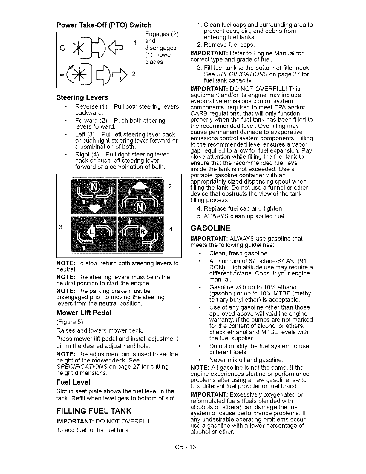
Power Take-Off (PTO) Switch
o
Engages (2)
and
disengages
(1) mower
blades.
Steering Levers
Reverse (1)- Pull both steering levers
backward.
Forward (2) - Push both steering
levers forward.
Left (3) - Pull left steering lever back
or push right steering lever forward or
a combination of both.
Right (4) - Pull right steering lever
back or push left steering lever
forward or a combination of both.
NOTE: To stop, return both steering levers to
neutral.
NOTE: The steering levers must be in the
neutral position to start the engine.
NOTE: The parking brake must be
disengaged prior to moving the steering
levers from the neutral position.
Mower Lift Pedal
(Figure 5)
Raises and lowers mower deck.
Press mower lift pedal and install adjustment
pin in the desired adjustment hole.
NOTE: The adjustment pin is used to set the
height of the mower deck. See
SPECIFICATIONS on page 27 for cutting
height dimensions.
Fuel Level
Slot in seat plate shows the fuel level in the
tank. Refill when level gets to bottom of slot.
FILLING FUEL TANK
IMPORTANT: DO NOT OVERFILL!
To add fuel to the fuel tank:
1. Clean fuel caps and surrounding area to
prevent dust, dirt, and debris from
entering fuel tanks.
2. Remove fuel caps.
IMPORTANT: Refer to Engine Manual for
correct type and grade of fuel.
3. Fill fuel tank to the bottom of filler neck.
See SPECIFICATIONS on page 27 for
fuel tank capacity.
IMPORTANT: DO NOT OVERFILL! This
equipment and/or its engine may include
evaporative emissions control system
components, required to meet EPA and/or
CARB regulations, that will only function
properly when the fuel tank has been filled to
the recommended level. Overfilling may
cause permanent damage to evaporative
emissions control system components. Filling
to the recommended level ensures a vapor
gap required to allow for fuel expansion. Pay
close attention while filling the fuel tank to
ensure that the recommended fuel level
inside the tank is not exceeded. Use a
portable gasoline container with an
appropriately sized dispensing spout when
filling the tank. Do not use a funnel or other
device that obstructs the view of the tank
filling process.
4. Replace fuel cap and tighten.
5. ALWAYS clean up spilled fuel.
GASOLINE
IMPORTANT: ALWAYS use gasoline that
meets the following guidelines:
Clean, fresh gasoline.
A minimum of 87 octane/87 AKI (91
IRON). High altitude use may require a
different octane. Consult your engine
manual.
Gasoline with up to 10% ethanol
(gasohol) or up to 10% MTBE (methyl
tertiary butyl ether) is acceptable.
Use of any gasoline other than those
approved above will void the engine
warranty. If the pumps are not marked
for the content of alcohol or ethers,
check ethanol and MTBE levels with
the fuel supplier.
Do not modify the fuel system to use
different fuels.
Never mix oil and gasoline.
NOTE: All gasoline is not the same. If the
engine experiences starting or performance
problems after using a new gasoline, switch
to a different fuel provider or fuel brand.
IMPORTANT: Excessively oxygenated or
reformulated fuels (fuels blended with
alcohols or ethers) can damage the fuel
system or cause performance problems. If
any undesirable operating problems occur,
use a gasoline with a lower percentage of
alcohol or ether.
GB - 13
Page 14

Fuel Stabilizer
Gasoline left in the fuel system for extended
periods without a stabilizer will deteriorate,
resulting in gum deposits in the system.
These deposits can damage the carburetor
and the fuel hoses, filter and tank. Prevent
deposits from forming in the fuel system
during storage by adding a quality fuel
stabilizer to the fuel. Follow the
recommended mix ratio found on the fuel
stabilizer container.
STOPPING IN AN EMERGENCY
WARNING: Operating unit on
slopes may lead to loss of
steering control. When operating
on slopes be prepared to react to
an emergency situation.
1. Return steering levers to neutral position
2. Immediately set parking brake
3. Turn off PTO and engine
NOTE: This unit is not equipped with the
return to neutral function. The control arms
must be manually brought back to neutral
from the forward position.
STARTING AND SHUTTING OFF
ENGINE
Starting the Engine
NOTE: Disengage the PTO, place the
steering levers in neutral, and engage the
parking brake prior to starting the engine.
1. If the engine is cold, move the choke
control to the On position. If the engine
is warm or hot, do not use choke.
IMPORTANT: DO NOT operate starter for
more than 10 seconds per minute as damage
can occur.
2. Put the ignition key in the switch and
turn it to the Start position.
3. As soon as the engine starts, release the
key.
4. Move the choke control to the Off
position from the Choke position. Wait
until the engine is running smoothly
before operation.
IMPORTANT: Let the engine warm up
several seconds to several minutes
depending on outside temperature.
Stopping the Engine
1. Stop unit.
2. Disengage PTO.
3. Set throttle lever to slow.
4. Turn ignition switch to off position and
remove key.
5. Set parking brake.
OPERATING MOWER
1. Start engine.
2. Set throttle lever to fast.
IMPORTANT: Never engage PTO if mower is
plugged with grass or other material.
3. Engage PTO to start mower blades. It
will take 2-3 seconds for the blades to
engage.
NOTE: The parking brake must be
disengaged prior to moving the steering
levers from the neutral lockout position.
4. Release parking brake.
5. Use steering levers to move the unit.
6. Disengage PTO to stop mower blades.
TRANSPORTING UNIT
ALWAYS shut off engine, set parking brake,
remove key, and properly remove fuel when
transporting unit on a truck or trailer. Tie unit
down securely. Do not tie down by linkages,
guards, cables or other parts that may be
damaged.
GB - 14
Page 15

FOR BEST PERFORMANCE
Cut grass when it is dry.
Keep mower blades sharp.
Keep mower deck properly leveled.
Do not set height of cut too low. For very tall
grass, mow twice.
Do not travel too fast.
Mow with the engine set at full throttle.
When mulching, only remove one-third of
grass length per cutting.
Discharge clippings into areas already cut.
Vary cutting pattern with each mowing.
Do not allow grass or debris to collect inside
of mower deck. Clean after each use.
MOVING UNIT MANUALLY
WARNING: DO NOT disengageor bypass transmission and coast
downhill.
Pull the bypass lever out and lock it in place,
and then release the parking brake to push
the unit by hand.
Push the bypass lever in to drive the unit
normally.
NOTE: There are two bypass levers; one on
each side of the unit.
1. Bypass lever pulled out to push
the unit by hand.
2. Bypass lever pushed in to drive
the unit.
Figure 5
GB- 15
Page 16

_l,]_i __Jl:l
,_ WARNING: AVOID INJURY. Readand understand the entire Safety
section before proceeding.
IMPORTANT: Proper maintenance can
prolong the life of unit. The following chart
shows the recommended service schedule.
Refer to the maintenance instructions in the
Engine Manual for additional information.
NOTE: To have full access to the engine, the
seat must be tipped forward (see TIPPING
SEAT FORWARD on page 17) and the hood
opened (see MOWER DECK REMOVAL
AND INSTALLATION on page 18).
Interval Task _,ction
Check
Safety ,_
Interlock
System
WARNING: Safety interlock system failure and improper
operation of unit can result in death or serious injury. Test
this system each time the unit is operated. If this system
does not function as described, do not operate until repairs
are made (see Safety Interlock System on page 12).
Check Engage parking brake and engage transmission bypass lever (see
Parking MOVING UNIT MANUALLY on page 15). Push unit. If unit rolls, contact
Brake your Ariens Dealer.
Clean Unit Clean engine, battery, seat, mower deck, etc. of all dirt and debris. Do
not use solvents, hard cleaners, or abrasives.
NOTE: Protect painted surfaces with automotive type wax.
IMPORTANT: Do not spray the unit with water, especially when the unit
is warm from operation. Water can seep into bearings and damage
them.
Check
Tires
See SPECIFICATIONS on page 27 for correct tire pressure.
Each Use
CAUTION: Avoid injury! Explosive separation of tire and rim
parts is possible when they are serviced incorrectly:
•Do not attempt to mount a tire without the proper equipment
and experience to perform the job.
Do not inflate the tires above the recommended pressure.
Do not weld or heat a wheel and tire assembly. Heat can cause
an increase in air pressure resulting in an explosion. Welding
can structurally weaken or deform the wheel.
Do not stand in front or over the tire assembly when inflating.
Use a clip-on chuck and extension hose long enough to allow
you to stand to one side.
Check Check for worn or damaged mower blades (see SHARPENING
Mower MOWER BLADE on page 20).
Blades
Follow
Engine
Manual
Mainten-
ance
Schedule
Perform scheduled engine maintenance.
Refer to Engine Manual for detailed
instructions.
NOTE: To drain the oil, remove oil drain
cap and attach the oil drain hose,
supplied in the lit pack, to the drain plug.
Rotate the drain to the left to allow oil to
drain. Turn the drain to the right to close.
Oil Drain Plug
GB - 16
Page 17

Interval Task _,ction
25 Hours
or Every
Season
50 Hours
or Every
Season
100 Hours
or Every
Season
Check
Battery
Keep battery and battery terminals clean (see Cleaning Battery and
Battery Cables on page 21).
UnitLubricatefrontApplygreaset°zerk (1)oneachwheel _ 1
Check Check mower blade mounting hardware and all other fasteners.
Fasteners Replace fasteners that are missing or damaged. Tighten all nuts and
bolts to the correct torque values.
Check All
Belts
Replace worn or deteriorated belts.
Check hydrostatic belt (see REPLACING HYDROSTATIC BELT
on page 24 for hydrostatic belt location).
Check PTO belt (see REPLACING PTO BELT on page 23 for
PTO belt location).
Check All Replace worn or improperly functioning PTO cables.
Cables
[,._o]=l r_,1#Im]r_,1m]l[l_ll / tv_I=1#III[€]
WARNING: AVOID INJURY.
Read and understand the entire
Safety section before proceeding.
TIPPING SEAT FORWARD
Put steering levers up and tip seat forward
(figure 6).
1. Seat Tipped Forward
2. Mounting Hardware
Figure 6
SEAT ADJUSTMENT
1. Tip the seat forward.
2. Loosen mounting hardware and slide
seat forward or backward to desired
position. Tighten mounting hardware
(figure 6).
3. Tip seat back.
GB - 17
Page 18
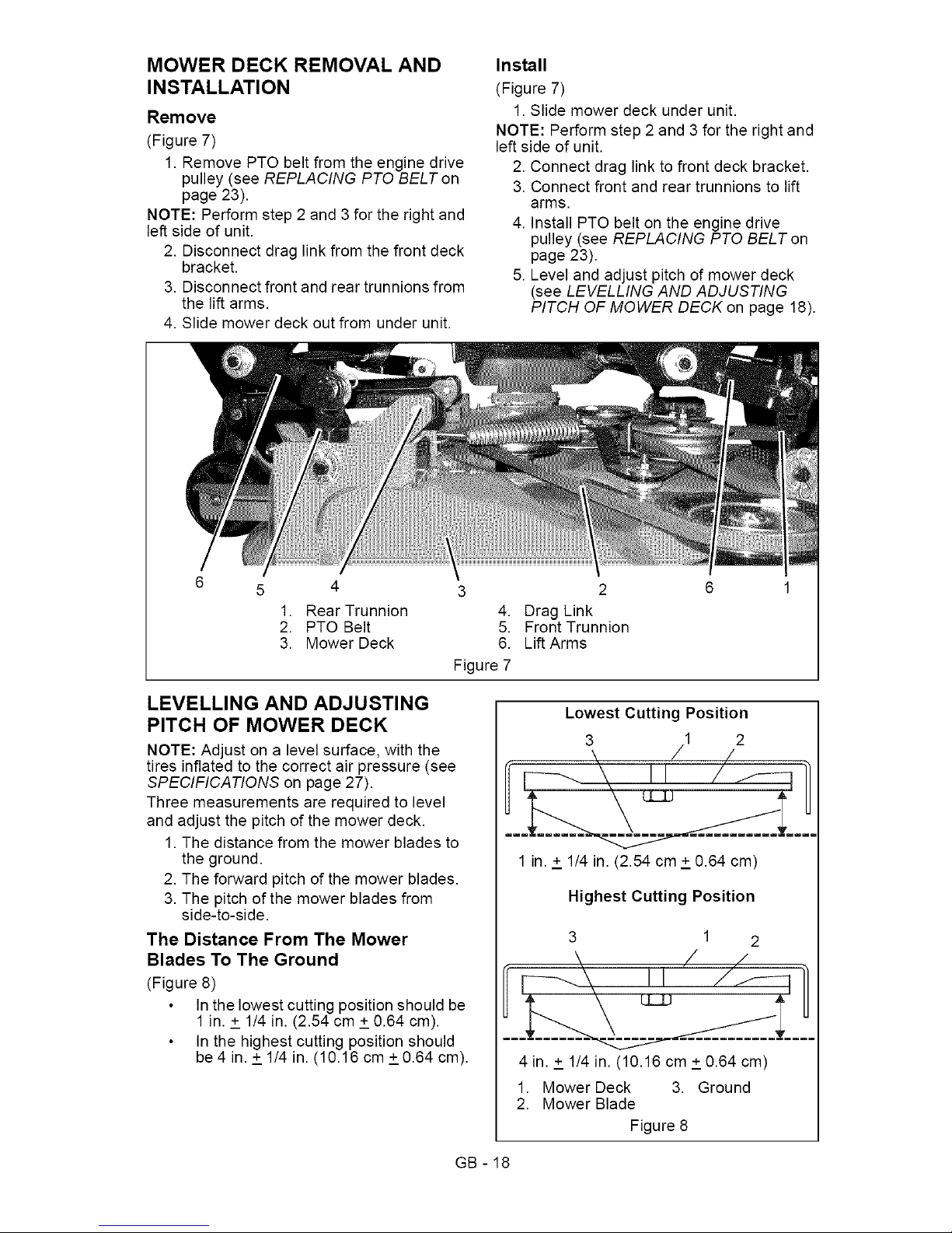
MOWER DECK REMOVAL AND
INSTALLATION
Remove
(Figure 7)
1. Remove PTO belt from the engine drive
pulley (see REPLACING PTO BELT on
page 23).
NOTE: Perform step 2 and 3 for the right and
left side of unit.
2. Disconnect drag link from the front deck
bracket.
3. Disconnect front and rear trunnions from
the lift arms.
4. Slide mower deck out from under unit.
Install
(Figure 7)
1. Slide mower deck under unit.
NOTE: Perform step 2 and 3 for the right and
left side of unit.
2. Connect drag link to front deck bracket.
3. Connect front and rear trunnions to lift
arms.
4. Install PTO belt on the engine drive
pulley (see REPLACING PTO BELT on
page 23).
5. Level and adjust pitch of mower deck
(see LEVELLING AND ADJUSTING
PITCH OF MOWER DECK on page 18).
5 4
1. Rear Trunnion
2. PTO Belt
3. Mower Deck
3
4.
5.
6.
Figure 7
2
Drag Link
Front Trunnion
Lift Arms
LEVELLING AND ADJUSTING
PITCH OF MOWER DECK
NOTE: Adjust on a level surface, with the
tires inflated to the correct air pressure (see
SPECIFICATIONS on page 27).
Three measurements are required to level
and adjust the pitch of the mower deck.
1. The distance from the mower blades to
the ground.
2. The forward pitch of the mower blades.
3. The pitch of the mower blades from
side-to-side.
The Distance From The Mower
Blades To The Ground
(Figure 8)
In the lowest cutting position should be
1 in. + 1/4 in. (2.54 cm + 0.64 cm).
In the highest cutting position should
be4 in. + 1/4 in. (10.16 cm +0.64 cm).
Lowest Cutting Position
3 1 2
\, / /
\ U /f-q
..
1 in. + 1/4 in. (2.54 cm + 0.64 cm)
Highest Cutting Position
3 1 2
k / /
fl I! " />-ql]
4 in. + 1/4 in. (10.16 cm +0.64 cm)
1. Mower Deck 3. Ground
2. Mower Blade
Figure 8
GB - 18
Page 19

The Forward Pitch Of The Mower
Blades
(Figure 9)
Should be 0.0 in. (0.0 mm) to 1/4 in.
(6.35 mm) pitched forward.
NOTE: This measurement must be taken
when the mower blades ends point forward.
Forward Pitch of Mower Blades
3 1 2
\ / /
1
Front of
Mower Deck
1. Mower Deck 3. Ground
2. Mower Blade
Figure 9
The Pitch Of The Mower Blades From
Side-To-Side
(Figure 10)
Should be within 1/4 in. (6.35 mm) as
measured on each side of the mower
deck.
NOTE: This measurement must be taken
when the mower blade ends point left and
right.
Side-To-Side Pitch
1
2
3 / /
\ /
ti / J---ll)
1/4-in. (6.35 mm) from Side-To-Side
1. Mower Deck 3. Ground
2. Mower Blade
Figure 10
Adjusting The Mower Deck To Adjust
Mower Blade Height And Pitch
(Figure 11)
NOTE: Adjusting the mower deck will adjust
the height and pitch of the mower blades.
1. Adjust the trunnions first and re-take the
three measurements required to level
and adjust the pitch of the mower deck.
These measurements are:
a. The distance from the mower
blades to the ground.
b. The forward pitch of the mower
blades.
c. The pitch of the mower blades
from side-to-side.
2. Repeat step 1 as needed until all three
measurements are within the tolerances
specified.
1. Trunnion 2. Mower Deck
Figure 11
REPLACING MOWER BLADE
Remove
(Figure 12)
CAUTION: Mower blades are
sharp and can cut you. Wrap
the blades or wear gloves, and
use extra caution when
servicing them.
1. Block mower blades to prevent rotation.
2. Remove mounting hardware and mower
blades from spindles.
Install
(Figure 12)
1. Install mower blades on spindles with
mounting hardware.
2. Torque 5/8-inch nut to 92 to 130 Ibf-ft
(125 to 176 N°m).
GB - 19
Page 20

j4
1.Spindle
2. Blade
3. Washer
4. 5/8in.Nut
Figure12
SHARPENING MOWER BLADE
CAUTION: DO NOT sharpen
mower blade while on unit. An
unbalanced mower blade will
cause excessive vibration and
eventual damage to unit. Check
mower blade balance prior to
reinstalling mower blades.
NEVER weld or straighten mower
blades.
1. Remove mower blade from unit (see
REPLACING MOWER BLADE on
page 19).
Ariens recommends having mower blades
sharpened by a professional. Contact your
Ariens dealer.
Discard mower blade if (figure 13):
more than 1/2 in. (1.27 cm) of metal is
removed.
the air lift erosion area is eroded.
the mower blade is bent or broken.
Do not change angle of cutting edge or round
the corner at the end of mower blade.
2. Sharpen mower blade by removing an
equal amount of material from each end
of mower blade.
3. Check mower blade balance by sliding
mower blade on an unthreaded bolt. If
blade is balanced, it should remain in a
horizontal position. If either end of
mower blade moves downward, sharpen
the heavy end until mower blade is
balanced.
4. Install mower blade on unit (see
REPLACING MOWER BLADE on
page 19).
DO NOT Sharpen to this Pattern
Sharpen to this Pattern
1/2 in. /
(1/27 cm) 2
1
1. Air Lift Erosion
2. Cutting Edge
Figure 13
SERVICING THE BATTERY
NOTE: Unit comes equipped with a
maintenance-free battery that requires no
regular maintenance except cleaning the
terminals.
,_ WARNING: Battery posts,
terminals and related accessories
contain lead and lead
compounds, chemicals known to
the State of California to cause
cancer and reproductive harm.
Wash hands after handling.
Battery Removal and Installation
Remove
(Figure 14)
1. Tip seat forward (see TIPPING SEAT
FORWARD on page 17).
2. Disconnect negative (-) cable first, then
positive (+) cable.
3. Remove battery hold-down bracket and
battery from unit.
GB - 20
Page 21

Install
(Figure 14)
1. Install battery on the unit with battery
hold-down bracket.
2. Connect positive (+) cable first, then
negative (-) cable.
3. Apply petroleum jelly or dielectric grease
to battery cable ends and terminals.
4. Tip seat back (see TIPPING SEAT
FORWARD on page 17).
2 3 4
1. Positive (+) Terminal
2. Positive (+) Cable
3. Battery Hold-Down Bracket
4. Battery
5. Negative (-) Terminal
6. Negative (-) Cable
Figure 14
Cleaning Battery and Battery Cables
(Figure 14)
1. Tip seat forward (see TIPPING SEAT
FORWARD on page 17).
2. Disconnect negative (-) cable first, then
positive (+) cable.
3. Clean battery cable ends, negative (-)
terminal, and positive (+) terminal with a
wire brush and rinse with a weak baking
soda solution.
4. Connect positive (+) cable first, then
negative (-) cable.
5. Apply petroleum jelly or dielectric grease
to battery cable ends and terminals.
6. Tip seat back (see TIPPING SEAT
FORWARD on page 17).
Charging the Battery
(Figure 14)
WARNING: FROZEN
BATTERIES CAN EXPLODE and
result in death or serious injury.
DO NOT charge a frozen battery.
Let the battery thaw before
charging.
Follow First Aid directions for contact with
battery fluid.
External Contact: Flush with water.
Eyes: Flush with water for at least 15
minutes and get medical attention
immediately!
Internal Contact: Drink large quantities
of water. Follow with Milk of Magnesia,
beaten egg or vegetable oil. Get
medical attention immediately!
In case of internal contact, DO NOT
induce vomiting!
IMPORTANT: DO NOT fast charge. Charging
at a higher rate will damage or destroy
battery.
IMPORTANT: ALWAYS follow information
provided on battery and battery charger.
Contact battery and battery charger
manufacturers' for detailed instructions.
1. Remove battery from unit (see Battery
Removal and Installation on page 20).
2. Place battery in a well-ventilated area.
3. Connect positive (+) lead of charger to
positive (+) terminal, and negative (-)
lead of charger to negative (-) terminal.
4. Charge battery according to battery
charger and battery manufacturers'
instructions.
5. Install battery on unit (see Battery
Removal and Installation on page 20).
Jump-Starting
Ariens does not recommend jump-starting
your unit. Jump-starting can damage engine
and electrical system components. See your
engine manual for more detailed information.
GB - 21
Page 22

ADJUSTING STEERING LEVERS
(Figure 15)
Adjustment 3 Adjustment 1
Adjustment 2
1. Handlebar
2. Upper Control Arm
3. Adjustment Holes
4. Eccentric Spacer
5. Mounting Hardware
6. Lower Control Arm
Figure 15
IMPORTANT: Adjust each steering lever
equally.
NOTE: When adjusting steering levers for the
first time it is recommended that you make
adjustments in the following order.
1. Adjust Steering Lever Height
1. Remove mounting hardware that
attaches the handlebars to the upper
control arm. Move handlebar up or down
until the handlebar mounting holes are
aligned with the prefered adjustment
holes.
2. Install mounting hardware and tighten.
2. Adjust Steering Lever Width
1. Loosen hardware at the base of the
lower control arm item 5.
2. Rotate eccentric spacer to move the
levers away from or closer to the
operators position (figure 16).
Rotate this end away from the the operator
position to move the steering levers in.
Rotate this end away from the operator
position to move the steering levers out.
Figure 16
3. Adjust Steering Lever Forward or
Backward
1. Loosen, do not remove, the bolts
securing the handlebar to the upper
control arm.
2. Slide steering lever forward or backward
to desired position and tighten bolts.
NOTE: Tigthen upper bolt first.
Forward Speed Adjustment
(Figure 17)
NOTE: Reverse speed cannot be adjusted. If
unit tracks excessively left or right in reverse,
see your Dealer for repair.
IMPORTANT: The unit should track within
2 feet (0.61 m) of a straight line for 30 feet
(9.14 m).
The travel of the steering levers may need
adjustment if the unit turns to the right or left
when both steering levers are pushed as far
forward as possible.
NOTE: The side the unit turns toward
indicates that the wheel on that side is turning
slower than the other wheel. Either the wheel
that is turning faster needs to slow down or
the wheel that is turning slower needs to
speed up to allow the unit to travel in a
straight line.
1. Determine which way the unit turns.
2. Loosen jam nut on the adjustment bolt.
3. Adjust speed by:
Turning adjustment bolt clockwise to
decrease steering lever travel.
Turning adjustment bolt
counterclockwise to increase steering
lever travel.
4. Tighten the jam nut.
GB - 22
Page 23

1
1. ForwardTravelAdjustmentBolt
2. LowerControlArm
Figure17
REPLACING PTO BELT
Remove
(Figure 18)
1. Lower mower deck to the ground.
2. Remove belt covers from mower deck.
CAUTION: Use care when
releasing idler spring tension.
Keep body parts well away from
idler when performing this
operation.
3. Pull idler arm towards outside of unit
until tension is removed from PTO belt.
4. Remove PTO belt from left mower deck
pulley.
5. Slowly release idler arm until tension is
removed from idler spring.
6. Remove PTO belt from mower deck and
engine drive pulley.
915157,169
1
1. Deck Spindle
2. Engine Drive Pulley
3. Deck Idler
4. PTO Belt
Figure 18
915159, 161,171
4
1. Deck Spindle
2. Engine Drive Pulley
3. Deck Idler
4. PTO Belt
Figure 19
Install
(Figure 18)
NOTE: Do not install PTO belt on left mower
deck pulley in step 1.
1. Install PTO belt on engine drive pulley
and mower deck.
2. Pull idler arm towards outside of unit
until PTO belt can be routed around left
mower deck pulley.
GB - 23
Page 24

3.Slowlyreleaseidlerarmuntilidlerpulley
restsfirmlyagainstPTObelt.
4.Installbeltcoversonmowerdeck.
NOTE:Ensurethatbeltisstillpositionedin
thegrooveofthesheaveafterbeltcoversare
installed.
REPLACING HYDROSTATIC BELT
Remove
(Figure 20)
1. Remove PTO belt (see REPLACING
PTO BELT on page 23).
CAUTION: Use care when
releasing idler spring tension.
Keep body parts well away from
idler when performing this
operation.
2. Disconnect idler spring.
3. Remove hydrostatic belt from
hydrostatic transmission pulleys, drive
pulley, and idler.
Install
(Figure 20)
1. Install hydrostatic belt on idler, drive
pulley, and hydrostatic transmission
pulleys.
2. Connect idler spring.
3. Install PTO belt (see REPLACING PTO
BELT on page 23).
4
1
\
1. Hydrostatic Belt 3. Idler
2. Hydrostatic 4. Idler Spring
Transmission
Pulley
Figure 20
[,,,,"]i_o_e-] :1
Short Term Storage
IMPORTANT: NEVER clean unit with high-
pressure water or store unit outdoors.
Remove all dirt, grease, leaves, etc. Store in
a clean dry area.
Inspect unit for signs of wear or damage.
Ensure all fasteners are properly tightened.
Long Term Storage
Follow all instructions under Short Term
Storage,
Remove and fully charge battery. Store in a
clean dry area.
Refer to Engine Manual for the proper engine
storage procedures.
Touch up all scratched or chipped paint
surfaces.
Fuel System
Gasoline left in the fuel system for extended
periods without a stabilizer will deteriorate,
resulting in gum deposits in the system.
These deposits can damage the carburetor
and the fuel hoses, filter and tank. Prevent
deposits from forming in the fuel system
during storage by adding a quality fuel
stabilizer to the fuel. Follow the
recommended mix ratio found on the fuel
stabilizer container.
To treat the fuel system for storage:
1. Add fuel stabilizer according to
manufacturers's instructions.
2. Run engine for at least 10 minutes after
adding stabilizer to allow it to reach the
carburetor.
NEVER store the engine with fuel in the fuel
tank inside of a building with potential
sources of ignition.
GB - 24
Page 25

PROBLEM PROBABLE CORRECTION
CAUSE
Enginewill not 1. 1.
crank/start.
Engine runs
rough.
Unit does not
move with
engine running
when using
steering levers.
PTO or mower
blades do not
engage or shut
off.
Engine
overheats.
Safety interlock
system is not
engaged or is
faulty.
2. Fuel tank is
empty.
3. Discharged
battery.
4. Poor connection
between battery
and battery
cables.
5.
Spark plug wire(s)
loose or spark
plug(s) faulty.
6. Faulty electrical
system.
7.
1.
2.
3.
1.
2.
3.
1.
2.
3.
4.
1.
2.
3.
Faulty engine.
Choke engaged.
Airfiltercartridge
plugged.
Faulty engine.
The transmission
bypassleveris
engaged.
Faulty hydrostatic
belt.
Faulty
transmission.
Operator
presence switch
not depressed.
Faulty operator
presence switch.
Faulty PTO belt.
Faulty PTO
switch, wires,
connectors, or
clutch.
Engine oil level
low.
Cooling system
plugged.
Faulty engine.
2.
3.
4.
5.
Check safety interlock system (see Safety
Interlock System on page 12).
Fill fuel tank (see FILLING FUEL TANK on
page 13).
Charge battery (see Charging the Battery
on page 21 ).
Tighten battery cables and/or clean battery
and battery cables (see Cleaning Battery
and Battery Cables on page 21).
Connect spark plug wire(s) or replace spark
plug(s). Refer to Engine Manual for detailed
instructions.
6. Contact your Ariens Dealer.
7. Contact your Ariens Dealer.
1. Disengage choke.
2. Clean or replace air filter cartridge. Refer to
Engine Manual for detailed instructions.
3. Contact your Ariens Dealer.
1. Disengage transmission bypass lever (see
MOVING UNIT MANUALLY on page 15).
2.
3.
1.
2.
3.
4.
1.
2.
3.
Replace hydrostatic belt (see REPLACING
HYDROSTATIC BELT on page 24).
Contact your Ariens Dealer.
Depress operator presence switch by sitting
on seat.
Contact your Ariens Dealer.
Replace PTO belt (see REPLACING PTO
BELT on page 23).
Contact your Ariens Dealer.
Add engine oil. Refer to Engine Manual for
detailed instructions.
Clean cooling system. Refer to Engine
Manual for detailed instructions.
Contact your Ariens Dealer.
GB - 25
Page 26

PROBLEM
Unit moves with
engine off and
parking brake
engaged.
Unit does not
travel in a
straight line.
Unit creeps with
steering levers
in neutral
position.
Poor cutting
quality.
2.
1.
2.
3.
2.
PROBABLE
CAUSE
The parking brake
needs
adjustment.
Faulty parking
brake.
Incorrect tire
pressure.
Steering levers
need adjustment.
Hydrostatic
transmission
and/or linkage
needs
adjustment.
Hydrostatic
transmission
and/or linkage
needs
adjustment.
Mower deck not
level or mower
pitch is incorrect.
Dull or faulty
mower blades.
CORRECTION
1. Contact your Ariens Dealer.
2. Contact your Ariens Dealer.
1.
2.
3.
Check tire pressure (see SPECIFICATIONS
on page 27).
Adjust steering levers (see Forward Speed
Adjustment on page 22)
Contact your Ariens Dealer.
1. Contact your Ariens Dealer.
2.
Level and adjust pitch of mower deck (see
LEVELLING AND ADJUSTING PITCH OF
MOWER DECK on page 18).
Sharpen mower blades (see SHARPENING
MOWER BLADE on page 20) or replace
mower blades (see REPLACING MOWER
BLADE on page 19).
[.,,-._o,]:11 _7__I_ K,,,.-_ P_'T__o];_[_,,,,_
Be sure to always use genuine Ariens
parts to kee your unit running like new.
Part No. Description
51519500 34- and 50-Inch Spindle
Assembly
51520900 42-Inch Spindle Assembly
07100801 Front Wheel (Tread)
07100124 Front Wheel (Smooth)
07200116 34-Inch Deck Belt
07200010 HA Raw Laminated Belt -
Hydraulic Drive
03971900 34-Inch Mower Blade
03797300 34-Inch Mulching Blade
04265400 42-Inch Mower Blade
07200523 42-Inch Deck Belt
03971900 50-Inch Mower Blade
07200524 50-Inch Deck Belt
See your authorized Ariens dealer to add
these optional accessories to your unit.
Part No. Description
71503300 36-Inch Roller
71503400 48-Inch Dethatcher
71503600 Spreader
71508200 48-Inch Aerator
71510800 34-Inch Mulch Kit
71510900 Trailer Hitch Kit
81503700 34-Inch Non-Powered Bagger
81503800 42-Inch Non-Powered Bagger
81503900 50-Inch Non-Powered Bagger
71512000 42-Inch Mulch Kit
71511900 50-Inch Mulch Kit
GB - 26
Page 27

[,,,,___o]_,,,_
915157 915159 915161
Zoom 34 Zoom 42 Zoom 50
Model Number
Model
Engine
Type
Engine Displacement in.3 (cc)
Governed RPM (May be different
from maximum RPM)
Drive
Forward Max. - m.p.h (km/h)
Reverse Max. - m.p.h (km/h)
Briggs & Stratton Kohler Kohler
30.51 (500) 44 (725) 44 (725)
3600 + 0
3600 - 100
6.0 (9.6)
3.0 (4.8)
Turning Radius Zero
Brakes Internal Transmission
Transmission Hydrostatic Drive
Electrical
Starter Electric
Battery 12V Maintenance Free SLI U1B 275
PTO (Power Take-Off) Electric Clutch
Fuel
Fuel Type Refer to Engine Manual
Fuel Tank Capacity - gal. (L) 1.97 (7.49)
Size and Weight
Length - in. (cm) 65 (165.1)
Width -in. (cm) 45 (114.3) 54 (137.2) 62 (157.5)
Weight -Ibs (kg) 405 (183.7) 415 (188.2) 490 (222.3)
Height- in. (cm) 40 (102) 42 (106.7)
Tires
Front Tire Size - in. 4 x 11
Rear Tire Size - in. 18x6.5x8 18xS.5x8 18x9.5x8
Front Tire Pressure- psi (kPa) 46 (317)
Rear Tire Pressure - psi (kPa) 10 (68.95)
Mower Deck
Cutting Height- in. (cm) 1-4 (2.54- 10.16)
Cutting width -in. (cm) 34 (86) 42 (106.7) 50 (127)
Max. Towing Capacity- Ibs (kg) 300 (136)
Max. Tongue Weight - Ibs (kg) 30 (13.6)
GB - 27
Page 28

[,,,,___o]_,,,_
Model Number
Model
Engine
Type
Engine Displacement in.3 (cc)
Governed RPM (May be different
from maximum RPM)
Drive
Forward Max. - m.p.h (km/h)
Reverse Max. - m.p.h (km/h)
Turning Radius
Brakes
Transmission
Electrical
Starter
Battery
915169
Zoom 34 CARB
915171
Zoom 42 CARE}
Briggs & Stratton Kohler
30.51 (500) 44 (725)
3600 + 0
3600 - 100
6.0 (9.6)
3.0 (4.8)
Zero
Internal Transmission
Hydrostatic Drive
Electric
12V Maintenance Free
SLI U1B 275
PTO (Power Take-Off) Electric Clutch
Fuel
Fuel Type Refer to Engine Manual
Fuel Tank Capacity - gal. (L) 1.97 (7.49)
Size and Weight
Length - in. (cm) 65 (165.1)
Width -in. (cm) 45 (114.3) 54 (137.2)
Weight -Ibs (kg) 405 (183.7) 415 (188.2)
Height - in. (cm) 40 (102)
Tires
Front Tire Size - in. 4 x 11
Rear Tire Size - in. 18 x 6.5 x 8 18 x 8.5 x 8
Front Tire Pressure - psi (kPa) 46 (317)
Rear Tire Pressure - psi (kPa) 10 (68.95)
Mower Deck
Cutting Height - in. (cm) 1.5 - 4.5 1 - 4 (2.54 - 10.16)
(3.8- 11.4)
Cutting width - in. (cm) 34 (86) 42 (106.7)
Max. Towing Capacity- Ibs (kg) 300 (136)
Max. Tongue Weight - Ibs (kg) 30 (13.6)
GB - 28
Page 29

COMPANY
Two-Year Limited Lawn and
Garden Consumer Ride-On
Warranty
Ariens Company warrants to the original purchaser that Ariens, Gravely and Countax brand consumer
products manufactured and sold by Ariens Company will be free from defects in material and workmanship
for a period of two years after the date of purchase. An authorized Ariens dealer (Ariens brand products),
Gravely dealer (Gravely brand products), or Countax dealer (Countax brand products) will repair any defect
in material or workmanship, and repair or replace any defective part, subject to the conditions, limitations and
exclusions set forth herein. Such repair or replacement will be free of charge (labor and parts) to the original
purchaser except as noted below.
Five-Year Limited Warranty on Mower Deck Shell
The deck shell on zero-turn riding mowers is warranted to the original purchaser for five years from
the date of purchase. Any defect in material or workmanship of the deck shell will be repaired free of
charge (parts and labor) to the original purchaser for two years after the date of purchase. For the third
through fifth year from the date of purchase, the parts required to repair a defect in material or work-
manship of the deck shell, not the labor, will be provided free of charge.
Five-Year Limited Warranty on Main Frame
The main frame on zero-turn riding mowers is warranted to the original purchaser for five years from
the date of purchase. Any defect in material or workmanship of the main frame will be repaired free of
charge (parts and labor) to the original purchaser for two years after the date of purchase. For the third
through fifth year from the date of purchase, the parts required to repair a defect in material or work-
manship of the main frame, not the labor, will be provided free of charge.
Two-Year Limited Warranty on AMP TM Series Battery Packs and Subassembfies
The battery pack and/or battery subassemblies on AMP series electric riding mowers is/are warranted to the
original purchaser for two years from the date of purchase. Ariens Company will replace, free of charge to
the original purchaser, any battery pack and/or battery subassembly that fails due to defect in material or
workmanship for one year after the date of purchase. For the next 12 months, Ariens Company will cover the
prorated cost of replacing a battery pack and/or battery subassembly that fails due to defect in material or
workmanship. This warranty does not apply to battery packs or battery subassemblies that fail due to acci-
dent, neglect, abuse, improper maintenance, improper storage or improper charging procedures.
90-Day Limited Warranty on Service Parts and Accessories
Genuine Ariens, Gravely or Countax brand service parts and accessories are warranted to be free from
defects in material and workmanship for a period of 90 days after the date of purchase. An authorized
Ariens, Gravely or Countax dealer will repair or replace any such part or accessory free of charge,
except for labor, during that period.
The duration of all warranties herein applies only if the product is put to personal use around a household or
residence. If the product is put to any business use, agricultural, commercial, or industrial, then the duration
of these warranties shall be 90 days after the date of purchase. For Ariens Max Zoom and Gravely ZT HD
models put to commercial use, the duration of these warranties, except for service parts and accessories, is
one year from the date of purchase.
If any product is rented or leased, then the duration of these warranties shall be 90 days after the date of
purchase,
Exceptions, Limitations, Exclusions
Customer Responsibilities
Register the product immediately at the time of sale. If the dealer does not register the product, the
customer must complete the product registration card in the literature package and return it to the Ariens
Company, or register the unit online at wwv.ariens.com, www.gravely.com, wv_v.countax.com.
To obtain warranty service, the original purchaser must:
Perform the maintenance and minor adjustments explained in the owner's manual.
Promptly notify Ariens Company or an authorized Ariens, Gravely or Countax service representative of
the need for warranty service.
Transport the product to and from the place of warranty service.
Have the warranty service performed by an authorized Ariens, Gravely or Countax service
representative.
_,_'/_ Con_Ride_2011
Company 29
Page 30

To find an Ariens or Gravely authorized service representative, contact Ariens in the United States, Canada
or Mexico at:
655 W. Ryan Street
Brillion, WI 54110
(g20) 756- 4688
www.ariens.com
www.gravely.com
To find a Countax authorized service representative, contact Countax in Europe or Australia at:
Countax Ltd
Countax House
Great Haseley
Oxfordshire
OX44 7PF
0800 597 7777
www.countax.com
Exceptions and Limitations
Batteries are warranted only for a period of 12 months after date of purchase, on a prorated basis. For
the first 90 days of the warranty period, a defective battery will be replaced free of charge. If the
applicable warranty period is more than 90 days, Ariens Company will cover the prorated cost of any
defective battery, for up to 12 months after the date of purchase. This battery limited warranty does not
apply to the battery packs on AMP series products.
Exclusions - Items Not Covered by This Warranty
Engines and engine accessories are covered only by the engine manufacturer's warranty and are not
covered by this warranty.
Parts that are not genuine Ariens, Gravely or Countax service parts are not covered by this warranty.
The following maintenance, service and replacement items are not covered by this warranty unless
they are noted in the Limitations section above: lubricants, spark plugs, oil, oil filters, air filters, fuel
filters, brake linings, brake arms, brake shoes, runners, scraper blades, shear bolts, mower blades,
mower vanes, headlights, light bulbs, knives, cutters.
Any misuse, alteration, improper assembly, improper adjustment, neglect, or accident which requires
repair is not covered by this warranty.
Disclaimer
Ariens Company may from time to time change the design of its products. Nothing contained in this warranty
shall be construed as obligating the Ariens Company to incorporate such design changes into previously
manufactured products, nor shall such changes be construed as an admission that previous designs were
defective.
LIMITATION OF REMED Y A ND DAMA GES
Ariens Company's liability under this warranty, and under any implied warranty that may exist, is limited to
repair of any defect in workmanship, and repair or replacement of any defective part. Ariens Company shall
not be liable for incidental, special, or consequential damages (including lost profits). Some states do not
allow the exclusion of incidental or consequential damages, so the above limitation or exclusion may not
apply to you.
DISCLAIMER OF FURTHER WARRANTY
Ariens Company makes no warranty, express or implied, other than what is expressly made in this
warranty. If the law of your state provides that an implied warranty of merchantability, or an implied
warranty of fitness for particular purpose, or any other implied warranty, applies to Ariens Company,
then any such implied warranty is limited to the duration of this warranty. Some states do not allow
limitations on how long an implied warranty lasts, so the above limitation may not apply to you.
This warranty gives you specific legal rights, and you may also have other rights which
vary from region to region.
__ Con_Ride_2011
Company 3o
Page 31
CALIFORNIA AND EPA (UNITED STATES ENVIRONMENTAL
PROTECTION AGENCY) EVAPORATIVE EMISSION CONTROL
WARRANTY STATEMENT
YOUR WARRANTY RIGHTS AND OBLIGATIONS
The CARB (California Air Resources Board), the EPA, and Ariens Company are pleased to explain the
evaporative emission control system's warranty on your 2011 model year small off-road equipment. In
California, new equipment that uses small off-road engines must be designed, built, and equipped to
meet the State's stringent anti-smog standards. Ariens Company must warrant the evaporative
emission control system on your small off-road equipment for the period listed below provided there
has been no abuse, neglect or improper maintenance of your equipment.
Your evaporative emission control system may include parts such as: fuel tanks, fuel lines, fuel caps,
valves, canisters, filters, vapor hoses, clamps, connectors, and other associated components.
MANUFACTURER'S WARRANTY COVERAGE:
This evaporative emission control system is warranted for two years. If any evaporative
emission-related part on your equipment is defective, the part will be repaired or replaced by Ariens
Company.
OWNER'S WARRANTY RESPONSIBILITIES:
• As the small off-road equipment owner, you are responsible for the performance of the required
maintenance listed in your Owner's Manual. Ariens Company recommends that you retain all
receipts covering maintenance on your small off-road equipment, but Ariens Company cannot deny
warranty solely for the lack of receipts.
• As the small off-road equipment owner, you should however be aware that the Ariens Company may
deny you warranty coverage if your evaporative emission control system part has failed due to
abuse, neglect, or improper maintenance or unapproved modifications.
• You are responsible for presenting your small off-road equipment to an authorized Ariens, Gravely,
or Parker service representative as soon as the problem exists. The warranty repairs should be
completed in a reasonable amount of time, not to exceed 30 days. If you have a question regarding
your warranty coverage, you should contact Ariens Company Technical Service Center at
1-920-756-4688.
DEFECTS WARRANTY REQUIREMENTS:
(a.) The warranty period begins on the date the small off-road equipment is delivered to an ultimate
purchaser.
(b.) General Evaporative Emissions Warranty Coverage. Ariens Company warrants to the ultimate
purchaser and any subsequent owner that the evaporative emission control system when
installed was:
(1.) Designed, built, and equipped so as to conform with all applicable EPA and CARB
regulations; and
(2.) Free from defects in materials and workmanship that causes the failure of a warranted part
for a period of two years.
(c.) The warranty on evaporative emissions-related parts will be interpreted as follows:
(1.) Any warranted part that is not scheduled for replacement as required maintenance in the
written instructions must be warranted for the warranty period defined in subsection (b)(2).
If any such part fails during the period of warranty coverage, it must be repaired or replaced
by the Ariens Company. Any such part repaired or replaced under the warranty must be
warranted for a time not less than the remaining warranty period.
(2.) Any warranted part that is scheduled only for regular inspection in the written instructions
must be warranted for the warranty period defined in subsection (b)(2). A statement in such
written instructions to the effect of "repair or replace as necessary" will not reduce the
period of warranty coverage. Any such part repaired or replaced under warranty must be
warranted for a time not less than the remaining warranty period.
(3.) Any warranted part that is scheduled for replacement as required maintenance in the
written instructions must be warranted for the period of time prior to the first scheduled
replacement point for that part. If the part fails prior to the first scheduled replacement, the
part must be repaired or replaced by the Ariens Company. Any such part repaired or
replaced under warranty must be warranted for a time not less than the remainder of the
period prior to the first scheduled replacement point for the part.
_'_4&_ Company CARB_EPA_2011
31
Page 32

(4.)Repairorreplacementofanywarrantedpartunderthewarrantyprovisionsofthisarticle
mustbeperformedatnochargetotheowneratanauthorizedAriens,Gravely,orParker
servicerepresentative.
(5.)Notwithstandingtheprovisionsofsubsection(4)above,warrantyservicesorrepairsmust
beprovidedatauthorizedAriens,Gravely,orParkerservicerepresentativesthatare
franchisedtoservicethesubjectsmalloff-roadequipment.
(6.)Theownermustnotbechargedfordiagnosticlaborthatleadstothedeterminationthata
warrantedpartisinfactdefective,providedthatsuchdiagnosticworkisperformedatan
authorizedAriens,Gravely,orParkerservicerepresentative.
(7.)Throughouttheevaporativeemissioncontrolsystem'swarrantyperiodsetoutinsubsection
(b)(2),theAriensCompanymustmaintainasupplyofwarrantedpartssufficienttomeetthe
expecteddemandforsuchparts.
(8.)Manufacturer-approvedreplacementpartsmustbeusedintheperformanceofany
warrantymaintenanceorrepairsandmustbeprovidedwithoutchargetotheowner.Such
usewillnotreducethewarrantyobligationsofthemanufacturerissuingthewarranty.
(9.)Theuseofanyadd-onormodifiedpartswillbegroundsfordisallowingawarrantyclaim
madeinaccordancewiththisarticle.Themanufacturerissuingthewarrantywillnotbe
liableunderthisArticletowarrantfailuresofwarrantedpartscausedbytheuseofan
add-onormodifiedpart.
Evaporative Emission Warranty Parts List
The following parts are considered emission-related components for evaporative emissions:
Fuel Tank, Fue! Cap and Tether
Fuel Line, Fuel Line Fittings, Clamps*
Pressure Relief Valves, Control Valves*
Control Solenoids*, Electronic Controls*
Vacuum Control Diaphragms*
Control Cables*, Control Linkages*
Purge Valves
Vapor Hoses, Liquid/Vapor Separator
Carbon Canister, Canister Mounting Brackets
Carburetor Purge Port Connector
* As related to the evaporative emission control system
Disclaimer
New equipment sold in the state of California that uses small off-road engines must be exclusively
certified and appropriately labeled for sale in California. Some equipment covered by this Owner's
Manual my not be certified for sale in California and the presence of the preceding CARB and EPA
Warranty Statement does not by its existence indicate which, if any, of the equipment covered by this
Owner's Manual may be sold in California.
Some equipment covered by this Owner's Manual may have been manufactured prior to certain
affectivity dates requiring the inclusion of evaporative emission centre! systems. Therefore some
equipment covered by this Owner's Manual may not include the evaporative emission control systems
referred to in the preceding CARB and EPA Warranty Statement.
_'_ Company CARB_EPA_2011
32
Page 33

Ariens Company
655 West Ryan Street
Brillion, WI 54110-1072
920-756-4688
Fax 920-756-2407
www.ariens.com
& WARNING &
The engine exhaust from this product
contains chemicals known to the State
of California to cause cancer, birth
defects or other reproductive harm.
An _4_p_._ Company Brand
Page 34

Zoom @
Manual del propietario/operador
Models
915157 - Zoom 34
915159 - Zoom 42
915161 - Zoom 50
915169 - Zoom 34 CARB
915171 - Zoom 42 CARB
En esta maquina puede utilizarse gasolina con hasta un 10% de etanol (El0) o hasta un 10% de
MTBE (eter de metil butil terciario).
El uso de cualquier otro tipo de gasolina con un porcentaje superior al 10% de etanol (El0) o al
10% de MTBE invalidara la garantia del producto.
,_ _ 03997702B 1/11
ESPANOL Printed in USA
Page 35

rEqi][_ -
SEGURIDAD ...................... 4
MONTAJE ....................... 10
CONTROLES Y
CARACTERiSTICAS ............... 12
FUNCIONAMIENTO ............... 13
PROGRAMA DE MANTENIMIENTO .. 17
REPARACIONES Y AJUSTES ....... 19
ALMACENAMIENTO .............. 27
LOCALIZACION DE AVERiAS ....... 28
PIEZAS DE REPUESTO ............ 30
ACCESORIOS .................... 30
ESPECIFICACIONES .............. 31
GARANTiA ...................... 33
I_//_,_o_]_l
NON-ENGLISH MANUALS
Manuals in languages other than
English may be obtained from your
Dealer. Visit your dealer or
www.ariens.com for a list of
languages available for your
equipment.
Manuals printed in languages other
than English are also available as a
free download on our website:
http://www.ariens.com
MANUALES EN IDIOMAS
DIFERENTES DEL INGLES
Puede obtener manuales en
,_ idiomas diferentes del ingles en su
distribuidor. Visite a su distribuidor
o vaya a www.ariens.com para
obtener una lista de idiomas
-_ disponibles para su equipo.
Tambien puede imprimir manuales
en idiomas diferentes del ingles
descargandolos gratuitamente de
nuestra pagina Web:
http://www.ariens.com
MANUELS NON ANGLAIS
Des manuels dans differentes
langues sont disponibles chez
votre revendeur. Rendez-vous
chez votre revendeur ou allez sur
le site www.ariens.com pour
consulter la liste des langues
disponibles pour votre equipement.
Les manuels imprimes dans des
langues differentes de I'anglais
sont egalement disponibles en
telechargement gratuit sur notre
site Web:
http://www.ariens.com
EL MANUAL
Antes de hacer funcionar la unidad,
lea con atenci6n yen su totalidad los manuales.
El contenido de los manuales le ayudara
a entender las instrucciones y los controles
durante el funcionamiento normal
y el mantenimiento.
Todas las referencias a la izquierda, derecha,
adelante o atras se dan desde laperspectiva del
operario sentado en posici6n de funcionamiento
y orientado en la direcci6n de avance.
MANUAL DEL MOTOR
El motor de esta unidad se trata en un manual
independiente especifico del mismo.
Este manual se incluye en la documentaci6n
entregada junto con la unidad. Consulte este
manual cuando necesite recomendaciones
de mantenimiento del motor. Si no dispone
del manual del motor, p6ngase en contacto
con el fabricante del motor para que
le proporcione uno nuevo.
MODELO Y NUMEROS DE SERIE
AI pedir piezas de repuesto o al realizar
preguntas sobre reparaciones, tenga a mano
los nQmeros de modelo y de serie de la unidad
y del motor.
Los nQmeros estan situados en el formulario
de registro del producto del paquete
de documentaci6n de la unidad. Se hallan
impresos en una etiqueta de nQmero de serie
Iocalizada en la estructura de la unidad debajo
del asiento (figura 1).
E-2
Page 36

EtiquetadelnQmerodeseriedelaunidad
Figura1
AnotaraquielmodeloylosnQmeros
deseriedelaunidad.
Anotaraquielmodelodelmotor
ylosnQmerosdeserie.
REGISTRO DEL PRODUCTO
El concesionario Ariens debera registrar el
producto en el momento de la compra. El
registro del producto ayudara a la compafiia
a procesar las reclamaciones de garantia, asi
como a ponerse en contacto con usted con la
informaci6n de servicio mas reciente. Todas
las reclamaciones que cumplan los requisitos
durante el periodo de garantia limitada seran
aceptadas, independientemente de si se
devuelve o no la tarjeta de registro de producto.
Guarde una prueba de su compra si no registra
su unidad.
Nota para el cliente: Si el concesionario no
registra el producto, rellene, firme y devuelva
la tarjeta de registro del producto a Ariens
o acceda a www.ariens.com en Internet.
PIEZA8 DE REPUESTO
NO AUTORIZADA8
Use Qnicamente piezas de repuesto
de Ariens. La sustituci6n de cualquier pieza
de esta unidad por otra que no sea una pieza
de repuesto autorizada por Ariens puede
afectar negativamente al rendimiento,
durabilidad o seguridad de la unidad, y puede
Ilegar a anular la garantia. Ariens declina
toda responsabilidad por dafios o
reclamaciones, ya sea a la garantia, dafios
materiales, lesiones o incluso la muerte,
provocados por el uso de piezas
de repuesto no autorizadas.
NOTA: Puede descargar un manual de piezas
completo de www.ariens.com en Intemet.
ENTREGA
Nota para el usuario: Si ha comprado este
producto sin montar o sin las instrucciones
completas por parte del vendedor,
es su responsabilidad:
Lea y comprenda todas
las instrucciones de montaje contenidas
en este manual. En el caso de que no
comprenda o tenga dificultad en seguir
las instrucciones, p6ngase en contacto
con el concesionario de Ariens mas
cercano para obtener asistencia.
NOTA: Para encontrar el concesionario Ariens
mas cercano, acuda a www.ariens.com
en Intemet.
,_ iADVERTENCIA7 El montaje
o los ajustes incorrectos pueden
causar lesiones graves.
Antes de intentar poner
en funcionamiento la unidad:
1. Asegurarse de que todo el montaje
se ha realizado correctamente.
2. Comprenda todas las precauciones
de seguridad indicadas en los manuales.
3. Revise las funciones de control y el
funcionamiento de la unidad. No ponga
la unidad en marcha a no ser que todos
los controles funcionen tal y como
se describe en este manual.
4. Repase las recomendaciones referentes
a la lubricaci6n, mantenimiento y ajustes.
5. Repase la p61iza de la garantia limitada.
6. Complete la tarjeta para registrar
el producto y devolverla a Ariens
Company, o bien conectese a
www.ariens.com.
E-3
Page 37

CLAUSULA DE EXENCION
DE RESPONSABILIDAD
Ariens se reserva el derecho a interrumpir,
realizar cambios y aSadir mejoras a los
productos en cualquier momento sin aviso ni
obligaci6n al comprador.
Las descripciones yespecificaciones contenidas
en este manual eran las vigentes en el momento
de su publicaci6n. Algunos equipamientos
descritos en este manual pueden
ser opcionales. Algunas ilustraciones
pueden no aplicar a su unidad.
[,,,"]_e']llJ:,,lImT_,_m]
iADVERTENCIA! Esta maquina de
corte puede amputar manos y pies
y lanzar objetos. Si no observa las
instrucciones de seguridad de los
manuales y las calcomanias podrian
producirse lesiones graves
o incluso la muerte.
Las pendientes son uno de los
factores principales relacionados
con la perdida de control y los
accidentes por vuelco. Preste
especial atenci6n cuando haga
funcionar la unidad en pendientes.
Se pueden producir accidentes
tragicos si el operador no observa
la presencia de menores. No
asuma nunca que los menores
permaneceran en el Qltimo sitio
en el que los vio.
La gasolina es altamente inflamable
y sus vapores son explosivos;
manejela con cuidado.
Desactive el accesorio, detenga
la unidad y el motor, saque la Ilave,
active elfreno de estacionamiento
y deje que todas las partes m6viles
se detengan antes de abandonar
la posici6n del operador.
SiMBOLOS DE SEGURIDAD
Busque estos simbolos
para informarse sobre las
precauciones de seguridad
importantes. Su significado
es el siguiente:
iAtenci6n!
iAfecta a la seguridad
personal!
iEste alerta!
iObedezca el mensaje!
El simbolo de alerta de seguridad se incluye
en las etiquetas adhesivas yen el presente
manual. Lea y comprenda el mensaje relativo
a la seguridad. Contiene informaci6n importante
acerca de la seguridad personal.
,_ iADVERTENCIA!iSITUACION POTENCIALMENTE
PELIGROSA! Si no se evita,
PUEDE RESULTAR en lesiones
graves o la muerte.
_ PELIGNO iSITUACION
DE PELIGRO INMINENTE!
Si no se evita, RESULTARA
en lesiones graves o la muerte.
PRECAUCIONiSITUACI6N
POTENCIALMENTE PELIGROSA!
Si no se evita, PUEDE RESULTAR
en lesiones leves o moderadas.
Tambien puede usarse para alertar
contra practicas no seguras.
NOTACIONE8
NOTA: Informaci6n de referencia general
para el funcionamiento y practicas
de mantenimiento correctos.
IMPORTANTE: Procedimientos
o informaci6n especificos requeridos para
evitar daSos a la unidad o al accesorio.
ETIQUETAS DE 8EGURIDAD Y
EMPLAZAMIENTO DE LA8 MISMAS
Sustituya SIEMPRE las calcomanias
de seguridad daSadas o que se hayan perdido.
Consulte figura 2 para los emplazamientos
de las calcomanias de seguridad.
E-4
Page 38

Figura2
1. iPELIGRO!
OL1816
Evite lesJones. Mantengase
alejado de las piezas gJratorias.
2. PRECAUCION
@
Prohibido fumar
IMPORTANTE: No Ilenar
_ emasiado.
Llene eldepdsito del combustible
hasta por debajo de la parte
inferior del cuello del tubo
de Ilenado.
iADVERTENCIA! iUn Ilenado
en exceso puede provocar graves
daSos al sistema de evaporaci6n!
Nunca Ilene el dep6sito de combustible
cuando el motor este en marcha o
caliente o la unidad este en un recinto
cerrado. No Ilene en exceso
el dep6sito de combustible.
Vuelva a colocar el tap6n
del combustible con mucho cuidado
y limpie el combustible derramado.
3. iPELIGRO!
#
OL1809
Mantener siempre los pies
y las manos alejados
de las piezas giratorias.
Mantengase siempre alejado
del area de descarga. No dirija
la descarga hacia otras personas.
E-5
Page 39

D'_L_t Manteneraterceros
alejadosdelaunidaddurante
elfuncionamientodelamisma.
zA j
OL1812
Apagar el motor, quitar la Ilave
y leer el manual antes de ajustar
o reparar la unidad.
®
OL1813
iPIES FUERA! Mantenga
siempre los pies y las manos
alejados de las piezas giratorias.
4. iPELIGRO! PARA EVITAR LESIONES
GRAVES O INCLUSO LA MUERTE
OL1801
Lea el Manual del operador.
Mantener a niSos y terceras
personas alejadas de la unidad
durante su funcionamiento.
No dirija nunca la descarga
hacia otras personas, ya que
los objetos lanzados podrian
causar daSos personales.
Mirar hacia abajo y detras antes
y durante el retroceso.
OL1806
Nunca Ilevar niSos.
OL1807
En las pendientes, operar hacia
arriba y hacia abajo, pero no
transversalmente.
NO poner en funcionamiento
en pendientes mayores a 10°.
Si la maquina se para cuesta arriba,
detenga la cuchilla y retroceda
lentamente.
Evite los giros bruscos.
Mantenga los dispositivos de seguridad
(guardas, protectores, interruptores,
etc.) en su lugar y en buen estado
de funcionamiento.
Antes del uso, revise el sistema
de interbloqueo de acuerdo al manual.
Comprenda y conozca la ubicaci6n
y funcionamiento de todos
los controles.
No permita nunca que personas
sin formaci6n operen la maquina.
Antes de efectuar cualquier tipo
de inspecci6n, reparaciones, etc.,
desactivar la TDF, detener la unidad
y el motor, activar el freno de
estacionamiento y sacar la Ilave.
5. iADVERTENCIA!
Mantenerse siempre alejado
del area de descarga.
OL1814
¢==_ No operar el cortacesped si la÷ embolsadora noesta conectada
o si las guardas no estan en
posici6n de operaci6n.
OL1815
6. iPELIGRO!
Mantener las manos y los pies
alejados de las cuchillas.
No hacer funcionar
el cortacesped a menos
que los protectores esten
en posici6n de funcionamiento
o la embolsadora este acoplada.
7. iSUPERFICIES CALIENTES!
OL1801
NO toque las piezas
que esten calientes a causa del
funcionamiento. Deje SIEMPRE
que las piezas se enfrien.
E-6
Page 40

SISTEMA DE CONTROL
DE EMISIONES
Este equipo y!o su motor pueden incluir
los componentes de un sistema de escape
y de control de emisiones evaporativas
requeridos por la EPA estadounidense
(la Agencia de Protecci6n Ambiental)
y!o el Consejo de Recursos Atmosfericos
de California (CARB). La manipulaci6n
de los controles de emisiones y componentes
por personal no autorizado puede comportar
graves penalizaciones. Los controles
de emisiones y componentes pueden
ser ajustados Qnicamente por un distribuidor
de Ariens Company o por un centro de servicio
autorizado del fabricante del motor. P6ngase
en contacto con su concesionario de equipos
de Ariens Company para cualquier asunto
relacionado con los controles de emisiones
y componentes.
NORMAS DE SEGURIDAD
Si la unidad va a ser utilizada por otra persona
que no sea el comprador original o si va a
prestarse, alquilarse o venderse, proporcionar
SlEMPRE este manual y el entrenamiento
de seguridad necesario antes de ponerla
en funcionamiento.
Solamente el usuario puede evitar
yes responsable de los accidentes o lesiones
que les ocurran a ellos mismos, a otras
personas o a la propiedad.
Leer, entender y seguir todas las practicas de
seguridad del manual del operador/propietario
antes de realizar el montaje de este cortacesped,
asi como antes de usarlo o trabajar en 61.
SlEMPRE sacar la Ilave de ignici6n y el cable
de la bujia antes de hacer el montaje o trabajar
en esta unidad.
Revise la unidad antes de cada utilizaci6n
y compruebe que no faltan calcomanias
y protectores y que no estan daSados,
que el sistema de interbloqueo de seguridad
funciona correctamente y que los recolectores
de cesped no estan deteriorados. Realice las
sustituciones o reparaciones necesarias.
Compruebe SlEMPRE los espacios libres por
encima y a los lados antes de poner la unidad
en funcionamiento. Este SlEMPRE al tanto
del trafico al cruzar o al hacerla funcionar
por calles o bordillos de acera.
Mantenga a los niSos, resto de personas
o mascotas alejados. Permanezca alerta
y desconecte la unidad si alguien entra
en la zona de trabajo. Mantenga a los niSos
vigilados por un adulto.
NUNCA deje que los niSos operen o jueguen
en o cerca de la unidad.
Mantenga el area de trabajo libre de juguetes
y basura. Los objetos arrojados pueden
provocar lesiones.
Permanecer alerta a peligros ocultos, baches
y agujeros.
Evite el terreno desigual o accidentado. NO
haga funcionar la unidad cerca de desniveles,
cunetas o terraplenes. La unidad podria volcar
sQbitamente si una de sus ruedas se encuentra
mas alia del borde de un terraplen o cuneta,
o si uno de los bordes se hunde.
El polvo, la niebla, etc., pueden reducir
la visibilidad y provocar un accidente. Haga
funcionar la unidad solamente en buenas
condiciones de luz y visibilidad.
Las estadisticas indican que los operadores
mayores de 60 a_os se hallan implicados en
un porcentaje mayor de lesiones relacionadas
con cortacespedes. Estos operadores deberian
evaluar su capacidad de hacer funcionar el
cortacesped con seguridad para protegerse
y proteger a los demas de lesiones graves.
S61o los adultos que hayan recibido formaci6n
pueden hacer funcionar la unidad. La formaci6n
incluye familiarizarse con los controles
y el propio funcionamiento.
NUNCA ponga en marcha la unidad despues
de haber consumido medicamentos,
drogas o alcohol.
NUNCA deje que una persona que no este
bien alerta o cuya coordinaci6n este afectada
opere esta unidad.
Use equipo de seguridad adecuado,
guantes protectores y calzado recio.
NUNCA utilice ropa suelta o joyas que puedan
quedar atrapadas en las piezas giratorias.
Protejase los ojos, cara y cabeza de los
objetos que pueda arrojar la unidad. Lleve
protectores para los oidos. Lleve siempre gafas
protectoras o gafas de seguridad con pantallas
laterales cuando haga funcionar el cortacesped.
Evite los bordes afilados. Los bordes afilados
cortan. Las piezas m6viles pueden amputar
dedos o una mano.
Mantenga las manos y los pies SlEMPRE
alejados de las piezas giratorias durante
el funcionamiento. Las piezas giratorias
pueden amputar miembros.
Mantenga SlEMPRE las manos alejadas
de los puntos con riesgo de aprisionamiento.
Ponga en marcha y haga funcionar la unidad
s61o cuando este sentado en la posici6n
del operador. Las palancas de control
de la direcci6n deben estar en punto muerto,
la TDF desactivada y el freno de mano
activado al arrancar el motor.
SlEMPRE se debe mantener el cuerpo
y las manos alejados de los orificios de los
pasadores o boquillas que arrojan liquido
hidraulico a presi6n.
NO toque las piezas de la unidad que
podrian estar calientes como consecuencia
de su funcionamiento. Permita que las piezas
se enfrien antes de proceder al mantenimiento,
ajuste o reparaci6n.
E-7
Page 41

NOcoloquelasmanosoningunaparte
delcuerpoolasropasenelinteriorocerca
delaspiezasenmovimientodurante
elfuncionamientodelaunidad.
NorealiceNUNCAunadescargadirectahacia
personasopropiedadprivada.Losobjetos
quesalendespedidospuedenrebotarhacia
eloperador.PermanezcaSIEMPREalejado
delareadedescarga.
Antesdeabandonarlaposici6ndeloperador,
SIEMPREdesactiveelaccesorio,detengala
unidadyelmotor,retirelaIlave,activeelfreno
deestacionamientoypermitaquetodas
laspartesm6vilesseparen.
Tengaextremocuidadoenlassuperficies
degrava.
DesactivelaTDFcuandoelaccesorionoeste
siendousadoyalcruzarsuperficiesdegrava.
NOhagafuncionarlaunidadsielsistema
deinterbloqueodeseguridadestadaSado
odesactivado.Compruebeelinterbloqueo
deseguridadantesdecadauso.
QuiteSIEMPRElaIlaveparaimpedirsuuso
noautorizado.
NOhagafuncionarlaunidadademasiada
velocidad.Aminorelavelocidadantesdegirar.
Detengaelmotorantesdequitarelrecolector
decespedodedesobstruirlatolva.
NOcorteelcespedsiesteseencuentra
hQmedo.Latracci6nreducidapodria
provocardeslizamientos.
NOintenteestabilizarlamaquinaponiendo
elpieatierra.
Compruebeelpesodelascargas.Limite
lascargasaaquellasquesepuedancontrolar
conseguridadyquelaunidadpuedemanejar
conseguridad.
MantengaSIEMPRElasestructuras
deprotecci6n,guardasypanelesenbuen
estado,ensulugaryafianzadosdeforma
segura.
Nohagafuncionarlamaquinasinquetodo
elrecolectordecespedoelprotector
dedescargaestenensusitio.
Nohagafuncionarlamaquinaenmarchaatras
amenosqueseaabsolutamentenecesario.
SIEMPREmiresiemprehaciaabajoyhacia
atrasantesderetroceder;especialmente
enelcasodetenerniSos.
Sigalasrecomendacionesdelfabricante
paralospesosycontrapesosdelasruedas
paramejorarlaestabilidadcuandoseusen
losaccesorios.
NUNCAIlevepasajeros,especialmentesison
niSos,aunquelascuchillasestendesactivadas.
Tengamuchocuidadoalaproximarseaesquinas
ciegasoaobjetosquepuedanimpedirlavisi6n
deniSosyobstaculosocultos.
Sinopuederetrocederenunapendienteono
sesientec6modoenella,nocorteelcesped
enella.
Enlaspendientes,operarhaciaarriba
yhaciaabajo,peronotransversalmente.
Elfuncionamientoenpendientespuede
provocarlap@didadecontroldeladirecci6n.
Cuandoavanceenpendientes,estepreparado
parareaccionaranteunasituaci6n
deemergencia:
Ponerdenuevolaspalancas
dedirecci6nenlaposici6n
depuntomuerto.
• Activarinmediatamenteelfreno
deestacionamiento.
• ApagarlaTDFyelmotor.
Utiliceunavelocidadreducidaenlaspendientes.
Losneumaticospuedenperdertracci6nen
laspendientesinclusosilosfrenosfuncionan
adecuadamente.
Hagaquetodoslosmovimientos
enlaspendientesseanlentos y graduales,
NO realice cambios bruscos en la velocidad
o la direcci6n.
Tenga especial cuidado al hacer funcionar
la maquina con los recolectores de cesped
u otros accesorios, ya que pueden afectar
a la estabilidad de la maquina.
Evite arrancar, parar o girar en pendientes.
Si los neumaticos pierden tracci6n, desactive
las cuchillas y avance lentamente en Ifnea
recta hacia abajo.
NO poner en funcionamiento en pendientes
mayores a 10 °.
NO aparque en pendientes a no ser que sea
necesario. Si la unidad esta aparcada en una
pendiente, bloquee SIEMPRE las ruedas
y accione el freno de estacionamiento.
NO desactive o circunvale la transmisi6n
y descender con el motor desembragado.
Rem61quela s61ocon una maquina que tenga
un dispositivo de enganche para remolcar.
Fije el quipo remolcado s61o en el punto
de enganche.
Siga las recomendaciones del fabricante
acerca de los limites de peso para el equipo
remolcado y para el remolque en pendientes.
Peso maximo de la lengQeta: 30 Ibs.
Peso maximo del remolque: 300 Ibs.
No use el enganche con la embolsadora
acoplada.
No use la maquina en colinas o pendientes
empinadas
No estacione en colinas cuando el remolque
esta acoplado.
No se debe de usar con cualquier tipo
de equipo para penetraci6n al suelo.
No permita NUNCA que haya niSos ni terceros
dentro o sobre el equipo que se esta
remolcando.
En las colinas, el peso del equipo remolcado
puede causar p@dida de tracci6n y p@dida
de control.
Desplacese lentamente y deje una distancia
libre extra para detenerse.
E-8
Page 42

Tengaespecialcuidadoalcargarodescargar
launidaddesdeohaciaunremolqueocamiSn.
Asegurelaunidadporelchasispara
transportarla.NUNCAlaasegureporvastagos
oconexionesquepodrianversedaSados.
LamaquinaNOdebetransportarse
conelmotorenmarcha.
DesconecteSIEMPRElaalimentaci6n
alaccesorioycorteelpasodecombustible
cuandosetransportelaunidad.
Mantengalaunidadlibredecespedcortado,
hojasuotrosresiduos.Limpielassalpicaduras
deaceiteocombustible.
Esteproductovieneequipadoconunmotor
decombustiSninterna.NOuselaunidaden
terrenobaldio,forestalodemontebajoamenos
queelsistemadeescapevengaequipado
conunamortiguadordechispasquecumpla
lasleyeslocales,estatalesofederales.Sise
usa,elamortiguadordechispasdebera
mantenerseenunestadodefuncionamiento
efectivoporpartedeloperador.
Elcombustibleesaltamenteinflamable
ylosvaporesqueemitesonexplosivos.
Manejeloconcuidado.UtiliceQnicamente
unrecipienteaprobadoparagasolina
conunaboquilladedispensadodeltamaSo
correcto.
NOfume,NOprovoquechispas,NOacerque
llamas.DejeSIEMPREqueelmotorseenfrie
antesdeefectuarreparaciones.
NOIleneNUNCAeldepSsitodecombustiblecon
elmotorenmarchaocuandoestecaliente.
NOIleneopurgueNUNCAeldepSsito
en un recinto cerrado.
NO Ilene NUNCA demasiado el tanque
de combustible.
Vuelva a colocar el tapSn del combustible
con mucho cuidado y limpie el combustible
derramado.
NO Ilene nunca los recipientes para combustible
dentro de un vehiculo o en un camiSn o
remolque con un revestimiento de plastico.
Coloque siempre los recipientes en el suelo
lejos de su vehiculo antes de Ilenarlos.
Cuando sea posible y practico, saque los
equipos impulsados por gasolina del camiSn
o remolque y repSstelos en el suelo. Si esto
no fuera posible, reposte dicho equipamiento
en un remolque con un contenedor portatil,
antes que directamente desde un surtidor
de gasolina.
En todo momento, la boquilla del surtidor
debe mantenerse en contacto con el borde
del depSsito de gasolina o de la abertura del
recipiente hasta que el repostado se complete.
No use un dispositivo de bloqueo-apertura
de la boquilla.
Si se derrama combustible en la ropa,
esta debe cambiarse inmediatamente.
Evite las descargas electricas. Los objetos en
contacto con ambos terminales de la bateria
al mismo tiempo pueden sufrir daSos y al
mismo tiempo daSar la unidad. NO invierta
las conexiones de la bateria.
Los gases explosivos de la bateria pueden
causar lesiones graves o incluso la muerte.
El liquido venenoso de la bateria contiene
acido sulfQrico y su contacto con la piel,
los ojos o la ropa puede ocasionar
quemaduras quimicas graves.
NO fumar, NO chispas, NO llamas cerca
de la bateria.
Lleve SIEMPRE puestas las gafas de seguridad
y ropa protectora cerca de la bateria. Utilice
herramientas aisladas.
NO INCLINE la bateria a un angulo de mas
de 45oen ninguna direcciSn.
Mantenga SIEMPRE las baterias fuera
del alcance de los niSos.
Los bornes de la bateria, terminales
y accesorios relacionados contienen plomo
y compuestos de plomo, sustancias queen el
estado de California se sabe que causan cancer
y daSos al sistema reproductor. Lavese
las manos despues de manejarlos.
Las conexiones inversas pueden resultar en
chispas que pueden causar lesiones graves.
Siempre conecte el cable positivo (+) del
cargador al terminal positivo (+) y el cable
negativo (-) al terminal negativo (-).
SIEMPRE desconecte PRIMERO el cable
negativo (-), y DESPU¢:S el cable positivo
(+). SIEMPRE conecte el cable positivo (+)
PRIMERO y DESPUES el cable negativo (-).
Una bateria congelada puede explotar y causar
la muerte o lesiones graves. NO cargue la
bateria ni haga un arranque auxiliar si la misma
contiene liquido congelado. Deje descongelar
las baterias antes de introducirlas en el cargador
o de realizar un arranque auxiliar.
Mantenga SIEMPRE las estructuras
de protecciSn, protecciones y paneles en buen
estado, en su lugar y afianzados de forma
segura. NUNCA modifique o retire
los dispositivos de seguridad.
NO cambie los ajustes del regulador del motor
ni fuerce la velocidad del motor.
El humo del tubo de escape puede causar
lesiones o incluso la muerte. NO haga funcionar
el motor en un area cerrada. Proporcione
siempre una buena ventilaciSn.
Mantenga SIEMPRE la unidad en condiciones
seguras de funcionamiento. Un silenciador
daSado o desgastado puede provocar
un incendio o una explosiSn.
Detenga y revise el equipo si golpea un objeto
o si se produjeran vibraciones inusuales. Antes
de volver a poner en marcha la unidad, realice
las reparaciones necesarias. No realice nunca
ajustes ni reparaciones con el motor
en funcionamiento.
E-9
Page 43

Lascuchillasdelcortacespedestanafiladasy
podriancortarle.EnvuelvalascuchillasoIleve
guantesytengacuidadocuandolasrepare.
NosueldeniendereceNUNCAlascuchillas
delcortacesped.
Larotaci6ndeunadelascuchillaspuede
causarlarotaci6ndelasotras.
Compruebeconfrecuenciaelfuncionamiento
delfreno.Realiceajustesyreparaciones
segenserequiera.
Mantengatodalatomilleriacorrectamente
ajustada.
Laenergiaalmacenadaenelresortepuede
provocarlesiones.
Mantengaoreemplacelasetiquetasde
seguridadeinstruccionessegenseanecesario.
Nuncaalmacenelamaquinaoeldep6sito
decombustibledentrodeunedMciodonde
existaunaflamaabierta,talcomo
enuncalefactordeagua.
Cierreelpasodecombustible(sicorresponde)
ydejequeelmotorseenfriecompletamente
antesdecubriroalmacenarlaunidad
enunrecintocerrado.
Limpielahierbaylosresiduosdelaunidad,
especialmentealrededordelsilenciadorydel
motor,paraevitarqueseproduzcanincendios.
Paraunalmacenamientodurante
unlargoperiododetiempo,limpielaunidad
completamente.VeaelManualdelmotorpara
lasinstruccionescorrectasdealmacenaje.
UseQnicamenteaditamentosoaccesorios
diseSadosparalaunidad.
Compruebeloscomponentesdelaccesorio
confrecuencia.Siestuvierandesgastados
odeteriorados,reemplacelosconpiezas
recomendadasporelfabricante.
iADVERTENClA7EVITELAS
LESIONES.Antesdeproceder,
leaycomprendatodalasecci6n
deSeguridad.
Herramientas necesarias
Llave ajustable
Vaselina o grasa dielectrica.
Desembalaje de la unidad
Retire la unidad y el resto de componentes
del contenedor del transporte. Active palanca
de derivaci6n de la transmisi6n (Vease
MOVIMIENTO MANUAL DE LA UNIDAD en
la pagina 17). Lleve la unidad del contenedor
a la superficie de la palanca. Desactive la
palanca de derivaci6n de la transmisi6n.
Conexion de la bateria
Consulte Extracci6n e instalaci6n de la
baterfa en la pagina 23 y Ileve a cabo los
pasos 2 y 3 en la secci6n de instalaci6n.
MONTAJE
Ponga la unidad en posicion
de funcionamiento
NOTA: El asiento se entrega inclinado
al maximo hacia atras.
1. Aparte las palancas e incline hacia
arriba el asiento.
2. Ajuste el asiento segQn necesidades
(consulte AJUSTE DEL ASIENTO en la
pagina 20).
3. Quite la tornilleria del orMcio superior
de la palanca de la direcci6n (Figura 3).
Coloque de nuevo la palanca de
la direcci6n para alinear la ranura
con el orMco de la parte superior
del brazo de direcci6n pivotante.
NOTA: No apriete los tomillos sin antes
revisar la secci6n AJUSTE DE LAS
PALANCAS DE DIRECCION en la pagina 24.
Si no fuera necesario realizar ningQn ajuste,
apriete los tomillos.
4. Ajuste las palancas de direcci6n
(Vease AJUSTE DE LAS PALANCAS
DE DIRECCION en la pagina 24).
1
3
1.
2.
Palanca
de direcci6n
Brazo de
la direcci6n
pivotante
2
3. Tornillos de
la palanca de
direcci6n
Figura 3
E-10
Page 44

Compruebe el nivel de aceite
del motor
Consulteel manual del motor.
Compruebe la presion
de los neumaticos
PRECAUCIONi Evite lesiones!
Puede darse la separaci6n explosiva
del neumatico y la Ilanta si se
manipulan incorrectamente
durante el mantenimiento:
No intente montar
un neumatico sin el equipo
adecuado o sin la experiencia
necesaria para realizar
el trabajo.
No infle los neumaticos
por encima de la presi6n
recomendada.
No suelde ni caliente
un conjunto de Ilanta y
neumatico. El calor puede pro-
vocar un incremento de la pre-
si6n del aire y, como
consecuencia, una explosi6n.
La soldadura puede debilitar
estructuralmente o deformar la
Ilanta.
No se coloque frente a o sobre
el conjunto de los neumaticos
al inflarlos. Utilice una
mordaza y un manguito de
extensi6n Io suficientemente
largos como para permitirle
quedarse a un lado.
Consulte ESPECIFICA CLONES en la
pagina 31.
Nivelacion de la plataforma de corte
Consulte NIVELACION YAJUSTE DE LA
INCLINACION DE LA PLATAFORMA DE
CORTE en la pagina 20.
Llenado del deposito de combustible
Llene el dep6sito de combustible.
iNO LO LENE EN EXCESO! Vease
LLENADO DEL DEPOSITO
DE COMBUSTIBLE en la pagina 14.
Revision del sistema de interbloqueo
de seguridad
iADVERTENCIA! Un fallo
del interbloqueo de seguridad
y el funcionamiento incorrecto de
la unidad puede provocar la muerte
o lesiones graves. Compruebe
el sistema antes de cada uso
y asegQrese de que funciona
correctamente.
Consulte Sistema de interbloqueo
de seguridaden la pagina 13.
Compruebe el funcionamiento
de todos los controles
Consulte FUNCIONAMIENTO en la
pagina 13.
E-11
Page 45

3
\
10
915157,169
13
915159,161,171
11
1 2
1. Interruptor de encendido
2. Interruptor de la TDF
3. Asiento
4. Nivel de combustible
5. Palancas de direcci6n
6. Dep6sito del combustible
Figure 4
7. Pedal de elevaci6n del cortacesped
8. Plataforma de corte
9. Tolva de descarga
10. Freno de estacionamiento
11. Estrangulador (915159, 161, 171)
12. Regulador (915159, 161, 171)
13. Palanca del acelerador/estrangulador
(915157, 169)
E-12
Page 46

_o] _r_,__v_I1:1_/ I_O]
iADVERTENClA7 EVITE LAS
LESIONES. Antes de proceder,
lea y comprenda toda la secci6n
de Seguridad.
CONTROLES Y FUNCIONES
Consulte figure 4 para Iocalizar
todos los controles y funciones.
Sistema de interbloqueo
de seguridad
iADVERTENCIA! Un fallo
del interbloqueo de seguridad
y el funcionamiento incorrecto de
la unidad puede provocar la muerte
o lesiones graves. Compruebe
el sistema antes de cada uso
y asegQrese de que funciona
correctamente.
Prueba Palanca de direcci6n TDF
1 Posici6n punto muerto
2 Posici6n punto muerto
3 Posici6n punto muerto
4*+ En posici6ndistinta
al punto muerto
5*+ Posici6n punto muerto
Prueba hechacon elmotor en marcha
+ Eloperador abandona suasiento.
Interruptor de encendido
1
Apagado
Encendido
Apagado
Apagado
Realice las pruebas siguientes para comprobar
que el sistema de interbloqueo de seguridad
funciona correctamente. Si la unidad no
funcionara como debe, p6ngase en contacto
con su concesionario Ariens para realizar
reparaciones.
Encendido
Utilice el interruptor
de arranque con la Ilave
extraible. El interruptor
de arranque tiene tres
posiciones:
Stop (Apagado) (1),
Run (Funcionamiento) (2)
y Start (Arranque) (3).
Consulte ARRANQUE Y
APAGADO DEL MOTOR en la pagina 16
para obtener instrucciones detalladas
sobre c6mo poner en marcha el motor.
Palanca del acelerador/estrangulador
(915157, 169)
Estrangulador(1)- 0tilicese para
el arranque de un motor frio.
i\il
m .
ill
\_+J1
..it+
OE0002
Rapido (2) -Aumenta la
velocidad del motor.
Freno de
estacionamiento
Activado
Activado
Desactivado
Desactivado
Activado
Motor
Arranca
No arranca
No arranca
Se apaga
Se apaga
Throttle 915159, 161,171)
Rapido (1) - Aumenta la
velocidad del motor.
OE0002
Choke (915159, 161,171)
Tire de la perilla de control del
estrangulador.
Empujar el control del
estrangulador hacia dentro
cuando el motor este caliente.
Lento (3) - Reduce la velocidad
del motor.
Lento (2) - Reduce la velocidad
del motor.
E-13
Page 47

Freno de estacionamiento
_(_/ Activa (2) y desactiva (1)
el freno de estacionamiento.
1
2
Interruptor de toma de fuerza (TDF)
o
Activa (2) y desactiva (1) las cuchillas
del cortacesped.
Palancas de direccion
Retroceso (1) - Tire de ambas
palancas hacia atras.
Avance (2) - Empuje ambas palancas
hacia delante.
Izquierda (3) - Tire hacia atras de la
palanca direccional izquierda o empuje
hacia delante la palanca direccional
derecha o aplique una combinaci6n
de ambos metodos.
Derecha (4) - Tire hacia atras
de la palanca direccional izquierda
o empuje hacia delante la palanca
direccional derecha o aplique una
combinaci6n de ambos metodos.
NOTA: Para detener la unidad, mueva ambas
palancas a la posici6n neutral.
NOTA: Para hacer arrancar el motor,
las palancas direccionales deben estar
en la posici6n de punto muerto.
NOTA: El freno de estacionamiento debe
desactivarse antes de mover las palancas
direccionales de la posici6n de punto muerto.
Pedal de elevacion del cortacesped
(Figura 5)
Subey baja laplataforma de corte.
Presioneel pedaldeelevaci6ndelcortacesped
e instale el pasador de ajusteen el orificio
de ajuste deseado.
1. Pedal de elevaci6n del cortacesped
2. Orificio de ajuste
3. Pasador de ajuste
Figura 5
NOTA: El pasador de ajuste se usa para fijar
la altura de la plataforma de corte. Consulte
ESPECIFICACIONES en la pagina 31 para
obtener informaci6n sobre las dimensiones
de la altura del corte.
Nivel de combustible
La ranura de la placa del asiento indica el nivel
de combustible en el dep6sito. Rellene cuando
el nivel Ilegue al fondo de la ranura.
LLENADO DEL DEPOSITO
DE COMBUSTIBLE
Para agregar combustible al dep6sito
de combustible:
1. Limpiar las tapas de los dep6sitos
de combustible y el area circundante
para evitar que el polvo, la suciedad
y los residuos penetren en los dep6sitos
de combustible.
2. Extraer las tapas de los dep6sitos
de combustible.
IMPORTANTE: Consultar el manual
del motor para obtener el tipo y grado
correctos de combustible.
3. Llene el dep6sito de combustible
hasta la base de la boca de Ilenado.
Consulte ESPECIFICACIONES en la
pagina 31 para informaci6n sobre la
capacidad del dep6sito.
E-14
Page 48

IMPORTANTE:iNOLOLLENEENEXCESO!
Esteequipoy/osumotorpuedenincluir
componentesdelsistemadeemisiones
evaporativas,necesariosparacumplircon
lanormativadelaEPAy/oelCARB,ques61o
funcionarancorrectamentecuandosehaya
Ilenadoeldep6sitoalnivelrecomendado.
UnIlenadoexcesivopuedeprovocardafios
permanentesaloscomponentesdelsistema
decontroldeemisionesevaporativas.
AIIlenarhastaelnivelrecomendado
segarantizaunespaciodevapornecesario
paralaexpansi6ndelcombustible.
Presteunaatenci6nespecialcuandoIlene
eldep6sitoparaasegurarsedenoexceder
elniveldelinteriordelmismo.Utiliceunalata
degasolinaportatilconunaboquilla
dispensadoradeltamafioapropiado
parasuIlenado.Noutiliceunembudo
uotrodispositivoqueobstruyalavisi6n
delprocesodeIlenado.
4.Vuelvaacolocarlatapadelcombustible
yaprietela.
5.SIEMPREsedebelimpiarelcombustible
derramado.
GASOLINA
IMPORTANTE: Utilice SIEMPRE gasolina
que cumpla las siguientes especificaciones:
Gasolina limpia y nueva.
De un minimo de 87 octanos/87 AKI
(91 RON). Un uso a gran altitud
puede requerir un octanaje diferente.
Consulte el manual del motor.
Es aceptable gasolina con hasta
un 10% de etanol (gasohol) o hasta
un 10% MTBE (eter metil tert-butilico).
El uso de gasolina diferente
a la especificada arriba invalidara
la garantia del motor. Si no esta
marcado en las bombas el contenido
de alcohol o eteres, compruebe
los niveles de etanol y MTBE con
el proveedor del combustible.
No modifique el sistema de combustible
para utilizar combustibles diferentes.
No mezcle nunca aceite y gasolina.
NOTA: No toda la gasolina es igual. Si se
experimentan problemas de arranque o de
rendimiento del motor despues de usar una
nueva gasolina, cambie a un proveedor o
marca diferentes.
IMPORTANTE: Los combustibles
oxigenados en exceso o reformulados
(combustibles mezclados con alcoholes o
eteres) pueden dafiar el sistema de
combustible o provocar problemas de
rendimiento. Si se produce algQn problema
no deseado, utilice gasolina con un
porcentaje menor de alcohol o eter.
Estabilizador de combustible
La gasolina que permanezca en el sistema
de combustible durante largas temporadas
sin un estabilizador se deteriorara y generara
dep6sitos de goma en el sistema. Estos
dep6sitos pueden dafiar el carburador y los
manguitos, el filtro y el dep6sito de
combustible. Evite la formaci6n de dep6sitos
en el sistema de combustible durante el
almacenamiento afiadiendo un estabilizador
de calidad al combustible. Utilice la relaci6n
de mezcla recomendada que encontrara en
el recipiente del estabilizador de combustible.
PARADA EN CASO
DE EMERGENCIA
iADVERTENCIA7 El funcionamie
nto de la unidad en pendientes
puede provocar la perdida
de control de la direcci6n.
Cuando avance en pendientes,
este preparado para reaccionar
ante una situaci6n de emergencia.
1. Poner de nuevo las palancas de
direcci6n en la posici6n de punto
muerto.
2. Activar inmediatamente el freno
de estacionamiento.
3. Apagar la TDF y el motor.
E-15
Page 49

ARRANQUE Y APAGADO
DEL MOTOR
Arranque del motor
NOTA: Antes de arrancar el motor, desactive
la TDF, coloque las palancas direccionales
en la posici6n de bloqueo del punto muerto
y active el freno de estacionamiento.
1. Si el motor esta frio, mueva el control del
estrangulador a la posici6n 'On' (activado).
Si el motor esta templado o caliente,
no utilice el estrangulador.
IMPORTANTE: NO utilice el motor de arranque
durante mas de 10 segundos por minuto,
ya que se pueden ocasionar daSos.
2. Porter la Ilave de contacto en el interruptor
y girar a la posici6n de arranque.
3. Tan pronto como el motor arranque,
soltar la Ilave.
4. Mueva el control del estrangulador
a la posici6n desactivada (Off). Espere
a que el motor funcione con suavidad
antes de iniciar la operaci6n.
IMPORTANTE: Dependiendo de la temperatura
ambiente, dejar que el motor se caliente
de varios segundos a varios minutos.
Apagado del motor
1. Detenga la unidad.
2. Desactive la TDF.
3. Coloque la palanca de la aceleraci6n
a lento.
4. Gire la Ilave de contacto a la posici6n
de apagado y quite la Ilave.
5. Coloque el freno de estacionamiento.
FUNCIONAMIENTO
DEL CORTACI_SPED
1.Arranque el motor.
2. Coloque la palanca del acelerador
en rapido.
IMPORTANTE: Nunca active la TDF
si el cortacesped esta atascado con cesped
u otro material.
3. Active la TDF para poner en marcha las
palas del cortacesped. Esta operaci6n
Ilevara entre 2-3 segundos.
NOTA: El freno de estacionamiento debe
desactivarse antes de mover las palancas
direccionales de la posici6n de bloqueo
del punto muerto.
4. Suelte el freno de estacionamiento.
5. Use las palancas de direcci6n
para mover la unidad.
6. Desactive la TDF para detener
las cuchillas del cortacesped.
TRANSPORTE DE LA UNIDAD
Apague SIEMPRE el motor, ponga el freno
de estacionamiento, retire la Ilave y purgue
el dep6sito cuando transporte la unidad en
un cami6n o un remolque. Sujete bien la unidad.
No la sujete por las cadenas, protecciones,
cables u otras piezas que podrian resultar
daSadas.
PARA UN MEJOR
FUNCIONAMIENTO
Corte el cesped cuando este seco.
Mantenga las cuchillas de corte afiladas.
Mantenga la plataforma del cortacesped
debidamente nivelada.
No ajuste la altura de corte a una posici6n
demasiado baja. Si el cesped es muy alto,
c6rtelo dos veces.
No se desplace demasiado deprisa.
Corte el cesped con el motor ajustado
a la aceleraci6n maxima.
AI empajar el suelo, elimine solamente 1/3
de la Iongitud del cesped en cada corte.
Descargue los recortes en areas que ya hayan
sido cortadas.
Varie el patr6n de corte en cada pasada.
No permita que se acumule hierba o residuos
en el interior de la plataforma de corte.
Limpiela tras cada utilizaci6n.
E-16
Page 50

MOVIMIENTO MANUAL
DE LA UNIDAD
iADVERTENCIA7 NO desactive
o circunvale la transmisiSn
y descender con el motor
desembragado.
Tire de la palanca de derivaciSn y bloqueela en
posiciSn, y desactive el freno de estacionamiento
para empujar a mano la unidad.
Presione la palanca para conducir
normalmente la unidad.
NOTA: Hay dos palancas de derivaciSn;
una a cada lado de la unidad.
1. Palanca de derivaciSn sacada
para empujar la unidad a mano.
2. Palanca de derivaciSn presionada
para conducir la unidad.
Figura 5
iADVERTENCIA7 EVITE LAS
LESIONES. Antes de proceder,
lea y comprenda toda la secciSn
de Seguridad.
IMPORTANTE: El mantenimiento correcto de
la unidad puede alargar la vida Qtilde la misma.
El siguiente grafico muestra la planificaciSn
recomendada del servicio. Consulte las
instrucciones de mantenimiento en el Manual
del motor para obtener informaciSn adicional.
NOTA: Para obtener acceso completo al motor,
el asiento debe estar inclinado hacia delante
(Vease INCLINACION DEL ASIENTO HACIA
DELANTE en la pagina 19) y el cap5 abierto
(Vease EXTRACCION E INSTALACION DE
LA PLATAFORMA DE CORTE en la
pagina 20).
E-17
Page 51

Intervalo Tarea Accibn
Cada uso
Revisi6n del
sistema de
interbloqueo
de seguridad
Revisar el
freno de
estacionamie
nto
Limpieza de
la unidad
Revisar los
neumaticos
Revisar las
cuchillas del
cortacesped
Siga el
programa de
mantenimien
to del
manual del
motor
,_ Los fallos en el sistema de interbloqueo de seguridad y la
operaci6n incorrecta de la unidad pueden resultar en la
muerte o en lesiones graves. Compruebe este sistema
cada vez que haga funcionar la unidad. Si el sistema no
funciona correctamente, no Io ponga en funcionamiento
hasta que se hayan realizado reparaciones (Vease Sistema de
interbloqueo de seguridad en la pagina 13).
Active el freno de estacionamiento y la palanca de derivaci6n de la
transmisi6n (Vease MOVIMIENTO MANUAL DE LA UNIDAD en la
pagina 17). Empuje la unidad. Si la unidad rueda, p6ngase en
contacto con el concesionario Ariens.
Limpie toda la suciedad y los residuos del motor, la bateria, el
asiento, la plataforma del cortacesped, etc. No utilice disolventes,
limpiadores demasiado potentes o abrasivos.
NOTA: Proteger las superficies pintadas con cera para autom6viles.
IMPORTANTE: No pulverice la unidad con agua, especialmente
cuando este caliente despues de su funcionamiento. El agua puede
3enetrar en los cojinetes y dafiarlos.
Consulte ESPECIFICACIONES en la pagina 31 para obtener la
3resi6n correcta de los neumaticos.
,i_ PRECAUClONiEvite lesiones! Puede darse la separaci6n
explosiva del neumatico y la Ilanta si se manipulan
incorrectamente durante el mantenimiento:
•No intente montar un neumatico sin el equipo adecuado
o sin la experiencia necesaria para realizar el trabajo.
No infle los neumaticos por encima de la presi6n
recomendada.
No suelde ni caliente un conjunto de Ilanta y neumatico. El calor
puede provocar un incremento de la presi6n del aire y, como
consecuencia, una explosi6n. La soldadura puede debilitar
estructuralmente o deformar la Ilanta.
No se coloque frente a o sobre el conjunto de los neumaticos
al inflarlos. Utilice una mordaza y un manguito de extensi6n Io
suficientemente largos como para permitirle quedarse a un
lado.
Revise que no haya cuchillas desgastadas o,dafiadas (Vease
AFILADO DE LA CUCHILLA DEL CORTACESPED en la pagina 22).
Realice el mantenimiento programado
del motor. Encontrara instrucciones
detalladas en el Manual del motor.
NOTA: Para drenar el aceite, quite el
tap6n de drenado y conecte la
manguera de drenaje del aceite,
suministrada en el paquete,
zal tap6n de drenaje. Gire el drenaje
a la izquierda para que salga el aceite;
girelo a la derecha para cerrarlo.
Valvula manual para
el drenado de aceite
E-18
Page 52

IntervaloTarea _,ccibn
Revisar Mantenga limpios la bateria y sus bornes (Vease Limpieza de la
la bateria baterfa y de sus cables en la pagina 24).
25 horas
o cada
_=staci6n
50 horas
o cada
_=staci6n
100 horas
o cada
_=staci6n
Lubrique
la unidad
Revisar los
afianzadores
Revisar
todas las
correas
Aplique grasa al punto
de engrase (1) en cada
rueda delantera
Compruebe la tomilleria de montaje de las cuchillas y el resto de
afianzadores. Reemplace los afianzadores que falten o esten
dafiados. Apriete todos los pemos y tuercas al valor de par de torsi6n
correcto.
Reemplazar las correas desgastadas o deterioradas.
Revise la correa hidrostatica (ver SUSTITUCION DE LA
CORREA HIDROSTATICA en la pagina 27 para averiguar el
emplazamiento de la correa hidrostatica).
Revise la correa de la TDF (ver SUSTITUCION DE LA
CORREA DE LA TDF en la pagina 26 para averiguar el
emplazamiento de la correa de la TDF).
Revisar Cambiar los cables de la TDF desgastados o que funcionen mal.
todos los
cables
iADVERTENCIA7 EVITE LAS
LESIONES. Antes de proceder,
lea y comprenda toda la secci6n
de Seguridad.
INCLINACION DEL ASIENTO
HACIA DELANTE
Coloque las palancas en posici6n elevada
e incline el asiento hacia delante (figura 6).
1. Asiento inclinado
hacia delante
2. Tornilleria de montaje
Figura 6
E-19
Page 53

AJUSTE DEL ASIENTO
1. Incline el asiento hacia delante.
2. Afloje la tomilleria de montaje y deslice
hacia delante o hacia atras el asiento hasta
la posici6n deseada. Apriete la tomilleria
de montaje (figura 6).
3. Incline el asiento hacia atras.
EXTRACCION E INSTALACION
DE LA PLATAFORMA DE CORTE
Extraccion
(Figura 7)
1. Quite la correa de la TDF de la polea de
transmisi6n del motor (Vease
SUSTITUCION DE LA CORREA DE LA
TDFen la pagina 26).
NOTE: EfectQe los pasos 2 y 3 en los lados
izquierdo y derecho de la unidad.
2. Desconecte la articulaci6n de arrastre
de la abrazadera frontal de la plataforma.
3. Desconecte los mufiones delanteros
y traseros de los brazos de elevaci6n.
4. Deslice la plataforma de corte
para sacarla de debajo de la unidad.
Instalacion
(Figura 7)
1. Deslice la plataforma de corte debajo de
la unidad.
NOTE: Realice las operaciones 3 y 4 en los
lados izquierdo y derecho de la unidad
2. Conecte la articulaci6n de arrastre a la
abrazadera frontal de la plataforma.
3. Conecte los mufiones delanteros y
traseros en los brazos de elevaci6n.
4. Coloque la correa de la TDF en la polea
de transmisi6n del motor (Vease
SUSTITUCION DE LA CORREA DE LA
TDFen la pagina 26).
5. Nivelaci6n y ajuste de la inclinaci6n de la
plataforma ,decorte (Vease
NIVELACION Y AJUSTE DE LA
INCLINACION DE LA PLATAFORMA
DE CORTE en la pagina 20).
5 4
1. Mufi6n trasero
2. Correa de la TDF
3. Plataforma de corte
2
4. Articulaci6n de arrastre
5. Mufi6n delantero
6. Brazos de elevaci6n
Figura 7
NIVELACION Y AJUSTE DE LA
INCLINACION DE LAPLATAFORMA
DE CORTE
NOTA: Ajuste en una superficie nivelada,
con los neumaticos inflados a la presi6n de
aire correcta (Vease ESPECIFICACIONES
en la pagina 31).
Se requieren tres medidas para nivelar y ajustar
la inclinaci6n de la plataforma de corte.
1. La distancia de las cuchillas de corte
al suelo.
2. Inclinaci6n hacia delante de las cuchillas
de corte.
3. La inclinaci6n de las cuchillas de corte
de lado a lado.
La distancia de las cuchillas de corte
al suelo
(Figura 8)
En la posici6n de corte mas baja debera
medir 2,54 cm + 0,64 cm (1 pulg. +
1/4 pulg.).
En la posici6n de corte mas alta debera
medir 10,16 cm +0,64 cm (4,5 pulg. +
1/4 pulg.).
E- 20
Page 54

Posici6n de corte m_s baja
3 1 2
2,54 cm _+0,64 cm (1 pulg. +_1/4 pulg.)
Posici6n de corte m&s alta
3 1
2
\ ./ ./ .
! ! II
10,16 cm +0,64 cm (4 pulg. + 1/4 pulg.)
1. Plataforma 2. Cuchilladel
de corte cortacesped
3. Suelo
Figura 8
Inclinacion hacia delante de las
cuchillas de corte
(Figura 9)
Debera ser una inclinaci6n hacia
delante de entre 0,0 mm (0,0 pulg.)
y 6,35 mm (1/4 pulg.).
NOTA: Esta medici6n debera realizarse cuando
los extremos de las cuchillas de corte esten
orientadas hacia delante.
Inclinaci6n hacia delante
de las cuchillas de corte
3 1 2
; / u
%dTnac,o2;ac,a"de ant;-----,
(0,0 pulg) a 6,35 mm (1/4 pulg.) /
Parte delantera de la
plataforma de corte
1. Plataforma 2. Cuchilladel
de corte cortacesped
3. Suelo
Figura 9
La inclinacion de las cuchillas
del cortacesped de lado a lado
(Figura 10)
Debe estar dentro de un limite
de 6,35 mm (1/4 pulg.) segen Io medido
a cada lado de la plataforma de corte.
NOTA: Se debe Ilevar a cabo la medici6n
cuando los extremos de las cuchillas del
cortacesped esten orientadas a izquierda
,dereoha.
Inclinaci6n de lado a lado
1 2
3
6,35 mm (1/4 pulg.) de lado a lado
1. Plataforma 2. Cuchilladel
de corte cortacesped
3. Suelo
Figura 10
Ajuste de la plataforma de corte para
ajustar la altura y la inclinacion de la
cuchilla del cortacesped
(Figura 11)
NOTA: El ajuste de la plataforma de corte
ajustara la altura y la inclinaci6n de las
cuchillas del cortacesped.
1. En primer lugar, ajuste los muSones y
vuelva a hacer las mediciones requeridas
para nivelar y ajustar la inclinaci6n de la
plataforma de corte. Las mediciones son:
a. La distancia de las cuchillas
de corte al suelo.
b. Inclinaci6n hacia delante
de las cuchillas de corte.
c. La inclinaci6n de las cuchillas
de corte de lado a lado.
2. Repita el paso 1segOn se necesite hasta
que las tres mediciones se encuentren
en el intervalo de tolerancia especificado.
E-21
Page 55

1 2
1. Mu56n 2. Plataforma
decorte
Figura11
RECOLOCAClON DE LA
CUCHILLA DE CORTE
Extra€€ion
(Figura 12)
PRECAUClONLas cuchillas
del cortacesped estan afiladas
y podrian cortarle. Envuelva las
cuchillas o Ileve guantes y tenga
cuidado cuando las repare.
1. Bloquee las cuchillas del cortacesped
para impedir su giro.
2. Quite los tornillos de montaje y las
cuchillas de corte de los vastagos.
Instala¢ion
(Figura 12)
1. Monte las cuchillas de corte en los
vastagos con los tornillos de montaje.
2. Apriete la tuerca de 5/8 pulg. a un par
de 92 a 130 Ibf-ft (125 a 176 Nom).
j4
1. Vastago
2. Cuchilla
3. Arandela
4. Tuerca de 5/8 de pulg.
Figura 12
AFILADO DE LA CUCHILLA
DEL CORTACC:SPED
,_ PRECAUCIONNO afile las
cuchillas si estan montadas en la
unidad. Si una de las cuchillas esta
desequilibrada, se produciran
vibraciones excesivas y la unidad
resultara daSada. Compruebe que
las cuchillas esten equilibradas
antes de volverlas a instalar. NO
suelde ni enderece las cuchillas.
1. Retire la cuchilla del cortacesped de la
unidad (Vease RECOLOCACION DE LA
CUCHILLA DE CORTE en la pagina 22).
Ariens recomienda que las cuchillas del
cortacesped sean afiladas por un profesional.
P6ngase en contacto con el concesionario
Ariens.
Deseche la cuchilla del cortacesped
si (figura 13):
se elimina mas de 1,27 cm (1/2 pulg.)
de metal.
el area de erosi6n causada por la
extracci6n de aire esta erosionada.
la cuchilla del cortacesped esta
doblada o rota.
No cambie el angulo del borde de corte ni
redondee la esquina del extremo de la cuchilla
del cortacesped.
2. Afile la cuchilla del cortacesped quitando
una cantidad de material igual de cada
extremo de la misma.
E- 22
Page 56

3.Compruebeelequilibriodelascuchillas
delcortacespeddeslizandolacuchilla
enunpernosinrosca.Silacuchillaesta
equilibrada,deberiamantenerseen
posici6nhorizontal.Siunodelosextremos
delacuchilladesciende,afileelextremo
maspesadohastaquelacuchillaeste
equilibrada.
4.Instalelacuchilladecorteenlaunidad
(VeaseRECOLOCACION DE LA
CUCHILLA DE CORTE en la pagina 22).
NO afile de acuerdo con este esquema
Afile de acuerdo con este esquema
1
1. Erosi6n del extractor de aire
2. Filo cortante
Figura 13
MANTENIMIENTO DE LA BATERiA
NOTA: La unidad viene equipada con una
bateria que no requiere mantenimiento,
excepto la limpieza de los bornes.
iADVERTENCIA7 Los bornes de
la bateria, terminales y accesorios
relacionados contienen plomo y
compuestos de plomo, sustancias
queen el estado de California se
sabe que causan cancer y dafios
al sistema reproductor. Lavese las
manos despues de manejarlos.
Extraccion e instalacion de la bateria
Extraccion
(Figura 14)
1. Incline el asiento hacia delante (Vease
INCLINACION DEL ASIENTO HACIA
DELANTE en la pagina 19).
2. Desconecte primero el cable negativo (-),
y luego el cable positivo (+).
3. Quitar el soporte de retenci6n de la
bateria y extraer la bateria de la unidad.
Instalacion
(Figura 14)
1. Coloque la bateria en la unidad haciendo
uso de su soporte de retenci6n.
2. Conecte el cable positivo (+) primero,
y despues el negativo (-).
3. Aplique vaselina o una grasa dielectrica
a los bornes y a las puntas de los cables
de la bateria.
4. Incline el asiento hacia atras (Vease
INCLINACION DEL ASIENTO HACIA
DELANTE en la pagina 19).
1 2 3 4
1. Borne positivo (+)
2. Cable positivo (+)
3. Soporte de retenci6n de la bateria
4. Bateria
5. Borne negativo (-)
6. Cable negativo (-)
Figura 14
E- 23
Page 57

Limpieza de la bateria y de sus cables
(Figura 14)
1. Incline el asiento hacia delante (Vease
INCLINACION DEL ASIENTO HACIA
DELANTE en la pagina 19).
2. Desconecte primero el cable negativo (-),
y luego el cable positivo (+).
3. Limpie los extremos del cable de la
bateria, el borne negativo (-), y el borne
positivo (+) con una escobilla de alambre
y enjuaguelos con una soluci6n muy
diluida de bicarbonato s6dico.
4. Conecte el cable positivo (+) primero,
y despues el negativo (-).
5. Aplique vaselina o una grasa dielectrica
a los bomes y alas puntas de los cables
de la bated&
6. Incline el asiento hacia atras (Vease
INCLINACION DEL ASIENTO HACIA
DELANTE en la pagina 19).
Carga de la bateria
(Figura 14)
iADVERTENCIA7 LAS BATERiAS
CONGELADAS PUEDEN
EXPLOTAR y provocar la muerte
o lesiones graves. NO cambie
baterias congeladas. Deje que se
descongelen antes de cambiarlas.
Siga las instrucciones de primeros auxilios
despues del contacto con el liquido
de la bateria.
Contacto externo: Enjuaguese con agua.
Ojos: iEnjuaguese con agua durante
por Io menos 15 minutos y Ilame
a un medico inmediatamente!
Contacto interno: Beba grandes
cantidades de agua. Siga con leche
de Magnesia, huevos batidos o aceite
vegetal, iLlame a un medico
inmediatamente!
iEn caso de contacto intemo,
NO induzca el v6mito!
IMPORTANTE: NO realice una carga rapida.
Si la carga es demasiado rapida, la bateria
puede resultar daSada o destruida.
IMPORTANTE: Siga SIEMPRE la informaci6n
que venga con la bateria y el cargador de la
bated& P6ngase en contacto con el fabricante
de la bateria y del cargador para obtener
instrucciones detalladas.
1. Extraiga la bateria de la unidad (Vease
Extracci6n e instalaci6n de la baterfa
en la pagina 23).
2. Coloque la bateria en un area bien
ventilada.
3. Conecte el cable positivo (+) del cargador
al borne positivo (+), y el cable negativo
(-) al borne negativo.
4. Cargue la bateria de acuerdo
con las instrucciones de los fabricantes
del cargador y de la bateria.
5. Instale la bateria en la unidad (Vease
Extracci6n e instalaci6n de la baterfa
en la pagina 23).
Arranque por puente
Ariensno recomienda el arranque por puente
de la unidad ya que se pueden dafiar los
componentes del motor y del sistema electrico.
Consulte el Manual del motor para obtener
informaci6n mas detallada.
AJUSTE DE LAS PALANCAS
DE DIRECCION
(Figura 15)
Ajuste 2 Ajuste 1
Ajuste 2
1. Palanca de direcci6n
2. Brazo de la direcci6n pivotante
3. Orificios de ajuste
4. Espaciador excentrico
5. Tomilleria de montaje
6. Brazo de control inferior
Figura 15
IMPORTANTE: Ajuste por igual las palancas
de direcci6n.
NOTA: Cuando se ajusten por primera vez
las palancas de direcci6n, se recomienda
realizar los ajustes en el siguiente orden.
E- 24
Page 58

1. Ajuste la altura de las palancas
de direccion
1. Quite los tornillos de montaje que conectan
la palanca de direcciSn al brazo de la
direcciSn pivotante. Mueva hacia arriba
o hacia abajo la palanca de direcciSn
hasta que se alineen los orMcios de
montaje de la palanca con los orMcios
de los ajustes elegidos en el brazo
de la direcciSn pivotante.
2. Coloque la tornilleria de montaje
y aprietela.
2. Ajuste la anchura de las palancas
de dire€€ion
1. Afloje la tornilleria de la base del brazo
de la direcciSn pivotante.
2. Gire el espaciador para mover las
palancas alejandolas o acercandolas
a la posiciSn del operario (figura 16).
Gire este extremo alejandolo de
la posiciSn del operario para mover hacia
dentro las palancas de direcciSn.
Gire este extremo alejandolo de la posiciSn
del operador para mover hacia fuera las
palancas de direcci6n.
Figura 16
3. Ajuste las palancas de direccion
adelante o atras
1. Afloje sin sacar del todo el perno
de la parte superior del brazo
de la direcciSn pivotante.
2. Deslice hacia adelante o hacia atras
la palanca de direcciSn hasta la posiciSn
deseada y apriete el perno.
Ajuste de la velocidad de avance
(Figura 17)
NOTA: La velocidad marcha atras no puede
ajustarse. Si la unidad se desvia
excesivamente a derecha o a izquierda,
consulte con su concesionario para
la reparaciSn.
IMPORTANTE: AI desplazarse en linea recta
a Io largo de 2 pies (0,61 m) la unidad no
debe desviarse de mas de 30 pies (9,14 m).
El recorrido de las palancas de direcciSn
puede necesitar un ajuste si la unidad gira
a la derecha o a la izquierda cuando ambas
palancas de direcciSn esten presionadas
hacia delante al maximo.
NOTA: El lateral de la unidad gire indicando
que la rueda lateral gira mas lentamente que
la otra rueda. O la rueda que gira mas rapido
tiene que ir mas despacio o la rueda que va
mas despacio tiene que acelerar el ritmo para
conseguir que la unidad se desplace en linea
recta.
1. Determine hacia que direcciSn gira
la unidad.
2. Afloje la contratuerca del perno de ajuste.
3. Ajuste la velocidad:
Girando el perno de ajuste en sentido
horario para disminuir el desplazamiento
de la palanca de direcciSn.
Girando el perno de ajuste en sentido
antihorario para disminuir el
desplazamiento de la palanca
de direcciSn.
4. Apriete la contratuerca.
1. Pernos de ajuste del desplazamiento
de avance
2. Brazo de control inferior
Figura 17
E- 25
Page 59

SUSTITUCION DE LA CORREA
DE LA TDF
Extraccion
(Figura 18)
1. Baje la plataforma de corte al suelo.
2. Quite las cubiertas de la correa
de la plataforma de corte.
PRECAUCION: Tenga cuidado
al liberar la tensi6n del muelle
de la polea tensora. Mantenga
las partes del cuerpo bien alejadas
de las poleas cuando realice esta
operaci6n.
3. Tire del brazo de la polea tensora hacia
la parte exterior de la unidad hasta
que se elimine la tensi6n de la correa
de la TDF.
4. Extraiga la correa de la TDF de la polea
izquierda de la plataforma de corte.
5. Suelte lentamente el brazo de la polea
tensora hasta que se elimine la tensi6n
del resorte de la polea tensora.
6. Extraiga la correa de la TDF
de la plataforma de corte y de la polea
de transmisi6n del motor.
915157,169 3 1
2
1. Vastago de la plataforma
2. Polea de transmisi6n del motor
3. Polea tensora de la plataforma
4. Correa de la TDF
Figura 18
915159, 161,171
4
1. Vastago de la plataforma
2. Polea de transmisi6n del motor
3. Polea tensora de la plataforma
4. Correa de la TDF
Figura 19
Instalacion
(Figura 18)
NOTA: En el paso 1, no instale la correa de la
TDF en la polea izquierda de la plataforma de
corte.
1. Instale la correa de la TDF en la polea
de transmisi6n del motor y la plataforma
de corte.
2. Tire del brazo de la polea tensora hacia
el exterior de la unidad hasta que
la correa de la TDF pueda ser dirigida
alrededor de la polea izquierda de
la plataforma de corte.
3. Suelte lentamente el brazo de la polea
tensora hasta que la polea tensora
descanse firmemente contra la correa
de la TDF.
4. Instale las cubiertas de la correa en
la plataforma de corte.
NOTA: La correa debe estar posicionada
en la ranura de la polea despues de instalar
las cubiertas de la correa.
E- 26
Page 60

SUSTITUCION DE LA CORREA
HIDROSTATICA
Extraccion
(Figura 20)
1. Extraiga la correa de la TDF (Vease
SUSTITUCION DE LA CORREA DE LA
TDFen la pagina 26).
PRECAUCION: Tenga cuidado
al liberar la tensi6n del muelle
de la polea tensora. Mantenga las
partes del cuerpo bien alejadas
de las poleas cuando realice esta
operaci6n.
2. Desconecte el resorte de la polea tensor&
3. Retire la correa hidrostatica de las poleas
de la transmisi6n hidrostatica, la polea
de transmisi6n, y la polea tensora.
Instalacion
(Figura 20)
1. Instale la correa hidrostatica en la polea
tensor& la polea de transmisi6n, y las
poleas de la transmisi6n hidrostatica.
2. Conecte el resorte de la polea tensor&
3. Instale la correa de la TDF (Vease
SUSTITUCION DE LA CORREA DE LA
TDF en la pagina 26).
1. Correa hidrostatica
2. Polea de la transmisi6n hidrostatica
3. Polea tensora
4. Resorte de la polea tensora
Figura 20
Almacenamiento por periodos cortos.
IMPORTANTE: NUNCA limpie la unidad
con agua a alta presi6n ni la almacene
a la intemperie.
Quite toda la suciedad, grasa, hojas, etc.
Almacenela en un area seca y limpia.
Revise la unidad para verificar que no posea
sefiales de desgaste o deterioro. AsegQrese
de que todos los pasadores estan
correctamente ajustados.
Almacenamiento a largo plazo
Sigua todas las instrucciones del apartado
Almacenamiento a corto plazo.
Retire la bateria y carguela completamente.
Almacenela en un lugar seco y limpio.
Consulte el manual del motor para conocer
los procedimientos apropiados para
el almacenamiento del motor.
Retoque con pintura todas las superficies
que esten raspadas o melladas.
Sistema de combustible
La gasolina que permanezca en el sistema
de combustible durante largas temporadas
sin un estabilizador se deteriorara y generara
dep6sitos de goma en el sistema.
Estos dep6sitos pueden dafiar el carburador
y los manguitos, filtro ydep6sito de combustible.
Evite la formaci6n de dep6sitos en el sistema
de combustible durante el almacenamiento
afiadiendo un estabilizador de calidad
al combustible. Utilice la relaci6n de mezcla
recomendada que encontrara en el recipiente
del estabilizador de combustible.
Para tratar el sistema de combustible
antes del almacenamiento:
1. Afiada estabilizador de combustible
de acuerdo con las instrucciones
del fabricante.
2. Ponga el motor en marcha durante
al menos 10 minutos despues de haber
afiadido estabilizador para permitir
que Ilegue al carburador.
NO guarde NUNCA el motor con combustible
en el dep6sito dentro de un edificio en el que
existan posibles fuentes de ignici6n.
E- 27
Page 61

PROBLEMA
El motor no
arrancalvira.
El motor
funciona
forzadamente.
La unidad no se
mueve mientras
el motor est&
funcionando al
usar las
palancas
direccionales.
La TDF o las
cuchillas del
cortacesped
no se activan
o se paran.
POSIBLE CAUSA
1. El sistema
de interbloqueo
de seguridad no
est& activado o
est& defectuoso.
2. El dep6sito
del combustible
est& vacio.
3. La bateria est&
descargada.
4. Conexion
defectuosa entre la
bateria y sus
cables.
5. Cable(s)de la bujia
suelto(s) o bujia(s)
defectuosa(s).
6. Sistema electrico
defectuoso.
7. Motor defectuoso.
1. Estrangulador
activado.
2. El cartucho del
filtro de aire est&
taponado.
3. Motor defectuoso.
1. La palanca
de derivaci6n
de la transmisi6n
est& activada.
2. Correa hidrostatica
defectuosa.
3. Transmision
defectuosa.
1. El interruptor
de presencia
del operador no
est& oprimido.
2. El interruptor
de presencia
del operador
est& defectuoso.
3. Correa de la TDF
defectuosa.
4. El interruptor de
la TDF, los cables,
los conectores o el
embrague est&n
defectuosos.
1.
CORRECClON
Compruebe el sistema de interbloqueo
de seguridad (Vease Sistema de
interbloqueo de seguridad en la
pagina 13).
2. Llene el dep6sito de combustible. (Vease
LLENADO DEL DEPOSITO
DE COMBUSTIBLE en la pagina 14).
3. Cargue la bateria (Vease Carga de la
baterfa en la pagina 24).
4. Apriete los cables de la bateria y/o limpie la
bateria y sus cables (Vease Limpieza de la
baterfa y de sus cables en la pagina 24).
5.
6.
7.
1.
2.
3.
1.
Conecte o sustituya el cable o cables de la
bujia. Consulte el manual del motor para
obtener instrucciones detalladas.
P6ngase en contacto con el concesionario
Ariens.
P6ngase en contacto con el concesionario
Ariens.
Desactive el estrangulador.
Limpie y sustituya el cartucho del filtro de aire.
Consulte el manual del motor para obtener
instrucciones detalladas.
P6ngase en contacto con el concesionario
Ariens.
Desactive la palanca de derivaci6n de la
transmisi6n (Vease MOVIMIENTO MANUAL
DE LA UNIDAD en la pagina 17).
2. Reemplace la.correa hidrost&tica (Vease
SUSTITUCION DE LA CORREA
HIDROSTATICA en la pagina 27).
3. P6ngase en contacto con el concesionario
Ariens.
1. Oprimir el interruptor de presencia del
operador sent&ndose en el asiento.
2. P6ngase en contacto con el concesionario
Ariens.
3. Reemplace la correa de la TDF (Vease
SUSTITUCION DE LA CORREA DE LA
TDF en la pagina 26).
4. Pongase en contacto con el concesionario
Ariens.
E- 28
Page 62

PROBLEMA
El motor se
sobrecalienta
La unidad
se mueve
cuando el motor
esta apagado y
el freno de
estacionamiento
esta activado.
La unidad
no se desplaza
en linea recta.
Aunque
las palancas
direccionales
esten en punto
muerto, la
unidad se
desplaza
de forma casi
imperceptible.
El corte es de
poca calidad.
POSIBLE CAUSA
1. El nivel del aceite
del motor es bajo.
2. El sistema
de refrigeracion
est& taponado.
3. Motor defectuoso.
1. El freno de
estacionamiento
necesita ser
ajustado.
2. El freno de
estacionamiento
defectuoso.
1. Presion de los
neum&ticos
incorrect&
2. Las palancas de
direcci6n necesitan
ser ajustadas.
3. La transmisi6n
hidrost&tica y/o la
articulaci6n
requieren ser
ajustadas.
1. La transmisi6n
hidrost&tica y/o la
articulaci6n
requieren ser
ajustadas.
1. La plataforma de
corte no est&
nivelada o la
inclinacion
del cortacesped
es incorrecta.
2. Cuchillas
del cortacesped
desafiladas
o defectuosas.
CORRECClON
1. ASada aceite del motor. Consulte el manual
del motor para obtener instrucciones
detalladas.
2. Limpie el sistema de refrigeracion. Consulte
el manual del motor para obtener
instrucciones detalladas.
3. Pongase en contacto con el concesionario
Ariens.
1. Pongase en contacto con el concesionario
Ariens.
2. P6ngase en contacto con el concesionario
Ariens.
1. Compruebe la presi6n de los neum&ticos
(Vease ESPEClFICAClONES en la
pagina 31 ).
2. Ajuste las palancas de direcci6n (Vease
Ajuste de la velocidad de avance en la
pagina 25).
3. P6ngase en contacto con el concesionario
Ariens.
1. P6ngase en contacto con el concesionario
Ariens.
1.
2.
Nivelaci6n y ajuste de la inclinaci6n de la
plataforma de corte (Vease NIVELAClON Y
AJUSTE DE LA INCLINAClON DE LA
PLATAFORMA DE CORTE en la pagina 20).
Afile las cuchillas del cortacesped (Vease
AFILADO DE LA CUCHILLA DEL
CORTACESPED en la p&gina 22) o,
reempl&celas (Vease RECOL OCAClON DE
LA CUCHILLA DE CORTE en la p&gina 22).
E- 29
Page 63

I_ I_.,_.']Im]_ I_];l'.,,]_"]i_e] P_'_o];_][o_
AsegOrese de que se usan siempre piezas
originales de Ariens para mantener esta
unidad funcionando como nueva.
Pieza n°. Descripci6n
51519500 Conjunto del vastago de
34 pulg. y 50 pulg.
51520900 Conjunto del vastago de
42 pulg.
07100801 Rueda delantera (Pisada)
07100124 Rueda delantera (Suave)
07200116 Correa con cubierta exterior
HA - Plataforma de 34 pulg.
07200010 Correa laminada sin cubierta
HA - Accionamiento hidraulico
03971900 Cuchilla del cortacesped para
plataformas de 34 pulg.
03797300 Cuchilla de empajado para
plataformas de 34 pulg.
04265400 Cuchilla del cortacesped para
plataformas de 42 pulg.
07200523 Correa de la plataforma de
corte para plataformas de
42 pulg.
03971900 Cuchilla del cortacesped para
plataformas de 50 pulg.
07200524 Correa de la plataforma de
corte para plataformas de
50 pulg.
Consulte al distribuidor autorizado Ariens
para aSadir estos accesorios opcionales
para su unidad.
Pieza n°. Descripci6n
71503300 Rodillo para plataformas de
36 pulg.
71503400 Desempajador para
plataformas de 48 pulg.
71503600 Esparcidor
71508200 Aireador para plataformas de
48 pulg.
71510800 Juego para empajado para
plataformas de 34 pulg.
71510900 Kit de dispositivo de enganche
81503700 Embolsadora manual
de 34 pulgadas
81503800 Embolsadora manual de
42 pulgadas
81503900 Embolsadora manual de
50 pulgadas
71512000 Juego para empajado para
plataformas de 42 pulg.
71511900 Juego para empajado para
plataformas de 50 pulg.
E- 30
Page 64

Nt_merode modelo
Modelo
Motor
Tipo
Cilindrada del motor pulg. 3 (cc)
RPM regidas (pueden ser diferentes de
las RPM maximas)
Transmisi6n
Velocidad maxima hacia delante:
mph (km/h)
Velocidad Maxima hacia atras:
mph (km/h)
Radio de giro
Frenos
Transmisi6n
Sistema el_ctrico
Motor de arranque
Bateria
TDF (toma de fuerza)
Combustible
Tipo de combustible
Capacidad del dep6sito de combustible:
gal (I)
TamaSo y peso
Longitud: pulg. (cm)
Anchura: pulg. (cm)
Peso: Ib (kg)
Altura: pulg. (cm)
Neum&ticos
TamaSo de los neumaticos delanteros:
pulg.
Rueda trasera, tamaSo - pulg.
Presi6n de los neumaticos delanteros:
psi (kPa)
Presi6n de los neumaticos traseros: psi
(kPa)
Plataforma de corte
Altura de corte: pulg. (cm)
Anchura de corte: pulg. (cm)
Capacidad maxima de remolque: lb (kg)
Peso m&ximo de la lengiieta: Ib (kg)
915161
Zoom 50
Briggs &
Stratton
30.51 (500)
Kohler
44 (725)
3600 + 0
3600 - 100
Kohler
44 (725)
6,0 (9,6)
3,0(4,8)
Cero
Transmisi6n interna
Transmisi6n hidrostatica
Electrico
12V Sin necesidad de mantenimiento SLI U1B
275
Embrague el@trico
Consulte el manual del motor
1,97 (7,49)
65(165,1)
45 (114,3) 54 (137,2)
405 (183,7) 415 (188,2)
40 (102)
62 (157,5)
490 (222,3)
42 (106,7)
18x6,5x8
4xll
18x8,5x8
46 (317)
10 (68,95)
18x9,5x8
34 (86)
1 -4 (2,54- 10,16
42 (106,7)
300 (136)
30 (13,6)
50 (127)
E-31
Page 65

915171
Zoom42CARBModelo
Motor
Tipo Briggs & Stratton Kohler
Cilindrada del motor pulg. 3 (cc) 30,51 (500) 44 (725)
RPM regidas (pueden ser diferentes de 3600 + O
las RPM maximas) 3600- 100
Transmisi6n
Velocidad maxima hacia delante:
mph (km/h) 6.0 (9.6)
Velocidad Maxima hacia atras: \mph 3.0 (4.8)
(km/h)
Radio de giro Cero
Frenos TransmisiSn interna
TransmisiSn TransmisiSn hidrostatica
Sistema el_ctrico
Motor de arranque Electrico
Bateria 12V Sin necesidad de mantenimiento SLI
U1B 275
TDF (toma de fuerza) Embrague electrico
Combustible
Tipo de combustible Consulte el manual del motor
Capacidad del dep6sito de combustible: 1.97 (7.49)
gal (I)
TamaSo y peso
Longitud: pulg. (cm) 65 (165.1)
Anchura: pulg. (cm) 45 (114.3) 54 (137.2)
Peso: Ib (kg) 405 (183.7) 415 (188.2)
AItura: pulg. (cm) 40 (102)
Neum&ticos
TamaSo de los neumaticos delanteros: 4 x 11
pulg.
Rueda trasera, tamaSo - pulg. 18 x 6.5 x 8 18 x 8.5 x 8
PresiSn de los neumaticos delanteros:
psi (kPa) 46 (317)
PresiSn de los neumaticos traseros: psi
(kPa) 10 (68,95)
Plataforma de corte
AItura de corte: pulg. (cm) 1.5 - 4.5
(3.8- 11.4) 1 -4 (2.54- 10.16)
Anchura de corte: pulg. (cm) 34 (86) 42 (106.7)
Capacidad maxima de remolque: lb (kg) 300 (136)
Peso m&ximo de la leng_ieta: Ib (kg) 30 (13.6)
E- 32
Page 66

COMPANY
Garantia limitada de dos a_os para
clientes particulares de la gama
Cdsped y Jardin con plataforma
Ariens Company (Ariens) garantiza al comprador original que los productos comerciales de la marca
Ariens, Gravely y Countax fabricados y vendidos por Ariens se hallaran libres de defectos en materiales y
fabricaci6n por un periodo de dos aSos a partir de la fecha de compra. Un concesionario autorizado Ariens
(productos de la marca Ariens), Gravely (productos de la marca Gravely) o Countax (productos de la marca
Countax) reparara cualquier defecto en los materiales o en la fabricaci6n, y reparara o sustituira cualquier
pieza defectuosa, sujeto alas condiciones, limitaciones y exclusiones expuestas en la presente garantia.
Dicha reparaci6n o sustituci6n se hara sin cargo alguno (mano de obra y piezas) al comprador original,
excepto en los casos indicados mas adelante.
Garantia limitada de cinco a#os sobre la carcasa de la plataforma de corte
La carcasa de la plataforma de los cortac6sped de radio de giro cero esta garantizada al comprador
original durante un periodo de cinco aSos a partir de la fecha de compra. Cualquier defecto detectado de
materiaI o de fabricaci6n en la carcasa de la plataforma sera reparado sin cargo alguno al comprador original
(piezas y mane de obra) durante un periodo de dos aSos a partir de la fecha de compra. Desde el tercer al
quinto aSo de la fecha de compra, se ofreceran si cargo alguno las piezas necesarias para reparar
cualquier defecto de material o de fabricaci6n de la carcasa de la plataforma, pero no Ia mano de obra.
Garantia limitada de cinco a#os sobre el chasis principal
Se garantiza el chasis principal de los cortacesped de radio de giro cero al comprador original durante
un periodo de cinco aSos a partir de la fecha de compra. Cualquier defecto detectado en el material
o la fabricaci6n en el chasis principal sera reparado sin cargo alguno al comprador original (piezas y
mano de obra) durante an periodo de dos aSos desde la fecha de compra. Desde el tercer al quinto
aSo de la fecha de compra, se ofreceran si cargo alguno las piezas necesarias para reparar cualquier
defecto de material o de fabricaci6n del chasis principal, pero no la mano de obra.
Garantia fimitada de dos a#os sobre bloques de baterias Serie AMP TM y subconjuntos
El bloque de baterias y/o los subconjuntos de cortacesped con operador sentado serie AMP estan
garantizados al comprador original durante un periodo de dos aSos a contar desde la fecha de compra.
Ariens sustituira, sin cargo alguno para el comprador original, cualquier bloque de baterias y/o subconjunto
que presente algt3n fallo por defectos en materiales o fabricaci6n durante an aSo a contar desde
la fecha de compra. Durante los 12 meses siguientes, Ariens asumira el coste prorrateado generado
pot la sustituci6n de un bloque de bateria y/o subconjunto que presente algt3n fallo por defecto de
materiales o de fabricaci6n. Esta garantia no se aplica a bloques de bateria o subconjuntos que fallen
debido a accidente, negligencia, abuso, mantenimiento inadecuado, almacenamiento inadecuado
u operaciones de carga inadecuadas.
Garantia limitada de 90 dias sobre piezas de servicio y accesorios
Se garantiza que las piezas de servicio originales y accesorios de marca Ariens, Gravely o Countax
estan libres de defectos en material y mano de obra durante un periodo de 90 dias a contar desde la fecha
de compra. Un distribuidor autorizado Ariens, Gravely o Countax reparara o sustituira cualquier pieza o
accesorios en estos casos sin cargo alguno, excepto mano de obra, durante dicho periodo.
La duraci6n de todas las garantias aqui indicadas se aplica s61o si el producto recibe un use personal en
un hogar o residencia. Si se da al producto un uso profesional, agricola, comercial o industrial, la duraci6n
de dichas garantias sera de 90 dias a partir de la fecha de compra. Si se da un uso comercial a los modelos
Ariens Max Zoom y Gravely ZT HD, la duraci6n de dichas garantias, excepto para piezas y accesorios
de servicio, es de un a5o a partir de la fecha de compra.
Si un producto se arrienda o se alquila, la duraci6n de estas garantias sera entonces de 90 dias partir de la
fecha de compra.
Excepciones, lirnitaciones, exclusiones
Responsabilidades de los clientes
Registre el producto inmediatamente en el momento de la venta. Si el distribuidor no registra el producto,
el cliente debe rellenar la tarjeta de registro det aparato y devolverla a Ariens Company, o debera registrarse
online en www.ariens.com, www.gravely.com o www.countax.com.
Para conseguir un servicio bajo garantia, el comprador original debe:
Llevar a cabo el mantenimiento y ajustes menores segt3n el manual del propietario.
Notificar puntualmente a Ariens o a un representante de servicio autorizado de Ariens o Gravely de la
necesidad de reparaci6n bajo garantia.
Transportar del producto a y desde el lugar de reparaci6n cubierto por la garantia.
Las reparaciones bajo garantia deben set realizadas por un representante de servicio Ariens o Gravely.
f/#___ Con Ride 2011
C
ompany 33
Page 67

Para encontrar un representante autorizado de servicio tecnico Ariens o Gravely, p6ngase contacto
con Ariens en:
655 W. Ryan Street
Brillion, WI 54110
(920) 756- 4688
www.ariens.com
www.gravely.com
Para encontrar un representante autorizado de servicio tecnico Ariens o Gravely, p6ngase contacto
con Ariens en:
Countax Ltd
Countax House
Great Haseley
Oxfordshire
OX44 7PF
0800 597 7777
www.countax.com
Excepciones y limitaciones
Las baterias s61o se garantizan por un periodo de 12 meses a partir de la fecha de compra, en base
a prorrateo. Durante los primeros 90 dias del periodo de garantia, se sustituira una bateria defectuosa
sin cargo alguno. Si el periodo aplicable de garantia supera los 90 dias, Ariens aeumira el coste prorrateado
de cualquier bateria defectuosa, hasta Ilegar a los 12 meses a partir de la fecha de la compra.
Esta garantia limitada para batertas no se aplica para bloques de baterias o productos serie AMP.
Exclusiones - Piezas no cubiertas por esta garantia
Los motores y accesorios del motor estan cubiertos s61o per la garantia del fabrlcante del motor, y no
estan cubiertos pot esta garantia.
Las piezas que no son piezas originales de las marcas Ariens o Gravely no estan cubiertas pot esta
garantia.
Las siguientes piezas de mantenimiento, servicio y recambio no estan cubiertas per esta garantia a
menos que figure en la secci6n Limitaciones anterior: lubricantes, bujias, aceite, filtros de aceite, filtros
de aire, filtros de combustible, guarniciones de frenos, palancas del freno, zapatas, guias, cuchillas
raspadoras, pernos de seguridad, cuchillas del cortaccsped, aspas del cortacesped, faros delanteros,
bombillas, cuchillos, cuchillas.
Cualquier defecto que sea resultado del use indebido, alteraci6n, montaje incorrecto, negligencia
o accidente que requiera reparaci6n, no esta cubierto por esta garantia.
Esta garantia s61o aplica a productos adquiridos en Estados Unidos (incluyendo Puerto Rico) y Canada.
En el resto de paises, p6ngase en contacto con el punto de compra para obtener informaci6n sobre
la garantia.
Renuncia
Ariens puede modificar con cierta frecuencia el diseSo de sus productos. Nada incluido en esta garantia se
interpretara de tal modo que obligue a Ariens Company a incorporar tales cambios de diseSo en los productos
fabricados previamente, ni se interpretaran tales cambios como una admisi6n de que tales diseSos eran
defectuosos.
LIMITACION DE REMEDIOS Y DAIVOS
La responsabilidad de Ariens Company bajo esta garantia y bajo cualquier garantia implicita que pueda existir
se limita a la reparaci6n o sustituci6n de cualquier defecto de fabricaci6n, y a la reparaci6n o sustituci6n
de cualquier pieza defectuosa. No podra hacerse responsable a Ariens Company de ningt3n dar_o fortuito,
especial o indirecto (incluyendo la perdida de beneficios). Algunos Estados no permiten la exclusi6n de
daSos fortuitos o indirectos, por Io que la anterior limitaci6n podria no aplicarse a usted.
RENUNCIA DE GARANTiA ADICIONAL
Ariens Company no proporciona ninguna garantia, expresa o implicita, aparte de la expuesta de
manera expresa en la presente garantia. Si las leyes de su Estado determinan la aplicacion a Ariens
de una garantia implicita de aptitud o de idoneidad para un propbsito particular, o de cualquier otro
tipo de garantia implicita, dicha garantia implicita estar_ limitada a ta duracibn de la presente garantia.
Algunos Estados no permiten limitaciones a la duracibn de dichas garantias implicitas, por Io que
la anterior limitacibn podria no aplicarse a usted.
Esta garantia le proporciona derechos legales especificos y puede tener tambien otros derechos
que varian de Estado a Estado.
f_ Con Ride 2011
C
ompany 34
Page 68

DECLARACION DE GARANT[A DEL CONTROL DE EMISIONES
EVAPORATIVAS PARA CALIFORNIA Y LA EPA (AGENCIA
DE PROTECCION AMBIENTAL DE LOS ESTADOS UNIDOS)
SUS DERECHOS Y OBLIGACIONES SEGON LA GARANTiA
El CARB (el Consejo de Recursos Atmosfericos de California), la EPA y Ariens Company tienen
el placer de explicar la garantia de! sistema de control de emisiones evaporativas de su peque_o
motor "off-road" 2011. En California, el nuevo equipo que utiliza motores off-road peque_os debe ser
dise_ado, construido y equipado para que cumpla con la rigurosa normativa gubernamenta! anti-smog.
Ariens Company debe garantizar el sistema de control de emisiones evaporativas de su peque_o
equipo off-road durante el periodo de tiempo que se indica a continuaci6n siempre y cuando
no haya habido abuso, negligencia o mantenimiento inadecuado de su equipo.
Su sistema de control de emisiones puede incluir piezas tales come: dep6sitos de combustible,
mangueras de combustible, tapones, valvulas, recipientes, filtros, mangueras de vapor, bridas,
conectores y otros componentes asociados.
COBERTURA DE LA GARANTiA DEL FABRICANTE:
Este sistema de control de emisiones evaporativas tiene una garantia de dos a_os. Si alguna pieza
relacionada con el sistema de emisiones de su equipo probara estar defectuosa, dicha pieza sera
reparada o reemplazada pot Ariens Company.
RESPONSABILIDADES DEL PROPIETARIO SEGON LA GARANTiA:
• Como propietario de un equipo peque_o off-road, usted es responsable del mantenimiento
requerido que se indica en su manual del usuario. Ariens Company le recomienda que conserve
todos los recibos que cubran el mantenimiento de su equipo peque_o off-road, aunque Ariens
Company no podra denegarle la garantia por la falta de dichos recibos.
• Como propietario de un equipo peque_o off-road, debe saber que Ariens Company puede
denegarle cobertura de garantia si la pieza de su sistema de control de emisiones evaporativas
ha fallado debido a abuso, negligencia o a un mantenimiento inadecuado, o a la introducci6n
de modificaciones no aprobadas.
• El usuario se responsabiliza del transporte de su equipo peque_o off-road hasta un representante
de servicio autorizado Ariens, Gravely o Parker tan pronto como surja un problema.
Las reparaciones bajo garantia deben realizarse en un tiempo razonable, no superior a 30 dias.
Si tiene alguna duda sobre la cobertura de su garantia, debera ponerse en contacto con el Centro
de Servicio Tecnico de Ariens Company al n0mero 1-920-756-4688.
REQUISITOS POR DEFECTOS BAJO GARANTiA:
(a.) El periodo de garantia comienza en la fecha de entrega del equipo peque_o off-road
al comprador.
(b.) Cobertura general de la garantia del control de emisiones evaporativas. Ariens Company
garantiza al comprador y a cualquier propietario subsiguiente que, en el momento
de la instalaci6n, el sistema de control de emisiones:
(1.) estaba dise_ado, construido y equipado de conformidad con toda la normativa aplicable
de la EPA y el CARB; y
(2.) se encontraba libre de defectos de materiales y de mano de obra que pudieran provocar
el fallo de una pieza bajo garantia durante un periodo de dos a_os.
(c.) La garantia sobre las piezas relacionadas con el sistema de emisiones evaporativas sera
interpretada de la siguiente manera:
(1.) Cualquier pieza bajo garantia que no este programada para su reemplazo como
mantenimiento requerido en las instrucciones escritas debe garantizarse para el periodo de
garantia definido en la subsecci6n (b)(2). Si dicha pieza fallara durante el periodo
de cobertura de la garantia, debera set reparada o reemplazada pot Ariens Company.
Cualquier pieza reparada o reemplazada bajo garantia debe quedar garantizada pot
un periodo de tiempo no inferior al de la garantia restante.
(2.) Cualquier pieza bajo garantia que este programada s61o para inspecci6n regular en las
instrucciones escritas debe garantizarse durante el periodo de tiempo de garantia definido
en la subsecci6n (b)(2). Un informe en dichas instrucciones escritas que indique "reparar
o reemplazar seg0n necesidades" no acortara el periodo de cobertura de la garantia.
Cualquier pieza reparada o reemplazada bajo garantia debe quedar garantizada
pot un periodo de tiempo no inferior al de la garantia restante.
_/__ CARB EPA 2011
Company - - 35
Page 69

(3.) Cualquier pieza bajo garantia que este programada para reemplazo come mantenimiento
requerido en las instrucciones escritas debe garantizarse por el periodo de tiempo anterior
al primer punto de reemplazo programado para dicha pieza. Si la pieza falla antes del primer
reemplazo programado, debera set reparada o reemplazada por Ariens Company.
Cualquier pieza reparada o reemplazada bajo garantia debe garantizarse durante
un tiempo no inferior al del primer punto de reemplazo programado de dicha pieza.
(4.) La reparaci6n o el reemplazo de cualquier pieza garantizada bajo las estipulaciones
de la garantia de este articulo deben ser realizados por un representante de servicio
autorizado Ariens, Gravely o Parker y sin cargo alguno para el propietario.
(5.) Si perjuicio de Io dispuesto en la subsecci6n (4) anterior, los servicios o reparaciones bajo
garantia deben set realizados pot representantes de servicio autorizados Ariens, Gravely
o Parker que tengan un regimen de franquicia para realizar el servicio de equipo pequefio
off-road.
(6.) El propietario no debe abonar el trabajo de diagn6stico realizado para determinar
que una pieza garantizada esta defectuosa, siempre que dicho trabajo de diagn6stico
sea realizado per un representante de servicio autorizado Ariens, Gravely o Parker.
(7.) Durante todo el periodo de garantia del sistema de control de emisiones evaporativas
establecido en la subsecci6n (b)(2), Ariens Company debe mantener una provisi6n
de piezas bajo garantia suficiente para la demanda esperada de dichas piezas.
(8.) Se deben usar piezas de repuesto aprobadas pot el fabricante para cualquier operaci6n
de mantenimiento o reparaciones bajo garantia, y deben realizarse sin cargo alguno para
el propietario. Dicho use no reducira las obligaciones bajo garantia del fabricante emisor de
dicha garantia.
(9.) El use de cualquier accesorio o pieza modificada sera motivo para desestimar
una reclamaci6n de garantia efectuada de conformidad con este articulo. El fabricante
emisor de la garantia no sera responsable en virtud de este Articulo de garantizar fallos
de repuestos garantizados provocados por el uso de un accesorio o de una pieza
modificada.
Lista de piezas del sistema de emisiones evaporativas bajo garantia
Las siguientes piezas se consideran componentes relacionados con la emisi6n para las emisiones
evaporativas:
Dep6sito de combustible, tap6n y amarre
Manguera de combustible, conectores de la manguera, bridas*
Valvulas de descompresi6n, valvulas de control*
Solenoides de control*, mandos electr6nicos*
Diafragmas de control por vacio*
Cables de control*, articulaciones de control*
Valvulas de purga
Mangueras de vapor, separador de liquidotvapor
Filtro de carb6n activo, abrazaderas de montaje del filtro
Conector de la boquilla de purga del carburador
* En su relaci6n con el sistema de control de emisiones evaporativas
Renuncia
El nuevo equipo vendido en el Estado de California que utiliza motores pequefios off-road debe
ser certificado exclusivamente y etiquetado en consecuencia para su venta en California.
Pueden que algunos equipos cubiertos pot este Manual del usuario no esten certificados para
su venta en California, y la existencia del informe de garantia del CARB y la EPA no indica,
por si mismo, que equipo cubierto pot este manual puede ser vendido en California.
Puede que algunos equipos cubiertos por este manual del usuario hayan sido fabricados antes
de determinadas fechas de entrada en vigor que requieren la inclusi6n de sistemas de control
de emisiones evaporativas. Per ello es posible que algunos equipos cubiertos pot este Manual
del usuario no incluyan los susodichos sistemas de control de emisiones evaporativas recogidos
en el informe de garantia del CARB y la EPA.
__ CARB EPA 2011
Company - - 36
Page 70

Ariens Company
655 West Ryan Street
Brillion, WI 54110
920-756-4688
Fax 920-756-2407
www.ariens.com
& WARNING &
The engine exhaust from this product
contains chemicals known to the State
of California to cause cancer, birth
defects or other reproductive harm.
An _4_p_._ Company Brand
 Loading...