

Page 1
OPERATING INSTRUCTIONS
OWiAiL
A Mn V r
AND PARTS LIST
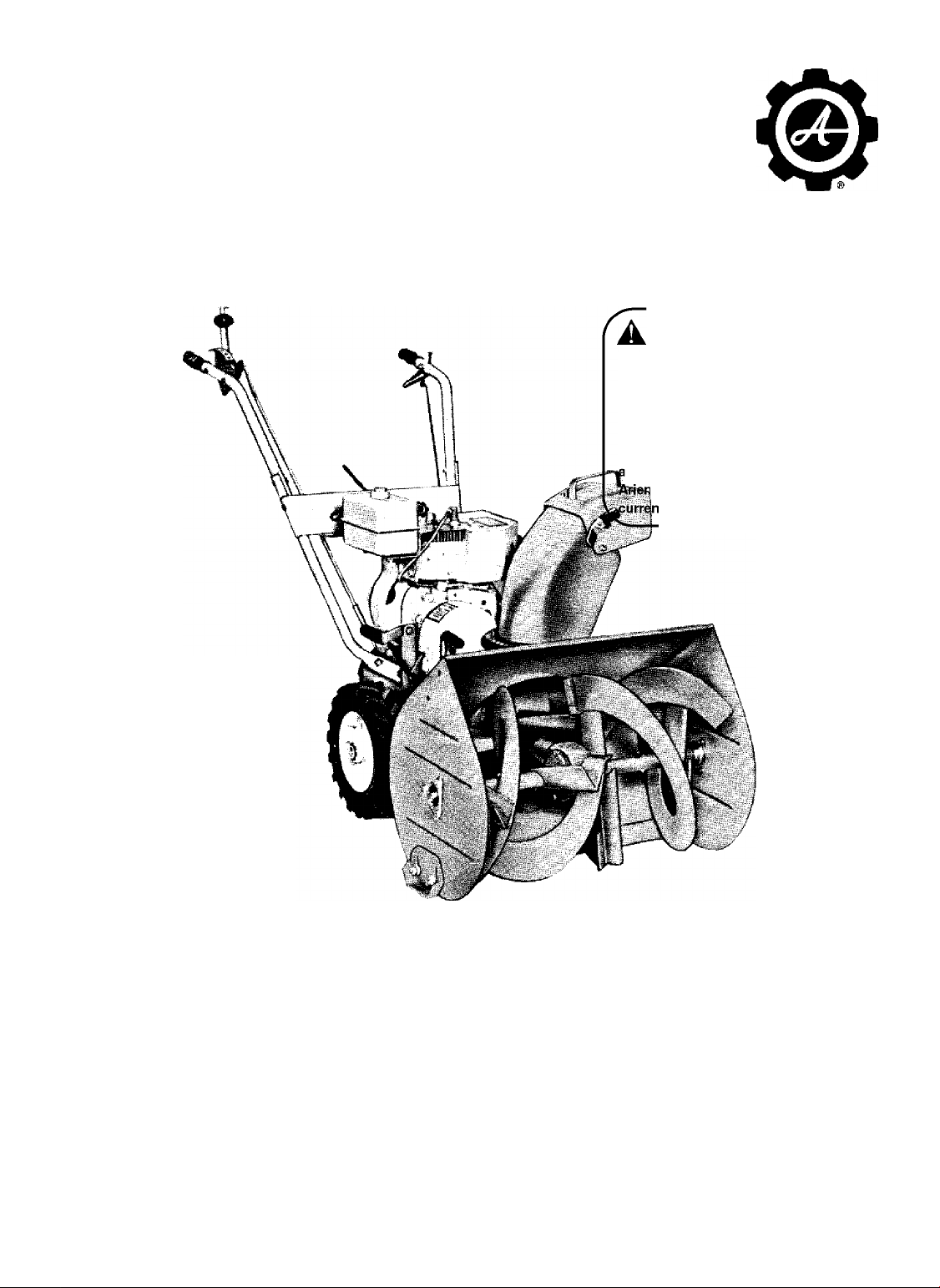
SnO-tHrO
4 H. P. MODEL
Serial Number
10M4-04501
and up
SAFETY MESSAGE
The product for which you have requested
information or replacement parts is not a current
product. The replacement models incorporate
product designs, safety features, safety
instructions or warnings which represent the latest
“State Of The Art” developments. For your safety
nd those around you please contact your nearest
|s/Gravely Dealer for a demonstration of the
t product safety provisions and features.
N -V-
PRICE $.25
WARRANTY
Ariens Company hereby warrants to the original retail purchaser all new products of its own manufacture to be free
from defects in material and workmanship.
Engine, parts or accessories not manufactured by Ariens Company, even though incorporated into its products, are
not covered by this warranty.
The warranty period shall be one year from date of original purchase, except when the product is used for rental
purposes, in which case the warranty period shall be for 45 days from date of original purchase.
Any transportation charges incurred on any product claimed defective, which shall include the time and expense
of the distributor or dealer for pickup and/or return of the unit, shall be borne by the purchaser.
This warranty shall not apply to any failure resulting from misuse, neglect or accident. Ariens Company shall not
be responsible for damage in transit or handling by any common or contract carrier. Under no circumstances, within
or without the warranty period, will the company be liable for damages for loss of use, or damages resulting from
delay, or any consequential damages.
The company reserves the right to incorporate any changes in design into its products without obligation to make
such changes on units previously manufactured.
Page 2

SAFE SNOW REMOVAL IS NO ACCIDENT
Improper use of snow removal equipment on the
part of the operator can result in injury. To reduce
this possibility, give complete and undivided atten
tion to the job at hand.
Protect Yourself and Others by Following These
Safety Tips
1. Stop motor before cleaning discharge, removing
obstacles, making adjustments, or when leaving
operating position.
2. Never direct discharge at bystanders nor allow
anyone in front of machine — debris may be
hidden in the snow.
3. Keep children and pets a safe distance away.
4. Do not allow children to operate machine nor
allow adults to operate it without proper in
struction.
5. Adjust height to clear gravel or crushed rock
surface.
6. Exercise caution to avoid slipping or falling,
especially when operating in reverse.
7. Know the controls and how to stop quickly —
read the owner’s manual.
8. Handle gasoline with care — it is highly flam
mable.
A. Use approved gasoline container.
B. Never add gasoline to a running engine —
fill tank out of doors and wipe up spilled
gasoline.
C. Replace gasoline cap securely.
D. Open doors if engine is run in garage —
exhaust gases are dangerous.
9. Disengage all clutches and shift into neutral be
fore starting motor. Keep hands, feet, and
clothing away from power driven parts.
10. Use a grounded three wire extension cord for
all plug-in electric units.
11. Keep machine in good operating condition and
keep safety devices in place.
ASSEMBLY
1. GENERAL
When impacking, be sure to remove all loose
items from the carton.
2. HANDLE BARS
a. Place the holes in the flat section of the
lower handle bars over the studs projecting from
the frame on each side of the engine.
b. Place a lockwasher and nut on each stud but
do not tighten.
c. Remove the four bolts from the lower portion
of the upper handle bar and slide the upper handle
bar in place between the curved portions of the
lower handle bars (figure 1).
d. Replace the bolts in the top hole of the lower
handle bar and the matching hole in the upper handle
bar. Fasten with locknut.
e. Hook the bent portion of the nameplate panel
over the lower handle bar and slide it up until the
holes in the panel line up with the lower holes in the
lower handle bar. Fasten in place with bolts and
locknuts.
f. Tighten the nuts holding the lower handle bar
to the frame.
3. SHIFT CONTROL
Position the shift control (figure 1) on the In
side of the handle bars on the right hand side so that
the holes in the control line up with the holes in the
handle bar. Fasten the control to the handle bar with
two hex head cap screws and lockwashers (figure 1).
CHOKE
PRIMER
ROD
HANGER
CHUTE
CONTROL
CRANK
THROTTLE
LOCK
PIN\
CLUTCH CLUTCH
HANDLE ROD
UPPER
SHIFT
ROD
SHIFT
CONTROL
LEVER
Figure 1
Page 3

4. SHIFT ROD
a. Pull up as far as possible on the lower shift
rod which projects from the rear of the engine
momiting frame (figure 1). Screw the threaded por
tion of the upper shift rod over the lower shift rod.
b. Depress the rod in the center of the shift
knob and pull the shift control back to the REVERSE
position.
c. Thread the upper rod on the lower rod imtil
the opposite end of the rod drops easily into the hole
in the shift control. Place a washer over that por
tion of the rod which projects through the shift con
trol and insert a cotter pin to hold the rod in place.
d. Tighten the locking nut on the lower shift rod.
5. TRACTOR CLUTCH ROD
a. Using a rubber band or piece of string, tie
the clutch operating handle up against the handle
bar.
b. Slide the straight end of the clutch rod
through the ball joint mounted on the clutch arm
(figure 1) and place the bent end of the rod through
the hole in the clutch operating handle (figure 1).
e. Remove the ties holding the clutch operating
handle to the handle bar and remove the wedge from
under the clutch arm.
f. Pull up on the clutch operating handle and
lock the handle in place with the locking pin. De
press the button on top of the shift lever and move
the lever to the neutral position. If the shift lever
does not move freely to the neutral position, loosen
the clamping screw in the ball joint, slide the wedge
in a little farther, and retighten the clamping screw
and remove the wedge.
6. THROTTLE CONTROL LEVER
a. Using the two self-tapping screws provided,
fasten the throttle control lever (figure 1) to the in
side of the left hand handle bar.
b. Run the control cable down the inside of the
handle bar and fasten in place with the spring clip.
7. CHUTE CONTROL ROD
a. Slide the chute control rod through the hole
in the rod hanger (figure 1) mounted on the left hand
side of the handle bar.
c. Place the small washer over the rod and
fasten in place with a cotter pin through the hole
in the rod.
d. Tighten the clamping screw in the ball joint.
LUBRICATION
1. ENGINE
See manufacturer’s instruction book for engine
lubrication instructions.
NOTE
Use MS classification 5W-20 for
operation below 40* F. Use MS
classification SAE-30 oil for op
eration above 40" F.
2. TRACTOR DRIVE
a. At the start of each season grease the gears,
hex and fork shaft, jaw coupling, and chains.
b. Two or three drops of light oil should be
placed on the shift lever release rod.
b. Slide the rod into the hole in the universal
joint.
c. Line up the hole in the rod with the hole in the
universal joint and insert the cotter pin.
with approximately 5 oz. of SAE-90 Ariens Gear Oil
every 25 hours of operation.
b. To drain and refill, remove drain plug and
allow oil to drain. Tip machine back on handle bars
(be sure clutch is locked in UP position). Pour oil
into filler hole imtil it starts to run out of drain
hole. Replace drain and filler plug.
c. Oil rake oil holes (figure 2) every 25 hours of
operation or each time a shear bolt is replaced.
OIL HOLES
SHEAR BOLT
OIL HOLES
3. SNO-THRO UNIT
a. Drain and refill the snow rotor gear case
ADJUSTMENT
BOLTS
SCRAPER
BLADE
Figure 2
OIL FILL
Page 4

OPERATING INSTRUCTIONS
1. ENGINE
Complete instructions for the operation, lubri
cation, and proper care of the engine will be found
on the instruction plate attached to the engine fan
housing and in the maniifacturer’s instruction book
packed with the engine. Do not attempt to start the
engine before following the manufacturer's recom
mendations for servicing the engine.
2. TRACTOR CLUTCH
a. The clutch operating handle mounted on the
left handle bar serves to disengage the clutch so
that the shift control lever may be moved to any one
of the four forward speeds or reverse position.
b. When the clutch operating handle is squeezed
together, the shift control lever may be moved to the
desired position. Releasing the handle will cause
the machine to move in the direction and at the speed
selected. Once the tractor is is motion, it is pos
sible, without using the clutch, to shift to a higher
or lower speed range. However, the clutch must be
used when moving the shift control lever into neu
tral or reverse.
c. A locking device is provided on the clutch
operating handle to hold the handle in the non
operating position. The lock is released by a light
squeeze on the handle.
3. SHIFT CONTROL LEVER
a. The shift control lever mounted on the right
handle bar governs the speed and direction of the
tractor.
b. To move the shift control lever to a selected
position, squeeze the tractor clutch operating handle
together, depress the button on the center of the shift
control lever knob and move the lever.
4. ENGINE CLUTCH
a. The engine clutch is controlled by a lever
mounted on the right hand side of the unit (figure 3)
just forward of the engine.
^ -w—*
SNO-THRO
CLUTCH
b. When the clutch control lever is pulled up,
the idler pulley bears against the drive belt causing
the engine to drive the tractor transmission.
c. When the clutch control lever is pushed down,
the idler pulley moves away from the drive belt,
loosening the belt and the transmission stops.
5. SNO-THRO CLUTCH
a. The Sno-Thro clutch is controlled by a lever
at the rear of the Sno-Thro blower housing (figure 3).
b. To start the Sno-Thro auger and blower, start
the engine, place the Sno-Thro clutch in the IN posi
tion (clockwise) and engage the engine clutch on the
tractor.
c. To stop the Sno-Thro auger and blower, dis
engage the engine clutch on the tractor and place the
Sno-Thro clutch in the OUT position (counterclock
wise).
d. The tractor may be used to move the unit with
the Sno-Thro auger and blower stopped by engaging
the tractor clutch while leaving the Sno-Thro clutch
in the OUT position.
6. THROTTLE CONTROL
The throttle control lever controls the speed of
the engine and therefore, in conjunction with the shift
control lever, the speed of the machine. Moving the
lever toward "F" increases engine speed and moving
it toward "S" decreases speed. Moving the lever to
the STOP position will stop the engine. ALWAYS
MOVE THE THROTTLE LEVER TO "PARK" AFTER
ENGINE HAS STOPPED.
7. CHOKE
A manual choke is provided which is operated by
a lever projecting from the carburetor cover on the
left hand side of the engine. The lever can be placed
in any one of four detent positions. Moving the lever
toward the rear of the machine places it in the FULL
CHOKE position. As it is moved forward, it will
pass through the 3/4 CHOKE and 1/2 CHOKE posi
tions to the NO CHOKE position fully forward.
8. RUNNERS
o 0"-
'<&DRAIN
ENGINE
CLUTCH
Figure 3
LATCH
a. An adjustable runner is
provided on each end of the
blower housing (figure 4).
Raising or lowering these run
ners controls the distance the
scraper blade is held above
the surface being plowed. Ad
justment is accomplished by
loosening the two nuts on each
of the rimners to the desired
position and retightening the
nuts.
LOCKNUTS
RUNNERS
Figure 4
\
Page 5

b. In wet snow which packs easily, it may be
necessary to remove the runners or turn them up
side down so the scraper blade will scrape clean.
9. ENGINE STARTING INSTRUCTIONS
a. Fill engine fuel tank with "regular" grade
gasoline.
b. Place engine clutch lever in down position and
shift control lever in NEUTRAL.
c. Place choke lever in FULL CHOKE position.
d. At temperatures below 10° F., depress pri
mer button and pull recoil starter slowly past com
pression one time. Release primer button.
■CAUTION
Do not use primer when temperature
is above 10* F.
choke lever to l/2 CHOKE position before pullii^
recoil starter a second time.
g. If engine does not start by the fifth pull
starter twice. Repeat starting procedure. DO NOT
REPRIME ENGINE BEFORE TRYING AT LEAST
FIVE PULLS ON STARTER.
10. SCRAPER BLADE
An adjustable scraper blade (figure 2) is pro
vided along the bottom edge of the blower housing.
During operation, this blade runs along the surface
being plowed directing the snow into the rotor and
insuring a clean plowed surface. After considerable
usage, this blade may wear and should be adjusted.
The blade is adjusted by loosening the five nuts
holding it to the housing, sliding it down to the new
position and retightening the nuts. The blade is also
designed so that it may be reversed if one side be
comes worn beyond further adjustment.
11. CHUTE
e. Pull recoil starter handle quickly. When en
gine starts, move choke control lever to 3/4 CHOKE
position (first notch). After 20-seconds, move choke
control lever to 1/2 CHOKE position (second notch).
After an additional 15-seconds, move choke control
lever to NO CHOKE position.
f. If engine does not start on first pull, move
The chute is designed so that it can be rotated
through an angle of 240 degrees by means of the
chute control crank mounted on the handle bar. By
turning the handle of the control rod, the blown snow
can be directed either to the right or left or straight
ahead. An adjustable deflector on the chute can be
moved up or down to control the height and distance
the snow will be blown.
Page 6

OPERATING TIPS
1. PRE-OPERATION PRECAUTIONS 3. DEPTH ADJUSTMENT
a. Before the first snowfall, be sure the area
on which the Sno-Thro is to be operated is free of
sticks, stones, toys, or other obstructions which
might be picked up by the machine during operation.
WARNING
Do not allow children to run through
the snow being discharged from the
machine. Small objects picked up
by the machine may be thrown out
of the chute with considerable force
and can cause serious injury.
b. Always allow the engine to warm up to opera
ting temperature before operating the machine in
snow.
c. Operate the machine in a cleared area be
fore operating in snow for the first time. Become
familiar with all controls before attempting to plow.
2. CHUTE ADJUSTMENT
a. The distance the Ariens Sno-Thro will throw
the snow will depend on the type of snow being
plowed. In general, the position of the deflector
will determine the distance the snow will be thrown.
Tipping the deflector down will decrease the throw
and tipping the deflector up will increase the throw.
b. The distance the snow is blown can also be
controlled to some extent by the engine speed.
Slowing down the engine by means of the throttle
control will decrease the throw and increasing speed
will increase the throw. By a combination of engine
speed and deflector adjustment, the snow can be
blown a distance suitable for nearly every situation.
NOTE
When operating the Sno-Thro in wet
snow, occasionally a sufficient
amount of snow may stick inside
the chute causit^ partial clogging.
To prevent this, it is suggested
that the inside of the chute be
coated with a light layer of "paste"
or "spray" wax. It is recommended
that the inside of the chute be waxed
two or three times each season.
How clean the Sno-Thro will plow is determined
by the adjustment of the runners. See paragraph 7
of Operating Instructions. When plowing on concrete
or other hard surfaces, these runners should be ad
justed so that they are approximately 1/8-inch below
the scraper blade. When plowing gravel driveways
or other gravel areas, adjust the runners so that
they are 1-1/4-inch below tiie scaper blade.
4. PLOWING
a. When plowing reasonable depths of ordinary
snow, it is only necessary to guide the machine along
the path to be plowed and to adjust the chute to blow
the snow with the wind. When making the second
pass on a sidewalk or driveway, allow the machine to
overlap the previous path slightly to insure complete
removal of snow.
b. When plowing through a very heavy drift, such
as one formed by the passing of the street plow, it
may be necessary to "inch" into the drift when making
the first pass. To do so, allow the machine to enter
the drift and then declutch. Allow the machine to
blow away the accumulation of snow and then move
the machine forward deeper into the drift by re
leasing the clutch handle. Again declutch and allow
the machine to clear away the snow. Continue this
process imtil a complete path has been cleared
through the drift. On the second pass through the
drift, allow the path of the machine to overlap the
first path.
5. SHEAR BOLT REPLACEMENT
Occasionally a small object may enter the rotor
and become jammed in the blades. When this occurs
the shear bolts, located on the shaft on which the
rotor is mounted, will break and allow the rotor to
turn freely on the shaft. Before plowing can be con
tinued, this shear bolt must be replaced. See figure
2. USE ONLY ARIENS SHEAR BOLTS. USE OF
OTHER TYPES OF BOLTS MAY RESULT IN SEVERE
DAMAGE TO MACHINE.
WARNING
If it becomes necessary to replace
the shear bolts or necessary to
remove any obstruction from either
the rotor, blower, or chute, STOP
THE ENGINE.
NOTE
Each time a shear bolt is replaced, the rakes must be oiled
and turned on the shaft by hand several times to insure
that they will not bind.
Page 7

y
i~~~9X7
Part
No.
1008 Clutch Fork
3017
3034
10107
10108 Gasket
10142
10154
10164
Scraper Blade
10165
Runner
10176
Sliding Jaw
10177
Helicctti Pinion
10178 Fan
10179
Blower Housing
10180 Gear Case
10181
10182
10183
Helicon Gear
10184 Bearing Support
10185 Adjustment Plug
Description
Bearing Flange
Roller
Bearing Spacer
Bearing Flange
Control Sprocket
Flange
Front Gear Shaft
No.
Req'd.
1
1
1
1
1 10190
1
1
1
2
1
1
1
1
1
1
1
1
2
1
Part
No.
10186 Fork Shaft
10187
10188 Spring
10189 R. H. Rake
10191
10192 Discharge Chute
10193 Wing Nut 1/8x1
10195
10197 Grip
10198 Cap
10199 Fastener
10229
10260
10269 Chute Clamp
10281
10284 Chute Control Crank
10290
1X44 Bearing Cup
1X45
Description
Fork Cam
L. H. Rake
Deflector
Shear Bolt
Wave Washer
Wave Washer
Chute Control Support
Universal Joint 1
Bearing Cone
No.
Req'd.
2
1
1
1
1 or 2
1
3
1
1
2
2 23X42 Locknut 5/16-18
Part
No.
1
1X63
1
1
1
1
1
1
1
Ball Bearing
2X35
Bushing
4X55 Seal
4X57
Seal
5X32
Snap Ring
9X7
Roll Pin 1/4 X 1-1/4 3
9X9
Roll Pin 1/8x1
9X16
Roll Pin 3/16 X 1 2
9X17
Roll Pin 5/16 X 1-1/4 1
9X22
Roll Pin 5/16 X 1-3/8 1
11X13
Pipe Plug 3/8 Sq. Hd.
12X23
12X24 2
14X14
Set Screw 1/4-20 x 1/4
19X9
Carriage Bolt 5/16-18 x 1/2 5
19X10 Carriage Bolt 3/8-16 x 3/4
20X4
20X6
21X2
Washer 5/16
Description
No.
Req'd.
1
2
2
1
1
1
2
2
1
5
2
2
5
Part
No.
21X46 Washer 1.505 pD x 1.005 ID x 1/16
21X47 Washer 1.441 ÒD x .511 ID x 1/8 2
21X48 Washer 1.375 OD x .755 ID x 1/16
23X39 Locknut 3/8-16
Locknut 1/4-20
23X40
23X42
Locknut 5/16-18 7
Nut #10-24
23X51
23X56 Nut 1/4-20
25X4 Cotter Pin 1/8x1
Cotter Pin 1/8 X 1-1/4
25X14
31X9 Flange Whizlock Screw 5/16-18 x 1/2
Flange Whizlock Screw 3/8-16 x 1/2
31X10
Ribbed Neck Bolt 1/4-20 x 5/8
31X11
31X12 Flange Whizlock Screw
36X4 Grip 1/2 ID
SLICER BAR KIT
SUcer Bar
10242
19X9 Carriage Bolt 5/16-18 x 1/2
Description ^No.^
4
6
3
6
6
2
2
6
2
2
1
1
1
5
1
1
Page 8

PARTS LIST FOR 4 HP TRACTOR
Part
No.
1027
2033
Spring
Handle Bar Panel
2038 Clutch Handle
2044
2045
2402
3003
3031
3085
Clutch Lock Spring
Clutch Lock Pin
Idler
Friction Wheel
Bearing Flange
Bearing Flange 2
3086 Ball Joint
5006 Key 3/16 Sq. x 1"
6071
R-1271
Spacer
Spacer Bushing
Description No.
Req'd.
Part
No.
2
10230
1 10231 Shift Quadrant
1 10232 Shift Handle 1
1 10233
1
10235
1
10237
1
10239
2
10240
10241 Upper Handle Bar
1 10247
1
10248
2 10266
1 10267
10147 Bottom Cover 1 10272
10156
R. H. Lower Handle Bar 1
10157 L. H. Lower Handle Bar 1
10158
Outer Belt Guard 1
10159 Inner Belt Guard 1
10160
R. H. Belt Finger 1
10161 L. H. Belt Finger
10194 Clutch Lever
10196
10202
10204
10205
10206
10207
10208
10209
10211
10212
10213
10214
10215
10217
10220
10222
10226
10227
10228
Handle Bar Washer
Idler Arm
Spindle
Drive Plate
Jaw Coupling
Pinion & Sprocket
Pinion Stub Shaft
Support Bracket
Spur Gear
Bracket Pin
Sliding Fork
Fork Shalt
Lever Bracket
Transfer Lever
Clutch Bracket
Disc Bracket
Neutral Catch
Throwout Lever
Lower Shift Bod
10275
10276
10277 Friction Disc Hub 1
10279 Axle Shaft
10285
10288
1
10289 Eye Bolt Rod Hanger 1 23X43 Locknut 5/16-24
1
10293
2
10294 Engine Sheave
1
12023
1
1X63 Ball Bearing 2
1
1X74
1
1X78 BaU Bearing
1
2X26
1
2X34 Bushing
1
5X37 Retaining Ring
1
5X43
1
8X8 Clevis Pin
1
9X16 Roll Pin 3/16 X 1 2
1
12X22
1
12X50
1
12X53
1
12X56
1
12X69
1
1
1
Description
Clutch Rod 1
No.
Req'd.
1
Part
No.
12X72
12X73 Capscrew 5/16-18 x 1-3/4
12X74
Spring
1 14X12
Shift Rod 1 20X2
Chain
Sheave 1
20X3
1
20X4
Idler Arm Hub Spacer 1 21X2
1
Ball Joint
Shift BaU
Tractor Frame
Bearing Housing
Carburetor Cover (Not lUus.)
Hex Shaft
Sprocket 1
21X7 Washer 1/4
1
21X33 Washer
1
21X37 Washer
1
21X38 Shim Washer
1
21X42 Washer
1
21X43 Washer
1
23X15 Nut 5/16-18
23X18
23X31
1
Connecting T.lnk
Hub Cap 2
Shift Release Handle 1
23X40
1
23X41
23X42 Locknut 5/16-18
23X54 Locknut 1/2-20
1 23X56 Nut 1/4-20
Bearing Support 2
24X11
24X12 Key #91 Woodruff 1
Thrust Bearing
Bushing
Snap Ring
1
24X15
2
25X1 Cotter Pin 3/32 X 3/4
2 25X4 Cotter Pin 1/8x1 3
2
25X10
1
25X14
1
28X12
1
28X32 Throttle Control
31X9 Flange Whizlock Screw 5/16-18 x 1/2
Capscrew 5/16-18 x 3/4 3
Capscrew 1/4-20 x 1-1/2 5
Capscrew 5/16-24 x 3/4
Capscrew 1/4-20 x 1-1/4
Capscrew 5/16-18 x 1-1/4 1
31X10
31X11 Ribbed Neck Bolt 1/4-20 x 5/8 6
33X62
2
34X89 Belt
2
35X1 Self-Tapping Screw #10 x 1/2
36X5
36X6 Grip 1 X 4-1/2 or 5
Description No.
Req’d.
Capscrew 1/4-20 x 1-1/4
Capscrew 5/16-18 x 2/3/4
Set Screw 5/16-18 x 3/8
Lockwasher 1/4 Std.
Lockwasher 5/16 Std.
10
Lockwasher 3/8 Std.
Washer 5/16
15
1 or 2
Nut 3/8-16
Nut 5/16-24
Locknut 1/4-20
Locknut 3/16 10-24
Feather Key 2
Key #5 Woodruff
Hair Cotter Pin 2
Cotter Pin 1/8 X 1-1/4
Cable Clamp 1
14
Flange Whizlock Screw 3/8-16 x 1/2
Tire & Wheel Assembly
Grip 3/4 X 3-1/2 1
1
1
1
2
2
4
1
1
1
2
1
7
4
2
8
8
4
2
2
6
1
2
3
1
4
2
1
4
2
Page 9

Page 10

SERVICE
1. GENERAL
Ariens dealers will provide any service which
may be required to keep the Sno-Thro operating at
peak efficiency. The Sno-Thro is equipped with the
finest quality engine obtainable. However, should
servicing be required, it can be obtained from an
Ariens dealer or authorized engine manufacturer's
service station. Consult an Ariens dealer for details.
ACCESSORIES
1. SLICER BAR (3-10M)
The slicer bar is available as
optional equipment for Model
10M4. The SLICER BAR is de
signed to cut through deep snow
and dislodge crusted or drifted
snow. The bar can be installed on
either side of the SNO-SCOOP.
Figure 5
2. ENGINE
Refer to the engine instruction book and name
plate on the engine for maintenance instructions.
If repairs or service are needed for engine, see an
Ariens dealer or nearest authorized engine service
station.
2. TIRE CHAINS (1-10M)
Tire chain kit number 1-lOM is available for
3x12 semi-pneumatic tires.
3. TIRE CHAINS (2-10M)
Tire chain kit number 2-lOM is available for
4:00x6 pneumatic tires.
4. PNEUMATIC TIRE KIT (6-10M)
Pneumatic tire kit 6-lOM is available for Model
10M4 Sno-Thro.
Page 11

aVUttAÎL
"GARD-N-YARD!’ TOOLS
ARIENS JET SERIES rotary illlers with Turbo Tines.
Choice of 3, 4 or 5 h.p. with tine reverse drive.
ARIENS EMPEROR riding mower. Available with Flex-NFloat 26" or 32" rotary; Insta-hitch attachments. Electric
or Impulse starting 6 h.p. engine.
ARIENS ROCKET rotary tiller with TURBO TINES and
frictlon-drive Tine Reverse. 20" tilling width. 6 h.p.
Lauson engine. For commercial, professional and home
gardener use.
ARIENS TRANS-A-MATIC for heavy duty commercial till
ing. Choice 9.0 h.p. or 16.5 h.p. Wisconsin engine; 20"
or 28" tilling widths. Non-slip differential.
Form No. ST4-65R
ARIENS SNO-THRO Self propelled, 2 stage, heavy duty,
4 or 6 h.p. rotary snow thrower. 180° swiveling
SNO-CHUTE with hand crank directional control.
ARIENS COMPANY
109 CALUMET STREET
BRILLION, WISCONSIN
ARIENS TILLIVATOR. Tractor mounted, custom-built tillers
for large scale vegetable growers.
Modern, efficient plant of the Arlens Company where
GARD-N-YARD tools are manufactured.
Printed in U. S. of A.
 Loading...