

Page 1
CT^iens
Series
A SAFETY MESSAGE A
The product for which you have requested
information or repiacement parts is not a
current product. The repiacement models
incorporate product designs, safety features,
safety instructions or warnings which repre
sent the latest "State Of The Art” develop
ments. For your safety and those around you
please contact your nearest Ariens/Gravely
Dealer for a demonstration of the current
product safety provisions and features.
Owner's
Sno-Thro
Manual
Page 2

A Message to Ariens Customers...
Welcome to the world of Ariens equipment. We are
pleased that you have purchased the best equipment
available. The care you give your Ariens equipment
will determine the satisfaction and service life you will
obtain from it. Use this manual, and the engine
manual supplied, as your guide. By observing the
instructions and suggestions in these manuals, your
Ariens equipment will serve you well for many years.
Your Ariens dealer will be happy to supply any
service or advice which may be required to keep your
Ariens equipment operating at peak efficiency. He
stocks genuine Ariens parts and lubricants
manufactured with the same precision and skill as the
original equipment. His factory trained staff is kept
well informed on the best methods of servicing Ariens
equipment and is ready and able to serve you. If
engine repair or service is required, they can be
Safety Alert Symbol And Notations
obtained from an Ariens dealer or from an authorized
engine manufacturer's service center. If service is
required, be prepared to supply the sen/ice person
with the Model and Serial Number of the equipment
and the engine, as well as a full description of the
problem encountered.
NOTE: The descriptions and specifications
contained in this manual were in effect at the time the
manual was approved for printing. Ariens Company
reserves the right to discontinue models without
notice and without incurring obligation. The
equipment described within this manual may not be
identified as either standard or optional and the
various illustrations may not all be applicable to your
particular unit. If you have questions, always check
with your Ariens dealer.
The following safety notations are used throughout
this manual to call attention to special information or
operating procedures. Understand the message in
each notation and be alert to unsafe conditions and
the possibility of personal injury.
NOTE: A NOTE points out general reference
inforrriation regarding proper operation and
maintenance practices.
IMPORTANT: An IMPORTANT statement indicates
specific procedures or information that is required to
prevent damage to the machine or its attachments.
This safety alert symbol is used to
attract your attention! PERSONAL
A
SAFETY IS INVOLVED! When you see
this symbol - BECOME ALERT - HEED
ITS MESSAGE.
A
A
A
CAUTION: A CAUTION identifies safe
operating practices or indicates unsafe
conditions that could result in personal
injury.
________________________________
WARNING: A WARNING describes a
condition where failure to follow the
instructions couid result in severe
personal injury.
DANGER: A DANGER designates a
condition where failure to follow
instructions or heed warning will most
likely result in serious personal injury
or death.
Page 3

Contents
Model
IT Accessory..............................................................12
Adjustments........................................................10
Controls and Features........................................ 5
Decals....................................................................3
Lubrication and Maintenance
Operation
Preparation for Operation
Safety Alert Symbol and Notations
Safety Precautions
Specifications.....................................................12
Storage...............................................................
Warranty
Specific Model and Serial Numbers are on a label
located on the frame of your Rotary Brush and on a
label located on the product registration.form.
Record those numbers below and transfer the label
from the product registration to place indicated below.
Use these numbers whenever parts or service is
required.
.............................................................
..............................................
.............................................................
......
.......................
...................................
.....................
12
14
r
TRANSFER
I
Model Number
Serial Number.
I
I
.1
I
MODEL SERIAL
LABEL FROM
PRODUCT
REGISTRATION
6
Model 937004 Ariens Recoil Start
3 H.P. 21" Two Stage Sno-Thro
Serial No. 000101 and up.
9
4
i
1
NOTE: All references to “Left”, “Righf, “Front” and
“Rear'’ are given from operator’s position.
Safety Precautions
Training
Read and understand this Owner's Manual and
engine instructions before operating unit. Be
thoroughly familiar with controls and proper use of
equipment. Know how to stop unit and disengage
control quickly in an emergency.
Use only accessories designed for your unit. See
your Ariens Dealer for a complete list of accessories.
Understand and follow each Danger, Warning,
Caution and instruction decal installed on equipment.
NEVER allow children to operate equipment. DO
NOT allow adults to operate unit without proper
instructions.
Keep the area of operation clear of all persons,
particularly children and pets.
©Ariens 1994
Safe operation of this equipment requires your
complete and unimpaired attention at all times. DO
NOT operate unit after or during the consumption of
medication, drugs or alcohol.
Preparation
Before first snowfall of the season clearly mark
location of all obstacles (such as driveway markers,
water or gas shut off and etc.) so that they can be
avoided when throwing snow.
Thoroughly inspect and clear work area of objects
which might be picked up and thrown. Remove all
doormats, sleds, boards, wires, bones and other
foreign objects.
Wear adequate winter outer garments, gloves and
rubber footwear which will improve footing on slippery
surfaces.
Part Number 037097A
Printed in U.S.A.7/94
Page 4

Safety Precautions (Continued)
Wear eye protection such as safety goggles to
protect eyes from objects that may be thrown from
machine.
DO NOT wear loose clothing or scarves that may get
caught in rotating parts of unit.
Gasoline is highly flammable and its vapors are
explosive. Handle with care. Use an approved
(RED) fuel container.
NEVER allow smoking materials, sparks or flame
(match, pilot light, etc.) near equipment or fuel
container.
Check fuel supply before starting engine. Fill fuel
tank outdoors with extreme care; DO NOT fill fuel
tank indoors, when engine is running or while engine
is still hot from operation. Replace fuel cap securely
and wipe spilled fuel before starting engine.
DO NOT use unit on loose gravel that may be picked
up and thrown out discharge chute causing damage
or injury.
NEVER attempt to make any adjustments to unit
while engine is running (except where specifically
recommended).
Operation
DO NOT put hands or feet near rotating parts,
clear of discharge opening at all times.
Check function of all controls before starting engine.
Keep all safety devices and guards in position and
operating properly or personal injury may result.
Open doors if engine is run in garage, exhaust fumes
are dangerous. DO NOT run engine in an enclosed
area.
Operate equipment only when there is good visibility
and tight.
Always be sure of your footing (walk never run).
Exercise caution to avoid slipping or falling.
Disengage power to auger/impeller when unit is
being transported or is not in use.
Keep
DO NOT overload machine capacity by attempting to
clear snow at too fast a rate.
NEVER direct discharge of material toward
bystanders nor allow anyone in front of equipment
while unit is in operation. Be familiar with area of
operation.
Stay alert for holes, rocks, roots and hidden hazards
in area of operation.
Exercise extreme caution when operating on or
crossing gravel drives, walks or roads. Stay alert for
hazards and traffic. DO NOT operate unit near glass
enclosures, automobiles, window wells, drop-offs,
etc., without proper adjustment of discharge direction
and angle.
DO NOT clear snow across face of slopes. Exercise
extreme caution when changing direction on slopes.
DO NOT attempt to clear steep slopes.
Stop engine, remove key and wait for moving parts to
stop before leaving operator's position for any reason
such as; unclogging auger/impeller housing or
discharge chute, when making any repairs,
adjustments, inspections or cleaning unit.
DO NOT touch equipment parts which might be hot
from operation. Before attempting to maintain, adjust
or service allow such parts to cool.
If equipment vibrates abnormally, disengage
attachment, stop engine at once, and remove key.
Abnormal vibration is a warning of trouble. Repair
any damage before restarting unit.
After striking a foreign object, stop engine, remove
key and wait for moving parts to stop before leaving
operator's position. Thoroughly inspect unit for any
damage and repair damage before restarting and
operating unit.
Run unit a few minutes after throwing snow to
prevent freeze up of auger/impeller in housing.
Take all possible precautions when leaving unit
unattended, such as disengaging power to
attachment, stopping engine and removing key to
prevent unauthorized use.
Page 5

Safety Precautions (Continued)
Maintenance and Storage
DO NOT change engine governor setting or
overspeed engine.
Keep aii nuts, bolts and screws tight and be sure
equipment is in safe working condition. Check all
hardware at regular intervals.
Refer to Owner's Manual for important instructions if
Sno-Thro is to be stored for extended periods.
Never store equipment with fuel in tank inside a
building where fumes mdy resbh an open flame or
spark. Allow engine ff.. eool before storing in any
enclosure.
Maintain or replace safety and instruction decals as
necessary.
Page 6
SAFETY INSTRUCTIONS
TO AVOID POSSIBLE INJURY READ
OWNERS MANUEL AND UNDERSTAND
PURPOSE OF ALL SAFETY ALERTS
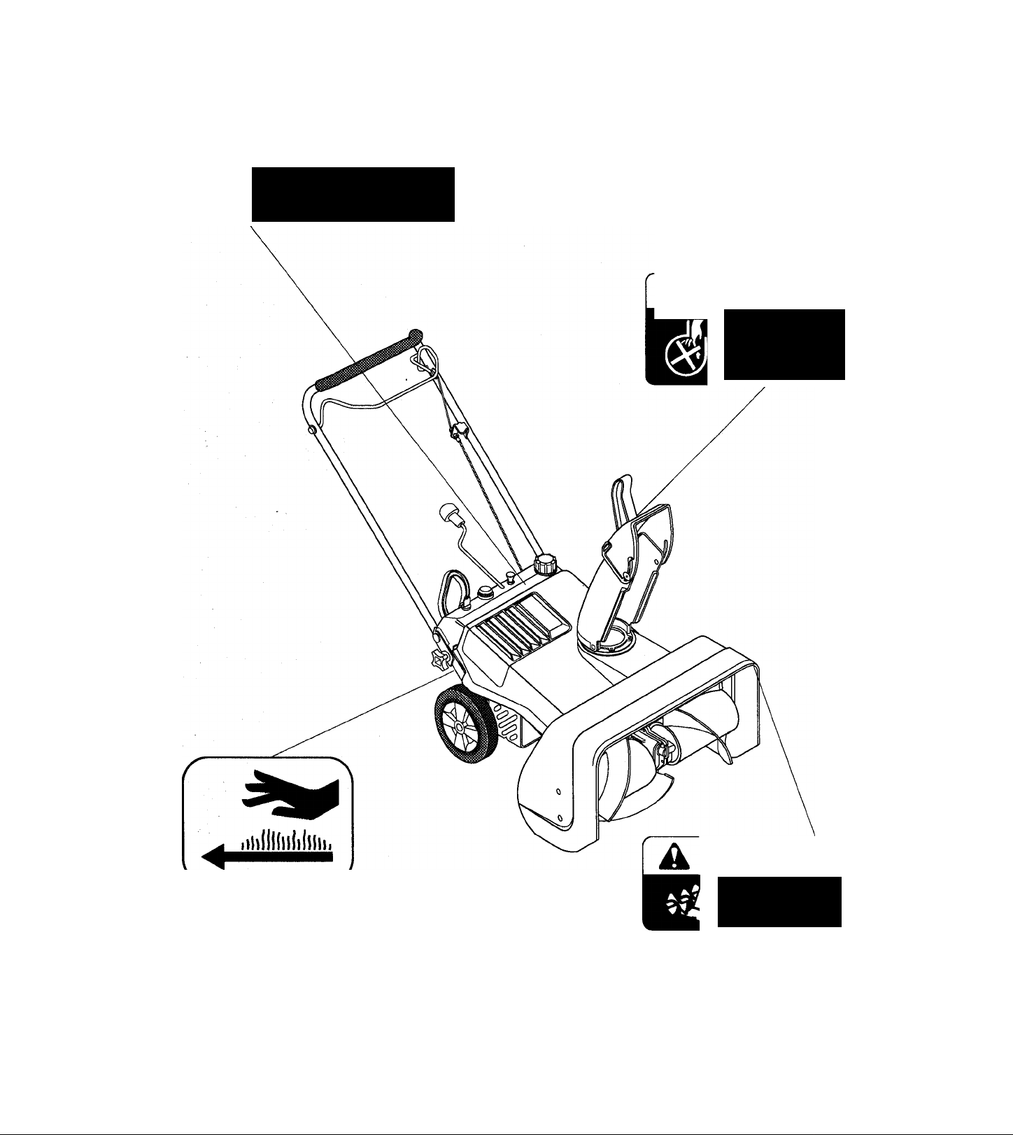
Safety Decals
A DANGER
ROTATING
PARTS
Stop engine &
remove ignition
key before clearing
Figure 1: Decal Locations
4
DANGER]
Keep clear of
auger while
engine is running.
Page 7

Dealer Preparation For Operation
Customer Note: Your Ariens Dealer is expected to
complete these preparation steps and review
important information, including this manual, with you
before or upon delivery of machine or attachment.
The preparation information is included here so that
you and your dealer may review it together.
WARNING: Failure to follow all
instructions could result in personal
A
IMPORTANT: 2 cycle engines require that oil be
mixed with fuel. Refer to Fuel in Operation Section of
this manual for recommended mixture.
Discharge Chute
Remove rear cap screws and nuts from rear of
discharge chute, tip discharge chute up and install
hardware just removed. Tighten hardware at rear of
discharge chute first then at sides.
injury and/or damage to sno-thro.
Remove wire from spark plug before
attempting any adjustment or assembly
procedure.
Engine Fuel
WARNING: Gasoline is highly
A
A
Fill fuel tank with unleaded gasoline and oil mixture.
Tank capacity is 1 quart.
Registration
Complete Sno-Thro Prewarranty Registration Form
and mail original copy to Ariens Company.
Warranty is registered under model and serial
number found on a label on unit.
Delivery
flammable and its vapors are explosive.
Handle with care. Use an approved
(RED) gasoline container.
CAUTION: Check function of all
controls before starting engine. All
safety devices and guards must be in
position and operating properly or
personal injury may result.
Discharge Chute Crank
With discharge chute facing forward, remove engine
cover. With knob down, place Discharge Chute
Crank rod through hole in dash panel and into pinion
on discharge chute. Secure with hair pin. Replace
enginecover.
Handlebar
Attach upper handlebar to lower using washers,
washers, lock bars and knobs.
Refer to Adjustments Section and check Attachment
Brake and Clutch for proper function.
Auger Gear Case
Check grease level in auger gear case (refer to
Lubrication and Maintenance Section of this manual).
lock
Using the Owner's Manual instruct the customer on
controls and operation of unit. Emphasize safety and
discuss the Safety Precautions.
Explain recommended lubrication and maintenance
of unit.
Advise customer on adjustments.
Explain Ariens Company, Limited Warranty Policy, fill
out Original Purchaser Registration Card, Parts and
Repair Manuals order Form and return to Ariens
Company. Place Model and Serial Number on page
(1) of this manual.
Give customer his Owner's Manual and advise him to
thoroughly read and understand Sno-Thro Owner's
Manuals.
Page 8

Controls and Features
O
1. Chute Bail
2. Fuel Tank and Cap 10.
3. Chute Deflector
Discharge Chute
4.
Auger/Impeller Housing 13. Primer Bulb
5.
Auger 14. Chute Crank
6.
Scraper Blade 15. Choke
7.
Impeller
8.
Figure 2: Control and Feature Locations
6
9. Handlebar Knob
Lock Bar
11. Recoil Starter
12.
Key Switch
Page 9

A
Operation
WARNING: Wear adequate winter outer
garments and footwear which will
improve footing on slippery surfaces.
Wear eye protection such as safety
goggles to protect eyes from objects
that may be thrown from machine. DO
NOT wear loose clothing or scarves
that may get caught in rotating parts of
unit.
Ariens 2 cycle oil has been formulated to insure
maximum engine performance and increased engine
life. Premix Ariens oil (1-50 ratio) per instructions on
container. If Ariens oil is not available, select a
quality 2 cycle oil BIATC (Boating Industry
Association Two Cycle) approved oil and use
unleaded gasoline.
If oil manufacturer does not recommend mixing ratio,
mix at the 1 to 50 ratio.
CAUTION: Make sure all hardware is
tight, all safety devices in place and all
A
IMPORTANT: Check impeller to be sure it is not
frozen. With key in its off position move clutch bail to
engaged position, and pull recoil starter. If impeller is
frozen, (can not pull recoil starter) move Sno-Thro to
a heated area and thaw to prevent possible damage
to unit.
NOTE: This product is equipped with an internal
combustion engine. DO NOT use unit on or near any
unimproved, forest-covered or brush-covered land
unless exhaust system is equipped with a spark
arrester meeting applicable local, state or federal
laws. A spark arrester, if it is used, must be
maintained in effective working order by operator.
Fuel
IMPORTANT: Failure to mix oil with gasoline will
result in seizure and severe damage to engine. DO
NOT use gasohol or gasoline containing alcohol
because alcohol will attack and cause internal parts
to deteriorate.
NOTE: To prevent foreign particles from entering
tank while filling: wipe snow, dust, dirt and debris
from around cap before removing.
A
adjustments correct.
WARNING: Gasoline is highly
flammable and must be handled with
care. Allow engine to cool several
minutes before removing fuel tank cap.
Never fill tank when engine is running
or hot from operation. DO NOT allow
open flame, matches, or smoking in
area. DO NOT overfill. Wipe up any
spills and allow vapors to dissipate.
Use approved (RED) gasoline
container.
NOTE: After fuel mixture has been left standing for a
prolonged time it will begin to separate, therefore
thoroughly shake mixture before using.
Chute Deflector
Position Deflector at desired height. DO NOT throw
snow any higher than necessary.
NOTE: Tighten locking hardware on chute deflector
if it does not stay in set position.
Discharge Chute Crank
DANGER: DO NOT put hands or feet
near or under rotating parts. Keep clear
A
A
IMPORTANT: DO NOT operate Sno-Thro near glass
enclosures, automobiles, window wells, drop off etc.,
without proper adjustment of discharge direction and
angle.
Direct snow away from area to be cleared and with
direction of wind whenever possible. Crank rotates
chute 210 degrees.
Snow is best removed as soon as possible after a
snow fall.
of discharge opening at all times.
WARNING: NEVER direct discharge of
material toward bystanders nor allow
anyone in front of equipment while unit
is in operation. Be familiar with area of
operation.
Page 10

Operation (Continued)
starting
CAUTION: DO NOT attempt to start
A
NOTE: Try out each control without running engine
to see how they work and what they do.
your engine at this time. Thoroughly
read this entire Owner's Manual and
engine manufacturers operating
instructions first.
Figure 3: Engine Ignition
Primer Bulb
Push primer bulb two or three times when engine is
cold. When temperatures are below -15 degrees
Fahrenheit, additional priming may be needed.
Recoil Starter
WARNING: To prevent discharge
A
Stand to right of unit. Grasp starter handle and pull
rope out slowly until it pulls harder, this is
compression stroke, let rope rewind slowly.
Then pull rope with a rapid continuous full arm stroke.
Let rope rewind slowly.
IMPORTANT: DO NOT let starter handle snap
against bracket.
Repeat above instructions until engine starts. (Refer
to engine manufacturers instructions).
toward operators' starting position,
always turn discharge chute straight
ahead for starting unit.
Engine Ignition
WARNING: If equipment vibrates
abnormally disengage attachment, stop
A
A
To start engine, place Key in Switch and turn it
clockwise to "RUN" position.
Choke
Pull choke control to “Choke" position. When engine
has started, open choke gradually.
NOTE: A warm engine requires less choking than a
cold engine.
engine at once, and remove key.
Abnormal vibration is a warning of
trouble. Repair any damage before
restarting unit.
CAUTION: Turn Key "OFF" and remove
it before attempting any maintenance,
adjustment or leaving unit unattended.
Electric Starter (Optional Accessory)
Connect power cord to switch box first then plug
other end into 120 volt AC receptacle.
Push Starter Button to crank engine.
IMPORTANT: This electric starter is not equipped
with a thermal cut-out switch. DO NOT crank engine
for more than a total of 20 seconds without allowing
electric starter to cool down for 10 minutes. Failure
to do this can severely damage electric starter.
When engine starts, release starter button and
disconnect power cord from receptacle first, then
from switch box.
CAUTION: DO NOT overload machine
A
capacity by attempting to clear snow at
too fast a rate.
Page 11

CAUTION: Operate equipment only with
A
A
Clutch Bail
good visibility and light.
CAUTION: Stay alert for holes, rocks,
roots and hidden hazards in area of
operation. Exercise extreme caution
when operating on or crossing gravel
drives, walks or roads. Slay alert for
hidden hazards or traffic.
Operation (Continued)
During snow removal, auger propels unit forward
while collecting snow. The forward speed will vary
according to snow depth and moisture content, and
scraper blade adjustment.
Efficient unit operation depends on proper scraper
blade adjustment. Refer to Scraper Blade in
Adjustment Section.
NOTE: When transporting, unit should be shut off.
To transport unit to or from an area to be cleared,
press down on handlebar enough to raise front of
Sno-Thro slightly off surface and push or pull unit.
%
CAUTION: Stop engine and remove
wire from spark plug after striking a
A
Snow is best removed as soon as possible after a
snow fall. Squeezing Clutch Bail against handlebar
engages auger and impeller so machine will move
forward and throw snow. Releasing Bail disengages
auger and impeller and brake stops rotation.
IMPORTANT: Check impeller to be sure it is not
frozen. If belt squeals when Clutch Bail is engaged,
impeller is frozen, release Clutch Bail and move unit
to a heated area to thaw.
A
foreign object. Thoroughly inspect snothro for any damage and repair damage
before restarting and operating unit.
CAUTION: Check clutch disengagement
before each use. If auger/impeller does
not stop quickly, when clutch bail is
released, adjust or repair per
Adjustment Section of this manual
before operating unit.
To clear an area, run Sno-Thro in an overlapping
series of paths. For large areas start in middle and
throw snow to each side so you do not have to move
it more than once.
Stopping
WARNING: Take all possible
precautions when leaving unit
A
IMPORTANT: Run attachment a few minutes after
throwing snow to prevent freeze-up of auger/impeller.
Release Clutch Bail and turn engine Ignition Key to
"OFF".
unattended. Such as disengaging
power to attachment, stopping engine
and removing key to prevent
unauthorized use.
Page 12

Lubrication and Maintenance
Ariens Dealers will provide any service which may be
required to keep your Sno-Thro operating at peak
efficiency. Should engine service be required, it can
be obtained from an Ariens dealer or an authorized
engine manufacturer's service center.
WARNING: Stop engine, remove key
and wait for moving parts to stop before
A
A
Engine Cooling
Engine is air cooled. Air must circulate freely around
engine from air intake screen, over cooling fins on
cylinder head and block, to prevent overheating.
attempting any lubrication or
maintenance procedures.
CAUTION: DO NOT touch engine or
Sno-Thro drive parts which are hot from
operation. Allow such parts to cool
before servicing unit.
Every 100 operating hours or yearly (more often if
conditions require) remove cooling shrouds and clean
cooling fins. Also clean external surfaces of engine
of dust, dirt and oil deposits which can contribute to
improper cooling.
IMPORTANT: DO NOT operate engine with cooling
shrouds removed, this will cause overheating and
engine damage.
Drive Belts
WARNING: Gasoline is highly
flammable and its vapors are explosive.
A
A
Handle with care. Never allow smoking
materials, sparks or flame (match, pilot
light, etc.) near equipment or fuel
container.
CAUTION: When unit is tipped up onto
housing, remove enough fuel so that no
spillage will occur.
1. Auger/Impeller Drive
Belt
2. Engine Drive Belt
3. Idler
4. Idler Pin
5. Extension Spring
6. Compression Spring
Washer
7.
8.
Lock Nut
9.
Pivot Bracket
Hair Pin
10.
Bracket Pin
11.
Pin Plate
12.
13. Cap Screws
10
Figure 4: Drive Belts
Page 13

Lubrication and Maintenance (Continued)
When replacing belts, replace both belts at same
time. To replace drive belts, disconnect extension
spring and relieve compression of compression
spring on pivot bracket.
Remove idler pin from idler and bracket then idler
from machine.
Remove two hair pins from bracket pin. Cap screw
from pin plate and pin and plate from unit.
Remove pivot bracket and belts from unit.
Install new belts in reverse order.
NOTE: Make sure pulleys align. If-alignment is
necessary, loosen pin plate cap screw, align belts
and tighten cap screw.
Auger Gear Case
IMPORTANT: Too much lubricant may cause
excessive leakage. Too little lubricant will cause gear
and/or bearing darhage.
Gear cases are filled to the correct level at the
factory. Unless there is evidence of leakage, no
additional lubricant should be required. Check for
evidence of leakage every 25 hours of operation.
To insure adequate oil level, (2 oz. mininum), the
following checking procedure is recommended,
especially if there is evidence of leakage. Find a flat
level surface adjacent to a vertical surface (floor next
to wall or post etc). Make a mark on the vertical
surface with marker or tape 10.0 inches up from the
flat level surface. (One inch wide masking or
wrapping tape works especially well).
Remove the gear case oil fill plug. Wipe the inside
end clean with a soft cloth and replace finger tight.
Move the front of the sno thro near the vertical
surface and slowly raise the handlebars until the
mark is seen at the top of the auger/impeller housing.
Count to 100 while holding at the position to insure
that the lubricant has had time to seek a stable level.
Return the sno thro to its level operating position and
remove the gear case oil fill plug to determine if the
end previously wiped clean has been “wetted” by the
lubricant. If so, lubricant level is adequate. Replace
the fill plug.
'A
1. Auger Gear Case
2. Gear Lube Fill
3. Ariens Special L-2 Gear Lube
Figures: Auger Gear Case
When adding lubricant, add only Ariens special gear
lube L-2 (Part Number 000080). After adding
lubricant, you may want to check to insure the level is
not too high. To do this, repeat the above procedure
with the mark on the vertical surface one inch higher.
Allow plenty of time to drain at this position with the
fill plug removed. 5 inch high blocks inserted under
the wheels of all models serve well to hold them in a
“drain-to-maximum-level” position.
11
Page 14

Adjustments
Ariens Company recommends that you have
adjustments made by your Ariens dealer. He has
tools and the know-how to properly perform
adjustments which may be required to keep your
Sno-Thro operating at peak efficiency. Should you
decide to make the following adjustments on your
Sno-Thro yourself, Ariens Company recommends
that you call your dealer for answers to any questions
that might arise.
WARNING: Gasoline is highly
flammable and Its vapors are explosive.
A
A
Scraper Blade
A
Handie with care. Never aiiow smoking
materials, sparks or flame (match, pilot
light, etc.) near equipment or fuel
container.
CAUTION: When unit is tipped up onto
housing, remove enough fuel so that no
spillage will occur.
CAUTION: DO NOT use this machine on
loose gravel. Gravel may be picked up
and thrown from discharge chute
resulting in damage to nearby property
and/or injury to bystanders.
To adjust scraper blade, tip unit back and rest unit on
handlebar. Loosen nuts on carriage bolts along
scraper support. If unit does not scrape cleanly,
move scraper blade forward. If unit does not drive
forward and scraper blade drags, move scraper blade
to the rear.
NOTE: Tighten hardware and test unit. Repeat
adjustment as required until proper operation is
obtained.
Engine Belt
CAUTION: For proper braking and
engine belt engagement, with Clutch
A
To adjust, turn nuts on upper cable end until there is
the proper spring extension and lock in position by
locking nuts against bracket.
Bail disengaged, there must be slack in
cable. There should be 3/16" to 1/4"
extension of cable spring when Clutch
Bail Is held against handlebar.
1. Scraper Blade
Figures-. Scraper Blade
Scraper Blade is adjustable to compensate for wear
and to control auger traction (auger propels unit).
Adjust scraper blade equally its full length if machine
does not scrape cleanly or if machine does not drive
forward properly.
2. Carriage Bolts
and Nuts
12
Page 15

Adjustments (Continued)
Belt Alignment
When replacing belts, replace both belts at the same
time. To align belts, loosen pin plate cap screw, align
pulleys and secure with cap screw.
Auger/Impeller Belt
For proper tension of auger/impeller belt, tip unit up
on auger/impeller housing. Check that idler pin is in
position with flat of pin toward center of unit.
Loosen lock nut far enough so that compression
spring and washer are free to rotate. Then tighten
nut until spring no longer turns freely. From this
position, tighten lock nut exactly eight (8) turns to
provide proper tension on auger/impeller belt.
WARNING: With improper use injury
may result if clutch bail is released and
A
brake DOES NOT STOP auger/impeller
within 5 seconds.
1. Lock Nut
2. Compression Spring
3. Idler Pin
Figure 8: Auger/impeller Belt Adjustment
m
13
Page 16

PRODUCTS
GUARANTEE
LEVIITED
WARRANTY
PROTECTION PLAN
• The Company will provide for the replacement of any
part found upon examination by the Company to be
defective. Such repair or replacement will be free of
charge to the purchaser (labor and parts) for two years
(24 months) from the date of purchase. Ariens
manufactured parts (but not labor) will be free of charge
for an additional thme years (36 months) thereafter
This warranty Is subject to the following exceptions and limitations:
PURCHASER RESPONSIBILITIES -
• Maintenance & minor adjustments per owners manual
• Notification of need for warranty senrice
• Transportation to/from place of warranty repair
PRODUCT REGISTRATION -
• Return of registration card required to validate
warranty
PURCHASED COMPONENTS AND NORMAL WEAR -
• TWO year labor and parts on purchased components
i.e., (tractor drive train components manufactured by
'PURCHASED!
W»R
Dana, Eaton, Foote, Sundstrand and any plastic and
electrical components, wire harnesses, bags, boots
tubes, etc.).
• Two year labor and parts on normal wear items i.e.,
(belts and rubber components, bearings, cables,
controls, clutches, tines, etc,).
BATTERY WARRANTY PRORATED -
• One to six months • free replacement
• Seven to twelve months - 50 % credit
• Thirteen to twenty-four months - 25% credit
WARRANTY - COMMERCIAL PRODUCTS -
• One year parts and labor
• Product labeled commercial / professional
• Household use - 5 year limited warranty applies
RENTAL USE - ALL PRODUCTS
• NINETY DAYS LABOR & PARTS
CONSUMER PRODUCT - PUT TO
COMMERCIAL, INDUSTRIAL, INSTITUTIONAL USE
• NINETY DAYS LABOR & PARTS
SERVICE PARTS AND ACCESSORIES -
• NINETY DAYS LABOR & PARTS
Ariens Company hereby wanarrts to the original consumer purchaser that
products manutaetured by Ariens Company will be free from defects In material
and worionwishlp FOR A PERIOD OF FIVE (SI YEARS FROM THE DATE OF
PURCHASE EXCEPT AS NOTED BELOW.
SERVICE -
• For warranty service, contact any Ariens Distributor or
[c4lem
Ariens Company reserves the right to Incorporate any changes in design
Into its products without obligation to make such changes on products
previously manufactured.
DISCLAIMER OF FURTHER WARRANTY
There Is no other express warranty. Implied warranties. Including any
warranty of merchantability or fitness for a particular purpose, are limited
to the duration of this written warranty, and are excluded to the extent
permitted by law. There are no warranties which extend beyond the
description of the product contained herein. In no event shall the company
be liable for Indirect, special or conaequentlal damages (such as loss of
anticipated profits) In connection with the consumer's use of the product.
This warranty gives you specific legal rights, and you may also have other
rights which vary from state to state. Some states do not allow the
exiuslon of Incidental or consequential damages, or limitations on how
tong an Implied warranty lasts, so the above limitation and exclusions may
not apply to you.
Dealer. For the name and location of the Ariens
Distributor or Dealers In your area, and for further
warranty information, write or call the Ariens
Company,
ENGINES, ENGINE ACCESSORIES, AND
PEERLESS PRODUCTS -
• Covered only by manufacturer's warranty.
EXCLUSIONS -
• No warranty Is extended to blades, mower vanes, skid
shoes, runners, scraper blades, shear bolts, light
bulbs, headlights and any equipment which has been
altered, misused, misassembled. Improperly
adjusted,neglected, or damaged by accident.
• No warranty Is extended for service completed by
someone other than an authorized distributor or
dealer.
• No warranty Is extended on any parts that are not
genuine Ariens service pans.
Iffk CnIM
onrkns
14
Page 17

Ask your dealer for information about these other fine Ariens Products:
Front and Rear Tine Tillers
21" Walk-Behind Lawn Mowers
Walk-Behind Sno-Thros
Rear Engine Riding Mowers
Yard and Garden Tractors
Commercial Walk-Behind and Riding Mowers
cHrlens
® P.O. Box 157
Ariens Company
655 W. Ryan Street
Brillion,WI 54110-1098
 Loading...