

Page 1
OWNBS MANUAL
SERIAL NUMBER
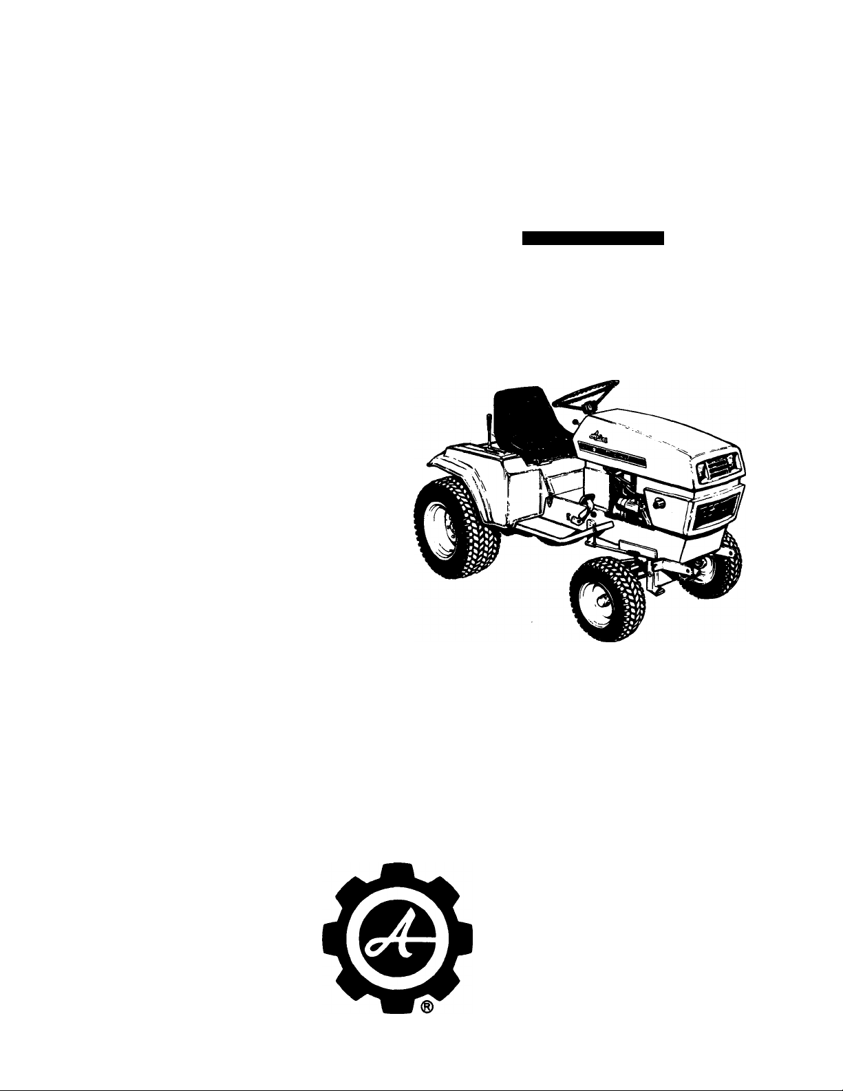
cAnimi
lOHHP
MODEL NO. 931014 S-10G
MANUAL LIFT W/FRONT AND
REAR ROCKSHAFT
SERIAL NO. 000101 AND UP
MODEL NO. 931013 S-14G
HYDRAULIC LIFT W/FRONT AND
REAR ROCKSHAFT
SERIAL NO. 000101 AND UP
PART NO. 31974
fianInllwMR
ARIENS COMPANY
BRILLION, WIS. 54110
Page 2
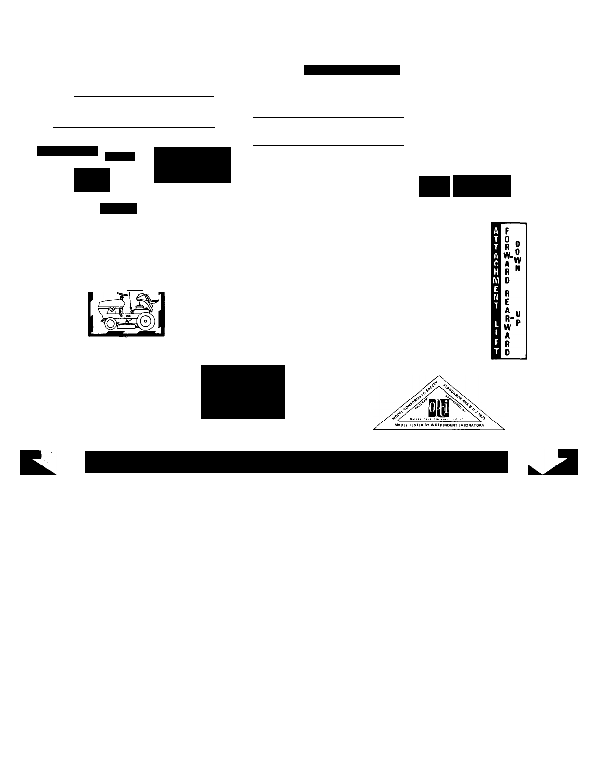
DECALS FOR MODELS 931013 & 931014 GEAR TRACTOR
WARNING
•BRAKES Will NOT STOP TRACTOlf >
<;UNLESS CLUTCH PEDAL IS DEPRESSED”
^3r"sHIFT selector is in NEUTRAL.Xji^
LIFT SELEQOR
REAR LIFT
‘FRONT AND
CENTER LIFT
78392
©CAUTION
KTOW [MSCOMNtC‘tl^l6
HVOWtK P«OK F«0"* TMOTO«,
ItekCMK FLOAT
PARKING BRAKE
UEPRL'SS BRAKE PEDAL
!HEN ENGAGE PARKING/'N^
BRAKt lOCK />G j
S-l-TE/y
S-14G R.H. 78374 /
S-14G L.H. 78375 /
S-10G R.H. 78363 /
S-10G L.H. 78364 i
@c^
L.H. 78362
R.H. 78361
LIFT
SELECTOR
78278
78373
DEPRESS BRAKE PEDAL
THEN ENGAGE PARKING
BRAKE LOCK.
A
READ ALL DECALS AND FOLLOW
DIRECTIONS CAREFULLY.
ENGAGED
► DISENGAGED
78311
INSTRUCTIONS FOR SAFE OPERATION
1. Know the controls and how to stop quickly. READ THE
OWNER'S MANUAL.
2. Do not allow children to operate the vehicle. Do not allow
adults to operate it without proper instruction.
3. Do not carry passengers. Keep children and pets a safe dis
tance away.
4. Clear the work area of objects which might be picked up
and thrown.
5. Disengage all attachment clutches and shift into park
before attempting to start the engine.
78340
S-10G ONLY
78226
9. Take all possible precautions when leaving the vehicle un
attended, such as disengaging the power take-off, lowering
the attachment, shifting into park, setting the parking brake,
stopping the engine, and removing the key.
10. Do not stop or start suddenly when going uphill or down
hill. Mow up and down the face of steep slopes: never across
the face.
11. Reduce speed on slopes and in sharp turns to prevent
tipping or loss of control. Exercise extreme caution when
changing direction on slopes.
12. Stay alert for holes in the terrain and other hidden hazards.
6. Disengage power to attachment, stop the engine and place
shift lever to"Park-Start"position before leaving the operator's
position.
7. Disengage power to attachment and stop the engine before
making any repairs or adjustments.
8. Disengage power to attachment when transporting or not in
use.
13. Use care when pulling loads or using heavy equipment.
a. Use only approved drawbar hitch points.
b. Limit loads to those you can safely control.
c. Do not turn sharply. Use care when backing.
d. Use counterweightls) or wheel weights when suggested,
in the owner's manual.
14. Watch out for traffic when crossing or near roadways.
2-
Page 3
DECALS FOR MODELS 931013 & 931014 GEAR TRACTOR
Awarning]
I Grasp handle, not chain.
78282
S-10 G ONLY
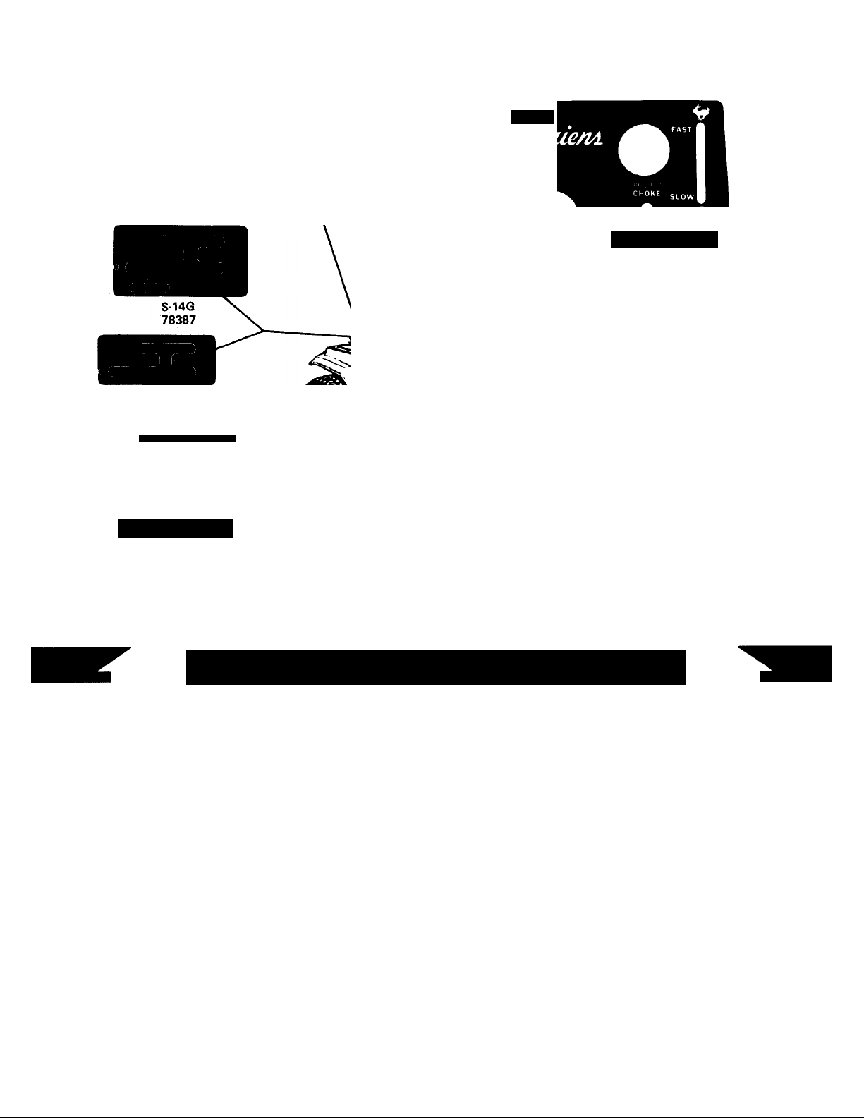
S-10G
78388
P , I ii FR T-(,T R
LIGHTS IMPL POWER
DASH PANEL - 78341
%RTiMG PROCEDURE
+ CAUTION
CERTFIE CONFORME AU REGLEMENT CANADIEN SUR LE BROUILLACE RADIOELECTRIQUE
78367
BE AWARE OF SAFETY DECALS
15. When using any attachments, never direct discharge of
material toward bystanders nor allow anyone near the vehicle
while in operation.
16. Handle gasoline with care—it is highly inflammable.
a. Use approved gasoline container.
b. Never remove the cap of the fuel or add gasoline to a
running or hot engine, or fill the fuel tank indoors. Wipe
up spilled gasoline.
c. Open doors if the engine is run in the garage—exhaust
fumes are dangerous. Do not run the engine indoors.
17. Keep the vehicle and attachments in good operating con
dition, and keep safety devices in place.
18. Keep all nuts, bolts, and screws tight to be sure the equip
ment is in safe working condition.
^ 19. Never store the equipment with gasoline in the tank inside a
building where fumes may reach an open flame or spark. Al
low the engine to cool before storing in any enclosure.
^CAUTION
RELEASE LIFT ASSIST SPRING
BEFORE DISCONNECTING
I ATTACHMENT FROM TRACTOR
78281
S-10 G ONLY
COMPLIANCE WITH CANADIAN RADIO INTERFERENCE REGULATIONS CERTIFIED
REPLACE SPARK PLUG WITH RESISTOR SPARK PLUG ONLY !
REMPLACER LA ROUGIE PAR UNE ROUGIE A RESISTANCE SEULEMENT I
78400
(UNDER HOOD, NEXT TO SPARK PLUG)
20. To reduce fire hazard, keep the engine free of grass, leaves,
or excessive grease.
21. The vehicle and attachments should be stopped and in
spected for damage after striking a foreign object, and the
damage should be repaired before restarting and operating
the equipment, see numbers 6 & 7 opposite page.
22. Do not change the engine governor settings or overspeed the
engine.
23. When using the vehicle with mower, proceed as follows:
a. Mow only in daylight or in good artificial light.
b. Never make a cutting height adjustment while the engine
is running if the operator must dismount to do so.
c. Shut the engine off when removing the grass catcher or
unclogging chute.
d. Check the blade mounting bolts for proper tightness at
frequent invervals.
24. Check the grass catcher bags frequently for wear or. de
terioration. Replace with new bags for safety protection.
I
Page 4
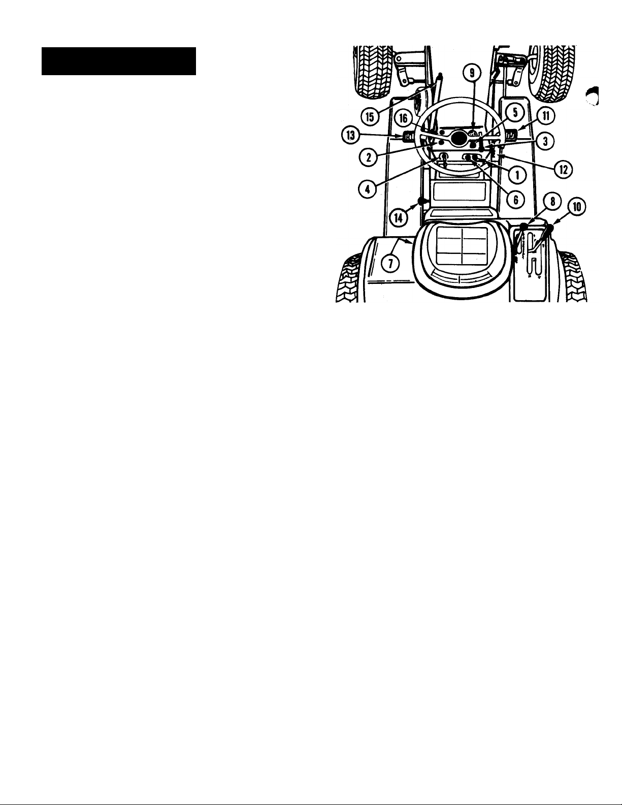
CONTROLS
Implement Power Control Switch (Figure 1).
Pull the switch out (ON) to engage the electro
magnetic clutch to drive the mower and front mount
ed attachments.
NOTE: This switchQ must be pushed in (OFF) to
disengage the drive before the engine will start or to
allow engine to keep running if the operator gets
off the seat.
©
Implement Power Indicator Light (Figure 1). This
light glows red when the implement power control
«witch (T) is pulled out to indicate that the mower
or front mounted attachment is engaged.
©
©
©
©
©
©
©
Throttle Lever (Figure 1). Raise the lever to in
crease engine speed. Lower the lever to decrease
engine speed.
Ignition Switch (Figure 1). Turn the key fully
clockwise to start the engine and release when the
engine starts. Turn the key counterclockwise to stop
the engine.
Choke Control (Figure 1). Pull choke control out
when attempting to start a cold engine or when
starting during cold weather. When engine starts,
gradually push choke in. Normally, it is not necessary
to use the choke when starting a warm engine.
Light Switch (Figure 1). Pull the switch out to
turn on the front and rear lights. The ignition key
must be turned on before the lights work.
Seat Safety Interlock Switch (Figure 1) This
switch, located in the seat, is closed by the operators
weight. If the operator leaves the seat for any
reason while the PTO is "ON" or the shift lever
is not in "NEUTRAL" the PTO clutch and engine
ignition are both shut off. When the PTO is "OFF"
and the shift lever is in "NEUTRAL" leaving the seat
will not cause the engine to stop.
Hydraulic Lift (Figure 1) Model S-14G only).
This lever controls the hydraulic system used to
raise and lower attachments. The lever has four
positions - UP, HOLD, DOWN and FLOAT. The
normal out-of-use position is the "HOLD" position,
whereby the attachment will not raise or lower. When
it is desired to raise the implement, move the lever
to the "UP" position, to lower the attachment move
the lever to the "DOWN" position. Place the lever
in the "FLOAT" position to allow the attachments
to follow the ground contours.
Ammeter (Figure)). The ammeter indicates the
rate of battery charge or discharge. The indicator
should register on the (-)-) side of the dial when the
engine is running at any speed above a slow idle.
When the engine is idling or with a fully charged
battery, the ammeter may not show charge. Should
the ammeter register on the (—) side of the dial for
an extended period of time with the engine running,
it indicates the alternator is not charging the battery.
Check the battery connections or contact your dealer.
©
®
®
®
®
FIGURE 1
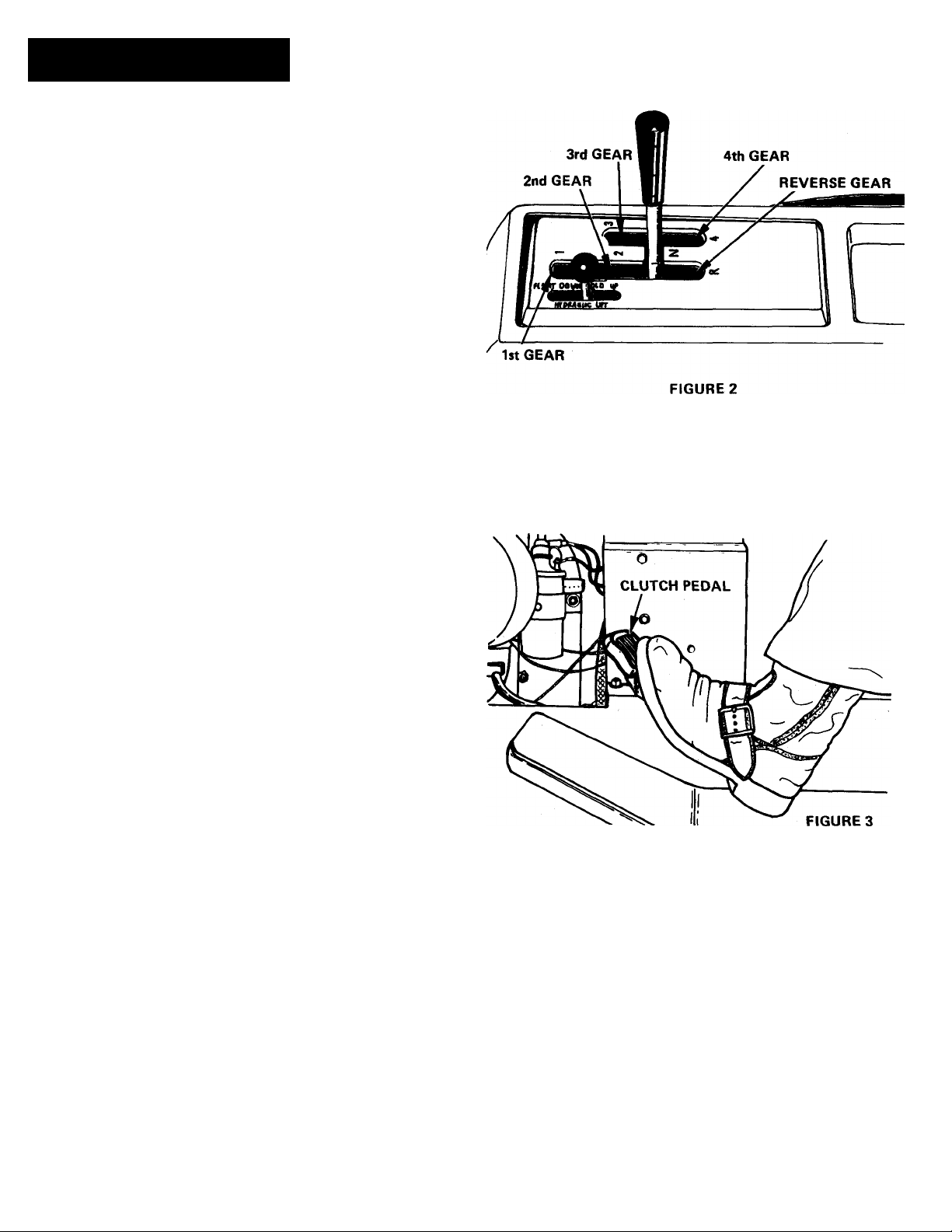
Gear Shift Lever (Figure 1) This lever selects any
of four forward speeds or reverse.
NOTE: This lever must be placed in the NEUTRAL
position before engine will start
Brake Pedal (Figure 1) When this pedal is depressed
the friction brakes will be applied to stop the tractor,
DEPRESS THE CLUTCH PEDAL ® BEFORE AT
TEMPTING TO STOP THE TRACTOR WITH THE
WHEEL BRAKES.
Parking Brake (Figure 1) The parking brake is a
latch that locks the brake pedal. To apply the park
ing brake, depress the brake pedal, flip up the parking
brake latch.® To disengage the parking brake,
depress the brake pedal and push down the latch.
Clutch Pedal (Figure 1) Depressing this pedal re
moves the idler pulley from the drive belt and dis
connects the engine from the drive train. Depress the
clutch to shift gears or before attempting to stop.
Lift Selector - Connects the attachment lift to
front/center or rear rock shaft. See page 12 and
Figure 23 for operation.
Manual Lift Lever (Figure 1) (Model S-10G only).
To raise attachment, press the thumb release, pull lever
rearward and lock in the raised position. To lower
attachment, press the thumb release and move lever
forward. This lever is spring loaded to the rear position
when the manual lift assist springs are engaged.
Implement Reset Button - Press to restart PTO in
the event the operator leaves the seat momentarily.
Under these conditions the PTO and engine ignition
will be shut off. If the operator sits down before the
engine stops revolving, the engine will restart, but
the PTO will not start until the reset button ® is
pushed. If the engine stops, the normal starting
procedure (Implement switch ®OFF; Shift lever
® in NEUTRAL) must be followed.
-4
Page 5
OPERATION
PRE-STARTING INSPECTION
Prior to starting the engine for each day's operation, the
following checks and services should be performed;
a. Check oil in engine crankcase. Add oil as required to
maintain proper level.
b. Check fuel supply. Use regular gasoline only.
c. Check air filter for excessive dirt. Clean as required.
d. Make visual check with regards to safety precautions,
obstructions, lubrication, and maintenance.
STARTING THE ENGINE
Use the following procedure to start the engine:
1. Place the gear shift lever in the "Neutral" position, shown
in Figure 2.
To run the tractor in REVERSE, shift to reverse gear.
NOTE: This is a safety feature. The engine wili not start
unless the shift lever is in neutral.
2. Be sure the Implement Power Control SwitchMJFigure
1„is pushed in (OFF). ^
NOTE: This is a safety feature. The engine will not start un
less the switch is off (pushed in).
3. Raise throttle lever^^Figure 1, to approximately 1/3
fast position.
4. Pull choke control^^Figure 1, all the way out if engine
is Cold. If engine iswarm, little or no choke may be
required.
5. Turn ignition key(|^Figure 1, clockwise all the way.
Release key as soon as the engine starts and push choke
button in. In cold weather it may be necessary to push choke
in gradually until engine warms up. If engine fails to start
bn the first attempt, turn key to off, wait a few minutes and
try again. Do not operate the starting motor continuously
for more than 30 seconds at a time.
Always allow engine to warm up before applying load.
In below freezing weather, allow engine to run at a fast idle
for a period of at least 5 minutes before using the tractor.
Serious internal damage to the engine could result if this
procedure is not followed.
OPERATING THE TRACTOR - GEAR SHIFT LEVER
When the gear shift lever is placed in the neutral position
the interlock switch is closed and the engine can be started:
the rear wheels are not in gear and the tractor may be pushed
around by hand as required after releasing the parking brake.
In general, best results will be secured by running the
tractor engine at full throttle while selecting the gear that
gives the desired ground speed. This insures that the attach
ment operates at maximum efficiency.
THROTTLE LEVER SETTING
When operating power driven attachments such as the
mower, snow thrower or the rotary tiller, run the engine at
full throttle unless the attachment operator's manual specifies
otherwise. Use the shift control lever, not the throttle lever
to select a safe travel speed when using power driven
attachments.
To run the tractor FORWARD, shift to one of the four
forward speeds. Speed for each gear (with engine at full
throttle) is shown below:
1st Gear .7 mph
2nd Gear 2.1 mph
3rd Gear 3.7 mph
4th Gear 5.4 mph
Reverse Gear 2.9 mph
Safe or proper travel speed depends on the attachment
used as well as the type of terrain or lawn, field and garden
conditions in which the tractor is operated.
-5-
Page 6
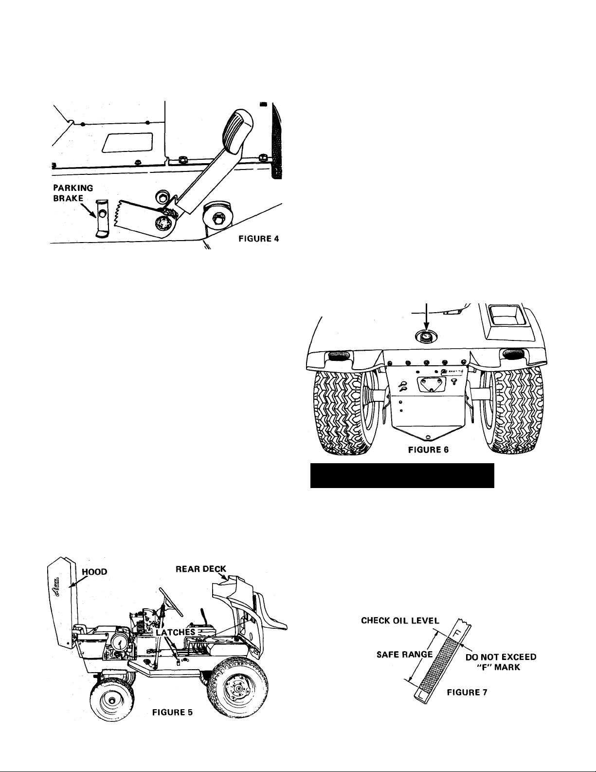
STOPPING THE TRACTOR
To stop the tractor, depress the clutch pedal @ and
depress the brake pedal (ñ) . Then place the shift lever in the
"Neutral" position and set the parking brake. Figure 4.
STOPPING THE ENGINE
Always use the following procedure to stop the engine:
1. Move the gear shift lever (j^ Figure 1, in "Neutral"
position, depress the brake pedal and set the parking brake
(Figure 4).
2. Disenga^ Implement Power Control Switch(^Figure 1,
and rear driven attachments.
CAUTION: Always shut off engine before raising the
rear deck. Be sure to lock the rear deck down with
A
A
FILLING THE TANK
Figure 6. Wipe the dust and dirt from around the cap before
removing it to prevent dirt from falling into the tank while
filling. Use an approved gasoline container and keep it clean.
fresh. Do not use premium gasoline. Do not mix oil with
gasoline. FILLER CAP
the latches provided before operating the tractor.
RAISING THE HOOD
The engine, battery and electrical components are readily
accessible by raising the hood, see Figure 5. To raise the hood
grasp each side and raise it ud and forward to its stop.
CAUTION: ALWA YSSHUT ENGINE OFF BEFORE
RAISING HOOD. NEVER TOUCH MUFFLER, EX
HAUST PIPE OR ENGINE UNTIL THEY HAVE
HAD TIME TO COOL AFTER OPERATING THE
ENGINE.
The fuel tank filler cap is located behind the seat, see
The fuel tank capacity is 4.5 gallons.
Use regular grade gasoline. Be sure the gasoline is clean and
ia!_p-
3. Lower attachment so that it is resting on the floor or
ground.
4. Lower the throttle lever Figure 1, and allow engine to
idle for a short period before turning it off.
5. Turn the ignition key^MFigure 1,
stop engine.
IMPORTANT — Remove ignition key before dis
mounting from tractor. This will prevent children
A
and inexperienced operators from starting the tractor.
RAISING THE REAR DECK
The transaxle and control linkage are readily accessible
by raising the rear deck, shown in Figure 5. To raise the
rear deck, place the shift control lever in the "Neutral"
position, release the two latches and raise the rear deck to
its stop.
counterclockwise to
LUBRICATION
ENGINE
Check the engine crankcase oil level daily or every 5
hours operation. It is essential that the oil level be maintained
in the "safe" operating range as shown in Figure? at all
times or serious engine damage could result.
To check the oil, stop engine and wipe all dirt and dust
from around the dip stick. Figures. Pull dip stick out, wipe
off the oil, re-insert dip stick and push it down tight. Pull
the dip stick out and observe the oil level. Add sufficient oil
of the proper viscosity to bring the oil up to the "fill"
(F) mark, see Figure 7. Be sure tractor is level when checking
oil.
DO NOT OVERFILL — Oil level must never exceed full mark.
Oil capacity of the engine crankcase is 4 U.S. pints.
-6
Page 7
Use AriensGard-N-Yardoil (SAE 10W-30 SE classification)
when using lawn and garden attachments. Use Ariens SnoThro oil (SAE 5W-20 SE classification) when using snow
removal attachments.
1. Drive tractor onto level ground.
2. Stop engine.
3. Wipe dirt from around the oil level filler plugs. See
Figure 10.
4. Remove filler plug. Oil level should level with the filler
plug hole, see Figure 10.
5. If necessary, use a small funnel to add sufficient MP-90
oil to bring the oil up to the proper level. Replace plug.
Be very careful to prevent dirt and foreign materials from
entering the transaxle when checking or adding oil.
CHANGE ENGINE OIL
When the tractor is new, the oil should be changed after
the first 5 hours of operation.
Under normal operating conditions, the oil should be
changed every 25 hours of operation. If extremely dusty or
dirty conditions prevail, change oil more frequently, use a
filter precleaner, consult Engine Manual.
Drain the crankcase by removing the drain plug, shown in
Figure 9 , and allow the oil to drain into a container. If
■k possible, run engine just prior to changing oil, as the oil will
^ flow more freely and carry away more contamination when
hot.
PIL FILLER
DRAIN
HDLE
FIGURE 10
HYDRAULIC LIFT DIL LEVEL (Model 931013only)
The hydraulic lift system should seldom require additional
hydraulic fluid unless a leak should develop. The hydraulic
fluid is stored in a reservoir/cooler located under the floor
panel in front of the seat. To check oil level, drive the tractor
on to level ground; move the hydraulic lift lever to the
"DOWN" position until the lift cylinder is fully retracted.
Remove the panel. The hydraulic reservoir is now exposed.
Clean away all dirt and remove the pipe plug at the front of
the reservoir. The oil level should be to the bottom of the
edge as shown in Figure 11. Rock the machine while looking
down the fill hole to be sure of the oil level position. If
additional oil is required, fill to the proper level with SAE
10W-30 Gard-N-Yard oil or equivalent by removing the top
plug, adding oil, and removing the front plug, again, to set the
oil level. Replace all pipe plugs, clean excessive dirt from
the cooler fins and replace floor panel.
NOTE: Bottom of engine shown. FIGURE 9
Replace drain plug. Remove dip stick and refill crankcase
with 4 U.S. pints of oil. Check oil on the dip stick to see that
the oil level is at the full (F) mark. Do not overfill.
TRANSAXLE OIL GRADE AND VISCOSITY
Ariens MP-90 Gear Lube or an equivalent oil meeting the
requirements of the American Petroleum Institute (A.P.I.)
should be used. Oil viscosity (weight) should be SAE 90 and is
I recommendedfor year-round use.
TRANSAXLE OIL LEVEL
The oil level in the transaxle should be checked every 25
hours of operation or monthly.
Use the following procedure to check the transaxle oil
level:
7-
RESERVDIR
DIL CHECK PLUG
DIL LEVEL
'EVEN WITH
BDTTDM DF
PIPE PLUG
'DIL FILL PLUG
FIGURE 11
Page 8
GREASE STEERING SYSTEM
Under normal conditions the steering system should be
lubricated every J50 hours of operation or quarterly whichever
occurs first. The following list of grease fittings are identified
in Figure 12. Wipe each fitting clean before and after
lubrication! Use a good grade of general purpose grease such
as Ariens Multi-Purpose grease.
Rotate steering wheel clockwise until the spindle arm con
tacts the axle stop and fill gearbox until grease is forced out
around the cam follower adjusting screw.
O Steering gearbox.
® Left king pin.
©Front L.H. Wheel
©Axle pivot
© Right king pin.
© Front R.H. Wheel
To clean the cartridge, remove the wing nut and the cover,
shown in Figure 13. and then remove the cartridge. Gently
tap the cartridge on a flat surface. Do not use any liquid
cleaner to wash cartridge. Do not use compressed air to re
move dirt as this may rupture the cartridge.
Examine cartridge carefully and replace it with a new one
if it is bent, crushed or if there is a noticeable loss of power.
Re-assemble cartridge and cover making sure it seats around
the back plate. Install wing nut and tighten finger tight.
A
IMPORTANT:
removed.
BATTERY SERVICE
Check the battery electrolyte level once each month. Add
distilled water to bring the level to the bottom of the split
ring in the filter tube of each cell.
Each spring and fall remove corrosion from the terminals
and apply a light coat of grease, to the terminals. Keep
battery cables securely tightened to terminals and be sure
battery is properly fastened down in battery holder at all
times. Keeping battery clean will prolong battery life.
Do not run engine with air fitter
FIGURE 12
MAINTENANCE
/VOTE THAT ALL ENGINE SERIAL NUMBERS
HIGHER THAN THOSE LISTED BELOW HAVE A
A
10 H.P. MODEL NO. K241S SERIAL NO. 7541007
14H.P. MODEL NO. K321S SERIAL NO. 8117916
HOUR METER
Ariens Garden Tractors models.
right side, just ahead of the dash panel. The hour meter will
record the actual time the engine operates. Keep a record of
hour meter readings in order to perform Maintenance and
Lubrication services at the recommended hourly intervals.
AIR FILTER SERVICE
When operating in extremely dusty conditions, check the air
filter daily. A precleaner is available. Consult the Engine
Manual.
GOVERNOR SETTING OF 3250 RPM, NO LOAD
(+ 75 RPM}. IDLE SET AT 1600 RPM, NO LOAD.
The hour meter is available as an optional accessory for all
The hour meter is located under the engine hood, on the
Check the air filter daily or every 5 hours of operation.
AIR FILTER CARTRIDGE
CAUTION: Storage batteries give off highly in
flammable hydrogen gas. Do not allow sparks or
flame near battery. Do not lay tools across battery
A
during winter months to prevent freezing. When water is
added during freezing weather, run the engine at least one hour
to thoroughly mix the water and electrolyte.
cable is connected to the negative (—) terminal on the battery,
see Figure 14. Be sure the battery cable is connected to the
positive (+) terminal.
terminals which may cause a spark resuiting in an
expiosion.
Maintain the battery at full charge during storage and
When installing the battery, make certain that the ground
WING NUT
FIGURE 13
A
WARNING: Reversed battery cables or reversed
cables from a battery charger or booster battery can
cause damage to the regulator rectifier (Figure 16).
Always disconnect plug from the regulator rectifier
before using a charger, booster battery or when
electric welding is done on the tractor.
Page 9
LUBRICATION AND PERIODIC SERVICE SCHEDULE
Hours of Operation/
T- , ^ , Service Required
Time Interval
Every 5 Hours or Daily Check Engine Crankcase Oil
Service Engine Air Filter
Every 25 Hours or Monthly
Service Battery
Check Tire Pressures
Check Transaxle Oil Level
Change Engine Oil
Clean Park Lock Assembly
Grease Steering System
The engine is air cooled. Air must circulate freely around
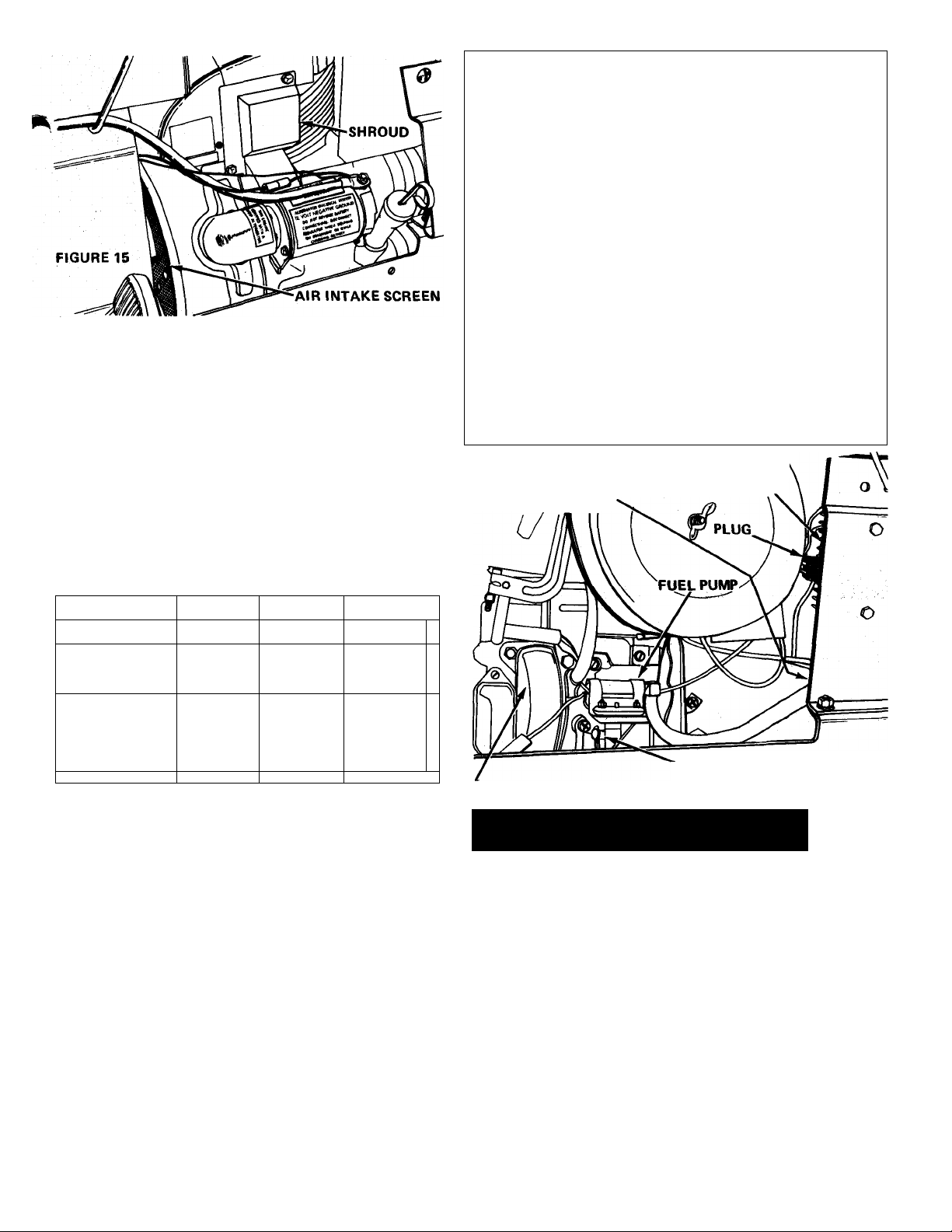
the engine from the air intake screen shown in Figure 15 and
over the cooling fins in the cylinder head and block to prevent
overheating.
Every 50 hours of operation or quarterly check the air
intake screen. Wipe away any dirt or debris which has col
lected on the screen. Remove the shroud. Figure 15 and in
spect the cooling fins. Remove any dirt, or chaff accumulations
from the cooling fins with compressed air. Replace shroud.
TIRE PRESSURES
Check tire pressure at least once each month. Inflate
tires to pressures shown in the chart below. Use a low pressure
tire gauge for accurate readings.
TIRE SIZE
Front
16x6.50x8
Rear
23 X 8.50 X 12
23 X 10.50 X 12
Light Medium
(Lawn Work)
8 p.s.i.
(Lawn Work)
6 p.s.i.
LOADING
(Sno-Thro)
12 p.s.i.
(Rotary-Tiller)
8 p.s.i.
Heavy
16p.s.i.
10 p.s.i.
Every 50 Hours or Quarterly
Every 250 Hours or Yearly
NOTE: When tractor is new, change the engine oil after the
first five hours of operation.
FUEL FILTER IS
LOCATED UNDER
FLOOR PLATE
Clean Reservoir/Cooler Fins
Check Spark Plug
Clean Fuel Filter
REGULATOR
RECTIFIER
Keep tires properly inflated at all times. Over-inflation
will cause operator discomfort. Under-inflation will cause
short tire life. Always see that the tire valve caps are in place
and securely tightened to prevent air loss.
FUEL PUMP AND FILTER
The engine may fail to start due to lack of fuel at the
carburetor if the fuel pump shown in Figure 16 loses its
prime. This can occur when the fuel tank is run dry or may be
due to evaporation of fuel from the system after a storage
period. In either case, make certain there is fresh fuel in the
tank and operate the priming lever on the fuel pump several
times to start fuel flow.
If a faulty fuel pump is suspected, see your Ariens dealer.
When dirt or other foreign material is allowed to enter the
fuel tank it will collect in the fuel filter shown in Figure 16.
This will eventually cause fuel stoppage. The filter can be dis
assembled and cleaned.
PRIMING LEVER
IGNITION BREAKER POINT COVER FIGURE 16
ADJUSTMENTS
CAUTION: ARIENS RECOMMENDS THE CUS
TOMER CONSULT HIS LOCAL ARIENS DEALER
A
SEAT ADJUSTMENT
positions. To adjust seat position, grasp seat back and raise
seat. Slide the seat forward or backward as required to the
most comfortable position.
FRONT WHEEL TOE-IN ADJUSTMENT
proper steering and to reduce tire wear. The proper amount
of toe-in is when the front of the wheels are 1/16" to 1/8"
closer together than the rear of the wheels, measured at the
horizontal centerline of the rim flange.
-9
FOR PROPER ADJUSTMENTS. THE USE OF
IMPROPER TOOLS OR INCORRECT ADJUST
MENT COULD RESULT IN DAMAGE TO THE
TRACTOR OR INJURY TO OPERATOR.
The seat is adjustable forward and backward to seven
Proper toe-in of the front wheels is necessary to assure
Page 10
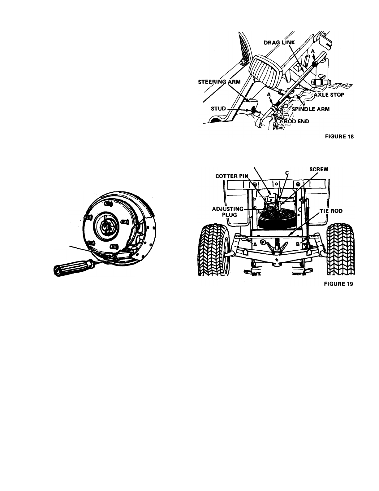
If the steering develops a wandering characteristic or if
excessive tire wear develops, the toe-in of the front wheels
should be checked. If the toe-in is incorrect, adjust as follows;
1. Loosen jam nuts A and B, Figure IB.
2. Rotate tie-rod until toe-in is correct. Shorten tie-rod to
decrease toe-in. Lengthen it to increase toe-in.
3. Tighten jam nuts A and B after correct toe-in is obtained.
BRAKE ADJUSTMENT
The tractor brakes will require adjustment when the brake
pedal depresses over two inches. To adjust the brakes proceed
as follows:
1. Block up the rear of the tractor with the wheels off the
ground.
2. Remove the wheel lug nuts and remove the wheel.
3. Insert a screw driver in the slot in the brake drum (See
Figure 17)' and tighten the star washer until the brakes are
snug and the drum does not turn. Back off the star washer
one full turn.
4. Replace the wheel and secure with the wheel lug nuts.
Repeat adjustment on the opposite wheel.
STEERING GEAR
CAM FOLLOWER
ADJUSTING
STAR WASHER
FIGURE 17
STEERING GEAR ADJUSTMENT
If loose play is noticed in the steering system after con
tinued use, the steering gear may require adjusting to remove
excessive backlash between the gears. Adjust steering gear
using the followirig procedure:
1. Raise front of tractor so that the tires clear the ground.
2. Remove cotter pin identified in Figure 19.
3. Loosen jam nut C, Figure 19 and turn adjusting screw out
(counter-clockwise) IVi turns.
4. Tighten adjusting plug. Figure 19, to 10-14 ft. lbs. of
torque.
5. Rotate adjusting plug out slightly to align nearest slot in
the plug with the cotter pin hole and reinstall the cotter pin.
6. Hold jam nut and turn adjusting screw. Figure 19,
clockwise (in) until backlash is removed from steering wheel.
DO NOT FORCE ADJUSTING SCREW. Torque jam nuts
35-45 ft. lbs. while holding adjusting screw in position.
7. Turn Steering wheel from lock to lock and check for
binding or dragging inside gearbox. If any binding or
dragging exists, it will be necessary to loosen the adjusting
screw and/or the adjusting plug slightly until steering wheel
turns freely with no loose play.
STEERING STOP ADJUSTMENT
When making a full right hand turn, the spindle arm
should contact the axle stop as shown in Figure 18. When
making a full left hand turn, the left spindle arm should
contact the left axle stop. Proceed as follows to adjust the
steering stops.
1. Rotate front wheels to the right until right spindle arm
contacts the axle stop. Figure 18.
2. Remove drag link rod end from steering arm. Figure 18,
and loosen jam nuts A.
2a. Rotate steering wheel clockwise until steering gear
bottoms. Back off 1/8-1/4 turn counter clockwise.
3. Rotate drag link as required while preventing the loose rod
end from turning until the stud is approximately V: hole to
the rear of hole in steering arm, Figure 18. Be sure axle stop
contacts steering arm.
4. Reinstall rod end stud in steering arm and tighten jam
nuts A.
5. Rotate wheels completely to the left. The left spindle
arm should contact left axle stop. If it does not, repeat step j|
2 and shorten drag links slightly until both spindle arms contact their respective axle stops when making full turns In '
either direction.
10-
Page 11

REAR WHEEL TREAD ADJUSTMENT
The rear wheels are normally assembled in the narrow
tread position, shown in Figure 20. The wheels can be turned
on the hubs for a wider tread. The wide tread provides greater
stability on hillsides and on rough terrain.
Remove the wheel lug nuts, turn the wheels around with
the valve stems inward and re-assemble on the hub.
NARROW WHEEL TREAD SETTING
10.50 X 12 TIRES SHOWN)
• *er
I A Al c
NARROW
23 X 10.50 X 12 = 32%
0 WIDE
23 X 10.50 X 12 = 35'/4
FIGURE 20
If Chevron tread tires are used, remove the wheel lug
nuts and re-assemble the wheels on opposite sides of the
tractor with the valve stems turned inward. Interchanging
the wheels is necessary to maintain proper direction of
rotation for traction tires.
The center rock shaft pan flotation spring, shown in Figure
24 provides mower flotation. The tension on the spring can be
increased or decreased by presetting the latch bar to a dif
ferent notch when the pan is fully raised. The bottom notch
provides the greatest flotation.
The front/center or rear rock shaft is selected for operation
by the manual lift lever by the lift selector knob. Figure 23.
To change selection, locate selector knob to proper end and
rotate the mechanical lift lever past the last notch to the
overtravel area. This allows the selector latch to change po
sition. This allows a rear attachment to be used without re
moving the front/center attachment, or vise versa.
HYDRAULIC LIFT OPERATION
The hydraulic lift system is standard equipment on the
S-14G.
The hydraulic control lever is located on the control
console, shown in Figure 2. It is a four position lever to per
form four functions, UP, HOLD, DOWN and FLOAT. The
normal out-of-use position is the "HOLD" position whereby
the attachment will not lower or raise. When it is desired to
raise the attachment, the lever is pulled to the "UP" position
and the cylinder is actuated to lift the attachment. When the
lever is moved to the "DOWN" position, the oil pressure in
the cylinder is reversed and the cylinder forces the attachment
down.
When an attachment is being used which is designed to fol
low ground contours, the lever should be placed in the
"FLOAT" position. The cylinder is then free to move as the
attachment position requires.
Figure 25 shows the components of the hydraulic lift
system. The hydraulic pump supplies the oil flow from the
oil reservoir/cooler. Oil flow to and from the cylinder is con
trolled by the valve.
MANUAL LIFT OPERATION
Manual Lift Lever {Figure 21) (Model S-10G only). To
raise attachment, depress thumb release and pull lever to the
rear until the locking pin engages in the proper quadrant
notch to obtain desired attachment height. To lower attach
ment, depress thumb release and push lever forward. After the
attachment touches the ground the force from the lift assist
springs will resist the forward motion of the lift lever. The
amount of resistance is relative to the spring adjustment.
The two springs shown in Figure 24 are used to provide
lift assist. The tension on these springs should be adjusted
using the chains shown in Figure 22, so the front mounted
attachments can be raised or lowered with the lift lever by
the operator.
CAUTION: WHEN ADJUSTING CHAIN TENSION
ALWA YS GRASP CHAIN HANDLE FIRML Y (NOT
A
and lower the rotary mower. This rock shaft is connected to
the manual lift lever through the link. The connection at the
rock shaft is made through the slotted hole which allows
the rock shaft to move up and down when in the lowered
position, allowing the mower to float without causing the lift
lever to move.
THE CHAIN) AS CONSIDERABLE TENSION IS ON
THE CHAIN AND INJURY TO THE HANDS
COULD RESULT.
The' center rock shaft shown in Figure 24 is used to raise
When the cylinder is extended or retracted, the bell crank
pivots and raises or lowers both the front and center rock
shafts at the same time through the front and center rock
shaft linkages shown in Figure 25. The connection to the
center rock shaft is made through the slotted hole which allows
the center rock shaft to move up and down, allowing the
mower to float independent of the flotation provision in
the hydraulic system.
MANUAL LIFT LEVER
ATTACHMENT HEIGHT CONTROL QUADRANT
o
FIGURE 21
The center rock shaft pan flotation spring shown in Figure
25 provides mower flotation. The torsion on the spring can be
increased or decreased by presetting the latch bar to a different
notch when the pan is fully raised. The bottom notch pro
vides the greatest flotation.
-11 -
Page 12

ADJUSTING CHAINS
FOR S10G MANUAL
LIFT, ASSIST SPRINGS
CAUTION - WHEN ADJUSTING CHAIN TENSION ALWAYS GRASP
CHAIN HANDLE FIRMLY (NOT THE CHAIN) AS CONSIDERABLE TENSION
A
IS ON THE CHAIN AND INJURY TO THE HANDS COULD RESULT.
HYDRAULIC LIFT REAR ROCK SHAFT
The rear rock shaft comes with a lift selector device so
that the front and center rock shafts can be operated indepefidentty of the rear rock shaft while utilizing only one
hydraulic cylinder. The alternately latched, split lift linkage
systeih holds the front and center rock shafts in their raised
positions while the rear rock shaft is operated by the cylinder
.or vice versa. This allows a rear mounted attachment to be
used without removing the front or center mounted attach
ments and vice versa.
FIGURE 22
To make the rear rock shaft operational, move the hy
draulic control lever to the "UP" position and hold it there
until the cylinder is fully extended. Place the selector knob in
the front notch (Figure 23).
To make the front and center rock shafts operational,
move the hydraulic control lever to the "UP" position and
hold it there until the cylinder is fully extendi. Place the
selector knob in the rear notch as shown in Figure23.
IN REAR NOTCH - FRONT AND CENTER ROCKSHAFTS
c
<
Page 13

STORAGE
FIGURE 25
PREPARATION FOR STORAGE
1. Remove all oil, grease and dirt from engine and trans
mission.
2. Clean the tractor exterior and tires thoroughly, removing
all mud, dirt and grease.
3. Touch up all unpainted and exposed areas with paint to
prevent rust.
4. Change engine oil.
5. Disconnect fuel line at fuel filter and drain fuel tank. Run
the engine until the fuel is exhausted from the system.
Drain the carburetor by loosening the nut on the bottom of
the carburetor bowl. Clean the fuel filter.
6. Remove and clean the battery. Check electrolyte level and
have battery fully charged. Store battery in a cool, dry place
where it will not freeze.
•
7. Remove the spark plug and pour one tablespoon of SAE
30 oil into the cylinder. Turn engine over manually at least
two revolutions.
8. Re-gap spark plug. Replace if required.
9. Grease the steering system.
10. Store tractor in a cool, dry place to reduce tire de
terioration. Block up tractor to take the weight off the tires.
11. Inspect tractor for visible signs of wear, breakage or
damage. Order any parts required and make necessary re
pairs to avoid delays when starting next season.
NOTE: Your authorized Ariens dealer is trained and equipped
to service your tractor. A periodic check-up by your dealer
will help to reduce your maintenance costs.
PREPARATION FOR USE AFTER STORAGE
1. Replace battery and check electrolyte level.
2. Fill fuel tank with fresh, clean regular gasoline.
3. Check transmission oil level.
4. Check tire inflation.
5. Check oil level in hydraulic reservoir - Model 931013 only.
-13-
Page 14

FRAME, STEERING, FRONT WHEEL
GEAR MODELS 931013 & 931014
SEE PAGE 15 FOR
INTERNAL PARTS
I
- 14-
Page 15

FRAME. STEERING, FRONT WHEEL
GEAR MODELS 931013 & 931014
REF
PART
NO.
N0.
031084 STEERING WHEEL 1
1
059004 CAPSCREW, HH,3/8 - 16x 1
2
631131
3
4
031173
5 031038
031049 PAD
6
7
531065 FRAME (for Model931014)
531066
064063 WASHER
8
10 054101 BALLBEARING
11 065098 LOCKNUT, 3/8" 2
031020
12
031262
13
14
064126
15 031130
065105 NUT, Hex Jam 1/2"-20 UNF (L.H.)
16
17 031929
065044 NUT, Hex Jam 1/2 -20 UNF (R.H.)
18
031129
19
031175 STEERING ARM 1
20
21
531011
22 055091 BUSHING
031140
23
075067 WASHER, 1-1/32 ID x 1-3/4 OD. x .060 Thick 2
24
031552 SPINDLE, L.H.
25
26 031169
27 031551
28 064029
29 054121
631084
30
31
32 071103 TIRE 1
33 067024 PIN, cotter 1/8 X 3/4
DESCRIPTION
STEERING GEAR ASS'Y 1
BRACKET, Mounting 1 37
CLAMP
FRAME (for Model 931013)
BEARING FLANGE
STEERING ARM
WASHER, 2" OD. x 9/16" ID x .135 Thick
BALL JOINT, L.H.
DRAG LINK, 11-1/8" Long 1
BALL JOINT, R.H.
FRONT AXLE W/BUSHING, ZERKS
SPINOLE COLLER,L.H. 1
ROD, 18-1/2" Long
SPINDLE, R.H.
WASHER 2
RAOIAL'BEARING
FRONT WHEEL ASS'Y - Consists of
071110 RIM 1
NO
REQ'D
2 35
1 38
1
1
1
AR
1
2
1
1
2
2
6
2
1
4
1
1
1
4 63 010353 ZERK FITTING
2
2
REF
Part
NO.
NO.
34
031568
059154
36 063006
029013
029024 WASHER, Spring
029014 LATCH R.H.
39
40 029015
41
065117 NUT, Hex Jam, 5/8"
42
059145
43 063021
44
064008 WASHER, Flat, 3/8"
45
065018
064002 WASHER, Flat, 5/16"
46
47
063003
48 065015
50 059022
51 062015
52 059146
53
065121
54
065042
55 059152
56 064131
57
022093 ZERK FITTING
58 031121
058037
59
058004 ROLL PIN
60
61 064043
62 031083
069094
64
65
031031 COVER
031734
66
67
063030
DESCRIPTION
WASHER, SPECIAL
CAPSCREW, 3/8 X 6 X 3/4 Grade 5
LOCKWASHER, 1/2"
LOCK STOP
LATCH L.H.
CAPSCREW, HH, 3/8x1" GR.5
LOCKWASHER, 3/8"
NUT, Hex, 3/8"
LOCKWASHER, 5/16"
NUT, Hex, 5/16"
CAPSCREW, HH, 5/16x 3/4
BOLT, Carriage, 5/16 x 1"
CAPSCREW, HH, 1/2 x 1-1/4" GR. 5
LOCKNUT
LOCKNUT
CAPSCREW, HH, 3/8 X 2-1/2
WASHER, Flat, 3/8"
ZERK FITtlNG,90°
ROLL PIN, 1/4 X 1-3/4
WASHER
CAP
CLAMP
BRACE
LOCKWASHER EXT.
NO
REQ'D
2
2
1
2
4
1
1
1
7
8
4
5
2
8
5
3
7
1
5
2
1
2
2
1
1
2
2
1
2
1
1
1
2
STEERING GEAR ASSEMBLY
*Not Available.
Order Complete
Steering Gear
Assembly No. 631131
REF.
NO.
1
2
3
4
5
6
7
8
9
10 031699 SEAL 1
11
12
13
14
15 064158
PART
NO.
031694
055099
075078 DUST COVER
067018 COTTER PIN, 1/8" X 1/2" 1
031695
064159
531042
065016
031696
031698 RETAINER, Seal 1
031697
031263
065119
DESCRIPTION
HOUSING 8i TUBE ASSEMBLY 1
BUSHING 1
PLUG, Adjusting
WASHER, Special
BEARING KIT 2
NUT, Hex Jam, 3/4" 2
LUBE FITTING, 1/4" Straight
STUD, Lever
LEVER & SHAFT
NUT, Hex Jam, 9/16"
WASHER, Special
15
NO.
REQ'D
1
1
1
1
1
1
1
1
Page 16

REAR DECK. SEAT. DASH SUPPORT. RUNNING BOARD
GEAR MODELS 931013 & 931014
Page 17

REAR DECK. SEAT. DASH SUPPORT. RUNNING BOARD
GEAR MODELS 931013 & 931014
REF
PART
N0.
N0.
1
031713 REAR DECK
2
031132
3
031133
4
031197 SEAT SUPPORT
5 031134
6 069102
7
031798
8 031135
9
031131
DESCRIPTION
SEAT BRACKET, right hand 1
SEAT BRACKET, left hand
SUPPORT
CABLE, 24"
BOTTOM COVER
ROD, 12-5/16” Long 2
CHANNEL 2
NO
REQ'D
12 031711 CHANNEL 2
13 031710
14
031094
SEAT
CLAMP
15 031517 CHANNEL 2
16 031055 SUPPORT 1
17
531070
531071
18
062034 BOLT, Carriage, 5/16 -18 x 3/4
19
531073
531072
20
031569
21 031019
22
075066 GROMMET
23
031028
24
531068 OASH SUPPORT - Model 931014
CONSOLE DECK-Model 931014 1
CONSOLE DECK-Model 931013
FLOOR PLATE-Model 931013
FLOOR PLATE-Model 931014
RUNNING BOARD
SPACER
HINGE
531069 DASH SUPPORT - Model 931013
25
065032
26
074044
27
031086
28
070015
29
059069
30
065042
31
062011
32
069094
33
031784
34
031089
NUT, Hex, 1/4"
SCREW, Self-Tapping, No. 10 x 3/8"
BATTERY TIE OOWN 1
FLANGE WHI2L0CK SCREW, 5/16-18
X 1/2 4
CAPSCREW, HH, 5/16x1-1/4
LOCKNUT, Hex, 5/16"
BOLT, Carriage, 5/16 X 3/4
"J" CLAMP
SUPPORT BRACE
ROD, Battery Tie Down
1 35
1 37
1
1
1
38 059150
39
40 064123
1 41
42
43
44
1
2
45 067003
49 059023
50 063021
51 061012
52 063026
1
2
1
1
1
4
4
\
1
1
3
4
S3
54
55 031556
56
57
58 063002 LOCKWASHER, 1/4"
59
60
61 070015 FLANGE, Whitlock Screw
62 031709
63
65 065099
69
4
4
4
4
1
2
REF
PART
NO.
NO.
065070
031701 BATTERY TRAY
36
DESCRIPTION
NUT, Crown
075065 GROMMET
CAPSCREW.HH, 1/4x1 1/2
061042
SCREW, Machine, Truss H, 5/16 x3/4- -
WASHER, Flat, 5/16
063003
065015
074043
064127
L0CKWASHER,5/16
NUT, Hex, 5/16
SCREW. Self-Tapping, HH, No. 10 x 1/2"
WASHER, Flat, 1/4"
PIN, Cotter, 1/16 X 1/2"
CAP SCREW, HH, 3/8" X 3/4"
LOCKWASHER,3/8"
SCREW, Machine R.H. No. 10-32 x 1/2"
LOCKWASHER, No. 10
065026
074017
NUT, Hex, No. 10-32 4
SCREW, Self-Tapping, HH, 5/16 x 3/4
X WASHER
064002 WASHER, Flat, 5/16
061039
SCREW, Machine, Truss H, 1/4 x 3/4
065089 SPEED NUT
064123 WASHER
HOSE
075044
64 062015
GROMMET
CARRIAGE BOLT - Model 931013 only)
NUT
065040
70
010289
•
LOCKNUT
EYE BOLT
NO
REQ'D
2
1
1
1
4
4
10
10
6
6
4
4
4
5
4
5
1
17
1
2
4
2
4
1
1
1
1
2
1
17
Page 18

HOOD, GRILL, HEADLIGHTS AND HEAT SHIELD
GEAR MODELS 931013 & 931014
^
-------
REF
PART
NO.
NO.
1
531056
531055
4
031046
5
031139
031138
6
7 031185 HINGE, Right Hand
8 031186
9 031145
075064 GROMMET 2
10
11 031986 MUFFLER SHIELD, S-10G .S-14G
12
075066
069094 "J” CLAMP
13
14
031093
15 061039 SCREW, Machine, Truss H, 1/4 X 3/4 5
064127
16
17
063002 LOCKWASHER, 1/4" 5
18
065032 NUT, Hex, 1/4"
^
DESCRIPTION
HO0D,S-10G
H00D,S-14G
GRILL
SIDE, Right Hand
SIDE, Left Hand
HINGE, Left Hand 1
SPACER, 3/4"
GROMMET 1
LATCH
WASHER, Flat, 1/4" 5
----
(j?)
NO.
RED'D.
M)
REF
NO.
1
1
1
1
1 24
1
2
1
2
1
5
20
21
22
23
(22
PART
NO.
064008
062032
062013
063021
065018
061042
25
064123
26
29
075058 HOOD STOP
30 063018
DESCRIPTION
WASHER, Flat, 3/8"
BOLT, Carriage 3/8" x 2
BOLT, Carriage, 3/8" x 1 ■
LOCKWASHER, 3/8"
NUT, Hex, 3/8"
SCREW, Machine, Truss H, 5/16 x 3/4
WASHER, Flat, 5/16"
STAR LOCKWASHER
NO.
REO'D.
6
2
6
8
8
2
2
2
2
18-
Page 19

MUFFLER, FUEL LINES & TANK
GEAR MODELS 931013 & 931014
I
I
PART
REF
NO.
NO.
031155 MUFFLER
1
2 031266
031082
3
. 4
5 070039
031180
6
030020
8
029108 FILTER, Fuel
9
069094
10
DESCRIPTION
CLAMP
BRACKET, Muffler
ENGINE, S-10, Kohler No. 46725D
ENGINE, S-14 Kohler No. 321-S 60238
LOCKNUT, Special
PIPE, Nipple
HUSt bb'^
"J"CLAMP
*0rder Replacement Engine and Replacement Engine Parts From Your
Nearest Kohler Service Central
to
••
0
1
1 1 13
1 1
1 1
1
1 1
1
1 1
1 1
1
REF.
N0.
i
J4
15
1
1
20
22
1
-19-
PART
NO.
031818
031904 FOAM 6" Long
031819
16
031190
17
063021
18 065018 NUT, Hex, 3/8 4 4
059151
19
029172
069053
DESCRIPTION
TANK, Fuel
GAS GAUGE 8> CAP
ELBOW, Street, 45°, 1-1/4
L0CKWASHER,3/8 4
CAPSCREW, HH, 3/8 x 1-1/2 GR.5
HOSE CLAMP
TIE 1 1
o
CO
9>
1
AR
1
444
iO
o
<o
o>
AR
1
1
1
4
4
Page 20

HYDRAULIC LIFT AND FRONT ROCK SHAFT
GEAR MODEL 931013 ONLY
-20-
Page 21

HYDRAULIC LIFT AND FROISIT ROCK SHAFT
GEAR MODEL 931013 ONLY
REF
PART
N0,
NO.
1
531067
• 2
031170
031779
3
031692
4
031778
5
031058
6
7
031780
8
059050
064127
9
10 031051
DESCRIPTION
CYLINDER ASS'Y (includes adapters) 1
VALVE
HOSE, 20" Long, Pump to Valve
HOSE, 2714" Long, Valve to Cylinder
HOSE, 19" Long, Valve to Reservoir
HOSE, 2414" Long, Valve to Cylinder
ADAPTER, 1/4 to 9/16,45°
CAPSCREW, HH, 1/4 x M/2
WASHER, Flat, 1/4" 2
PIN, Clevis
NO
REQ'D.
11 031063 BELL CRANK 1
068061 PIN
12
031500
13
14
067029
16 063002
LINK 1
HAIRPIN COTTER 1
LOCKWASHER, 1/4"
16 031189 CONTROL ROO
17
075052
531005
18
KNOB
FRONT ROCKSHAFT
19 031015 CONNECTOR LINK
20
029011
21 065032
067004
22
067006
23
24 067026
031014 BRACE
25
031076
26
064115
27
28 064009
058053
29
062005
30
065039 LOCKNUT, Hex, 3/8
31
32 063003
059134
33
34
059022 CAPSCREW, HH, 5/16x3/4
35 064002
065015
36
069094
37
38 031495
031634 ADAPTOR
39
40 031785
BEARING BLOCK
NUT, Hex, 1/4"
PIN, Cotter, 1/8 X 1 2
PIN, Cotter, 3/16 X M/4
PIN, Cotter, 3/16 X 1" 2
BRACKET
SHIM, .005Thick
WASHER, Flat, 3/4
GROOVE PIN, 1/4 X 3/4
BOLT, Carriage, 3/8 x 2-1/4
LOCKWASHER, 5/16"
CAPSCREW, HH, 5/16 X 1-1/4 gR.5 1
WASHER, Flat, 5/16
NUT, Hex, 5/16
J-CLAMP
ADAPTOR, 9/16
OIL RESERVOIR
REF
NO.
1
1
1
»* ^
1
PART
NO.
41
031787
42 030009
43
031789
031727
031794
45
1 46 031781
47
1
031783
2 48 031782
49 062011
059004
2
50
51 064078
1
3
1
1
1
1
4
6
1
1
1
4
1
1
4
4
6
52 063021
53
065018 NUT, 3/8-16
54
074027
55
074059
56 062012
57 064007 WASHER
58
001138 PIPE PLUG
59 066032
60
060008
61 031795 SHEAVE
031797
62
63 031788
64
072088
004226
65
66
030013
67
030011
68 030012
69 030014
70
065075
71
063019
72
030008
73 030010 CONNECTOR
3
7
2
1
1
1
1
DESCRIPTION
CIRCULATION COVER
FILLER COVER
GASKET RESERVOIR
PUMP HYDRAULIC
PUMP MOUNTING BRACKET
HOSE, 14" Pump to Reservoir
BRACKET
BRACKET, Mounting
BOLT, Carriage 5/16-18x3/4"
CAP SCREW, 3/8-16 X 1
WASHER
LOCKWASHER
TAPTITE 12
TAPTITE 2
BOLT, Carriage 1/4-20 x 3/4"
KEY 1
SETSCREW
ADAPTOR 1
ADAPTOR 3/8 to 9/16
BELT
PIPE PLUG
COVER
FITTING
OIL EXPANSION CUP
FIBER WASHER
NUT
LOCKWASHER
HOSE, 16" Long
*531041 Section Repair Kit Available
*531057 Spool Repair Kit Available
**531075 Pump Repair Kit Available for most
maintenance repairs.
NO
REQ'D.
1
1
2
1
1
1
1
1
2
4
4
4
4
1
1
1
2
1
1
1
1
1
1
1
1
2
1
1
1
21 -
Page 22

REAR BRAKE & CLUTCH ASSEMBLY
GEAR MODELS 931011&931012
Page 23

REAR BRAKE & CLUTCH ASSEMBLY PARTS
GEAR MODELS 931013 & 931014
REF
PART
N0.
N0
1
031679
2 031678 DUST SHIELD 2
3 531039
4
031680 PIVOT NUT
5
031682
6
083162
7
083161
8
083160
9 031763 CLUTCH ARM 1
10
031681
11
067032
12
031675
13 031677
14
064156 WAVE WASHER
15 031702
067001
16
031507 BRAKE LATCH
17
18 059001
064127
19
011091 SPACER, Bushing 1
20
21 065040
031935
22
031939
23
24 031940 ARM
25 031938
26 031808
27
064048
28 058040
031941
29
30
031509
31 059003 CAPSCREW, HH 5/16"
063004
32
DESCRIPTION
TORQUE, Spider 2
BRAKE SHOE (sold in sets of two only) 2
SOCKET, Adjusting Screw 2
SPRING, Adjusting Shoe
SPRING', Shoe Return, L.H. 2
SPRING,Shoe Return, R.H.
ADJUSTING SCREW, (star wheel) 2
HAIR PIN RETAINER 4
STRUTS. LEVER ASSEMBLY
PIN
RETAINER CLIP
PIN,Cotter3/32"x3/4"
CAPSCREW, HH, 1/4" X 3/4" 1
WASHER, Special
LOCKNUT, Hex, 1/4"
ROD
ARM
BRAKE ARM
BRAKE ROD
WASHER, Flat 3/8" 1
PIN, Drive 1/4" X 1-1/4"
BRAKE SHAFT 1 1
PLATE
LOCKWASHER,3/8"
NO
REQ'D
931014 931013
2
2
2
2
2
2
2
7
1
2
1
1
2
1
2
2
1
4
REF
NO.
2
2
2
2
2
2
2
2
1
2
4
2
2
2
2
7
1
1
1
1
1
2
1
1
2
1
1
2
2
2
4
33 062013
34
35
36 069113
37
38
39
40
41 063021
42
43
44 031505
45
46 059135
47
48 055095
49
50
51
52 025135
53 031936
54
55
56 064057
58
59
60 064062
61
62 031937
PART
NO
067006
031791
031762
031674
083122
013303
065018
075051
059030
058003 ROLL PIN
075055
064002
031504
065042
074046
031676
064043 WASHER
055095 BUSHING
055096 BUSHING
631107
631108 L.H.BRAKE ASSEMBLY 1 1
DESCRIPTION
BOLT, Carriage 3/8" x 1" 4
PIN, Cotter 3/16" X 1-1/4"
L.H. PEDAL
L.H. PEDAL
CLUTCH CABLE
BRAKE DRUM
SPRING
CLEVIS PIN
NUT, Hex 3/8"
LOCKWASHER,3/8"
PEDAL PAD
CAP SCREW, HH 3/8" X 2-1/4"
ARM, Brake
CAP SCREW, 5/16-18x3/4
GROMMET
BUSHING
WASHER, 5/16"
R.H. PEDAL
LDCKNUT, Hex 5/16"
SPACER
BAL. LINK 1
FLANGE WHIZLDCKSCREW 8
PARK BRAKE LEVER
WASHER, 5/16"
WASHER
R.H. BRAKE ASSEMBLY
CLIP
NO
REQ'D
931014 931013
1
1
1 1
2 2
2 2
2
5 5
1
2 2
1
1
1
1
2
1
1
1
3
1
2
2
7
1
AR
AR
1
1
4
1
1
2
1
1
1
1
1
2
1
2
1
4
2
1
8
2
2
7
2
1
1
23
Page 24

MAIN DRIVE
GEAR MODELS 931013 & 931014
•24
Page 25

MAIN DRIVE
GEAR MODELS 931013 & 931014
REF
FART
NO.
NO.
1
2
031771 BRACKET
3
4
031821 STRAP
5 031766 SUPPORT -L.H. Axle
031685
6
7
031728
8 062028 BOLT, Carriage 3/8-16 x 1 Gr. 5
9
064043
10 060032
11
083168
12 031956
13
031958
14 031743
031755 BELT FINGER 3
15
031735
16
031957
17
18 031773
19 031793
20 031772
21 031742
031744 IDLER PIN 1
22
23 631002
071105 TIRE, 23x 10.50x 12
071106
631097
23
071114 TIRE, 23x8.50x 12
071115
059135
26
27
072090
073055 IDLER
28
O6504O
29
059022
30
31
031953
33
064002 Washer, Flat 5/16" 8
34
031952
531093
35
37
031978
38
062010 BOLT, Carriage 3/8-16 x 34
39 065053
40
059001
DESCRIPTION
* TRANSAXLE
* T-DRIVE HEAD ASSEMBLY
SUPPORT - R.H. Axle
WHEEL HUB
WASHER
SETSCREW 2
SPRING EXT.
BRACKET
ROD
IDLER ARM
BRACKET
BELL CRANK
BELL CRANK
ROD
SHEAVE
SHEAVE
TIRE 8i WHEEL ASSEMBLY S-14G 2 65
WHEEL RIM W/Valve
TIRE & WHEEL ASSEMBLY S-10G only 2
WHEEL RIM
CAPSCREW, 5/16-18x3/4 1
V-BELT, Matched Set 1
LOCKNUT
CAP SCREW, HH. 5/16-18x3/4
COUPLING, Input
SPACER.COUPLING
DRIVE SHAFT ASSEMBLY, W/Roll Pin
DRIVE COUPLING
LOCKNUT, 3/4" 3
CAP SCREW 2
NO
REQ'D
1 41
1
1
1
1
1
2
1
1
2
1
1 54 070044
1 55
1
1 59
1
1
1
2
2
2
2
1
2
8
1
2
1
1
3
REF
NO.
42
43 083120 COMPRESSION SPRING 2
44
45 057012 SNAPPING EXTENSION 1
46
47 069094 J- Clamp
48 063003
49 066030
51 066003
52
53
56 064003
57
58 059028
60 031949
62
63
64
66
67
68
70
71
72 067004
73
74
75
76
77
78 003086
79
80 064164
81
82
PART
NO.
059099
065115 LOCKNUT
059068 CAP SCREW, 3/18-16x2 1
065120
059151
065039
070031
058009
064007
064002
067024
062047
065127
062015
065042
062016 BOLT, Carriage
065039
066014
064008 WASHER 3/8
065114
067016 COTTER PIN
031755
065061 JAM NUT
063021
065122
067021
DESCRIPTION
CAP SCREW, HH, 3/8-16 x 5/8 Grade 5
NUT, Hex Jam 2
LOCKWASHER,5/16 3
KEY,Woodruff 1/4" X 1-1/8" 2
KEY, Woodruff No. 9
CAP SCREW, 3/8-16 X 1-1/2" GR 5
LOCKNUT
LUG BOLT 10
SCREW, Whiziock
WASHER
ROLL PIN, 1/8x1
CARRIAGE BOLT 5/16x3/4
WASHER, 1/4 Standard
BELT FINGER MOUNT 1
WASHER
COTTER PIN, 1/8 X 3/4
BOLT, Carriage 1/2-13 x 1-1/4 GR5
LOCKNUT, 1/2-13 GRC
BOLT, Carriage 5/16-18 x 1
LOCKNUT
LOCKNUT, 3/16
KEY, Woodruff No. 61
PIN COTTER, 5/32x1
LUG NUT
BELT FINGER
BALL JOINT
LOCKWASHER 3/8"
WASHER, .805/.842x2x 16 Ga.
LOCKNUT, 3/8-16 GRC
COTTER PIN, 1/8 X 1-1/2
NO
REQ'D
4
2
1
2
4
1
3
5
2
1
2
2
4
4 '
4
1
7
2
3 1
1
1
1
10 1
1
1
3
2
4
1
4
1
*See Y6ur Nearest Tecumseh Service Central For Repairs
Tec. Model No. 2335 Transaxle
Tec. Model No. 3179-P91 T-Drive Head Assy.
I
-25-
Page 26

MODEL 931014 MANUAL LIFT & LINKAGE ASSEMBLY PARTS
REAR
LEFT BRAKE
PEDAL
Page 27

REF
NO
MODEL 931014 MANUAL LIFT & LINKAGE ASSEMBLY PARTS LIST
PART
NO
DESCRIPTION
NO
REQ'D
REF
PART
NO
NO DESCRIPTION
NO
REQ'D
1
031759
LIFT HANDLE 1 26
2 031760 PLUNGER 1
3 058034 PIN, Roll 1/8" X 3/4" 1
4
064096
083104
5
WASHER, Special 1
SPRING
6 055057 BUSHING SLEEVE 2
7
031775
064127
8
9 067003
031761
10
11
062050
12
065039 LOCKNUT
13
066022
14
031745
15
064160
PIN 1
WASHER 2
COTTER PIN 1
LATCH
CARRIAGE BOLT, 3/8-16 x 2-3/4
KEY, Straight 1
ARM 1
WASHER, Special 1
16 031757 ARM 1
17
031758
18
031746
19 031729
ARM 1
CENTER LIFT LINK
REAR LIFT LINK 1
20 067026 COTTER PIN
031017 CHAIN 2
21
083107 SPRING 2
22
23
031753 SPRING CLIP
24
031813
STRAP
25 031051 CLEVIS PIN
1
1 35
1
1
1
2
1
1
1
067004
27
062005
031764
28
COTTER PIN 1
CARRIAGE BOLT 3/8 x 2-1/4 4
QUADRANT
29 062010 BOLT, Carriage 3/8-16x3/4
30
063021 LOCKWASHER 2
31 065018
32 031748
33
065001 NUT, Jam 1
34
075052
031747
083105
36
37 064043
067024
38
NUT 2
LATCH ROD-Model 931011
KNOB
LATCH
COMPRESSION SPRING
WASHER
COTTER PIN 2
39 031015 FRONT ROCK SHAFT, Connector Link 1
064009
40
41
067029 PIN, Hair Cotter 1
42 067006
43 065042
44
059022 CAPSCREW, 5/16-18x3/4
45
067026 COTTER PIN
46
531005
47
029011
48
031014
49
059134
50
063003 LOCKWASHER 1
064115 SHIM, .005 Thick
51
WASHER
COTTER PIN
LOCKNUT, 5/16-18
FRONT ROCK SHAFT
BLOCK
BRACE
CAP SCREW, 5/16-18 X 1-1/4 Gr. 5
52 055021 FLANGED BUSHING
1
2
1
1
1
4
4
1
1
1
1
2
1
4
4
1
AR
1
27-
Page 28

GEAR SHIFT LINKAGE & CONSOLE PARTS
GEAR MODELS 931013 & 931014
GEAR SHIFT LINKAGE & CONSOLE PARTS LIST
GEAR MODELS 931013 & 931014
PART
REF
NO.
1
NO.
031736
1
055101
2
031955
3
075049
4
631121
5
031737
6
064008 WASHER
7
059004
8
064002 WASHER, 5/16
9
063003 LOCKWASHER
10
065015 NUT
11
062017
12
064007
13
14 063002 LOCKWASHER 1/4 4
065032
15
16 022093
17
031S67 ADJUSTING BLOCK
065046 LOCKNUT
DESCRIPTION
CONTROL BOX
BUSHING FLANGE
SHIFT HANDLE
HANDLE
SHIFT LEVER
SHIFT SUPPORT
CAPSCREW, 3/8-16 X 1"
BOLT, Carriage 1/4-20 x 5/8
WASHER 1/4 Standard 4
NUT 1/4-20
ZERK FITTING
NO
REQ'D
1
2
1
1
1
1
4
1
3
3
3
4
4
1
1
1
REF
PART
NO.
NO.
031960
19
064121
20
067004
21
031024 BRACE
22
059023
23
24 062013
064008
25
063021
26
065018 NUT
27
031765
28
062011
29
30 055100
31
059185
065019
32
33 067001 COTTER PIN
34 064037 WASHER
075044 GROMMET 2
35
28-
DESCRIPTION
SHAFT PIN 1
WASHER
COTTER PIN
CAPSCREW, 3/8-16x3/4
BOLT, Carriage, 3/8-16 x 1
WASHER, 3/8
LOCKWASHER
SWITCH BRACKET
BOLT, Carriage, 5/16-18x3/4
SLEEVE BUSHING
CAPSCREW
LOCKNUT
NO
REQ'D
2
1
1
1
3
1
5
5
1
2
2
1
1
1
2
I
i
Page 29

REAR ROCK SHAFT
REF
PART
NO.
N0.
1
031534
2 031497
3 055085
4
031693
5
031498
6 083105 SPRING
7
031499
8 075052
9 067022 HAIRPIN COTTER
10 031012
11
031008
031007
12
13 068055 RIVET, Drilled
067029
14
18 067025 PIN, Cotter, 3/16x2
16 067012 PIN, Cotter, 3/16 X M/2
17
067024
18 064043 WASHER, Flat, 3/8 2
19 065001 NUT, Hex, Jam, 3/8
20 067004
21 059023
22
063021 L0CKWASHER,3/8 2
064004
23
DESCRIPTION
ARM
SHAFT
BEARING, Rockshaft
WASHER, 1-1/32 Hex
LATCH
LATCH ROD
KNOB
PIN
PIN, Clevis
BRACKET
HAIRPIN COTTER
PIN, Cotter, 1/8 X 3/4
PIN, Cotter, 1/8 X 1
CAP SCREW, HH, 3/8 X 3/4 2
WASHER. Flat, 3/8
29-
NO.
REQ'D.
2
1
4
1
1
2
1
1
4
2
1
1
2
1
2
1
2
1
2
2
Page 30

CENTER ROCK SHAFT
PART
REF
NO.
NO.
1
031790 CENTER ROCK SHAFT 1
2 029011 BEARING BLOCK 4
064115
3
4
031811
5
058063 PIN GROOVE, 1/4x2 1
083167
6
7
031809 SPRING HANDLE 1
8 011120
062005 BOLT, Carriage, 3/8 x 2-1/4 4
9
063021
10
11 065018 NUT, Hex, 3/8 4
12 064003
065039
13
DESCRIPTION
SHIM, .005 Thick 4
R.H. ROCKSHAFT LEVER
SPRING, Torsion
BOLT, Shoulder 1
LOCKWASHER,3/8
WASHER
LOCKNUT
NO.
REQ'D.
«
1
1
4
1
1
■30-
Page 31

FRONT PTO AND ELECTRICAL CLUTCH
GEAR MODELS 931013 & 931014
PART
REF
N0.
N0.
1
531013
2 031183 SHAFT
3 054102
4
054052 BEARING
5 057062
6 057024 SNAP RING
7 031979
8 073055
9 031148
10
031157
11
083176
12
072076
13 031544
14
059142 CAPSCREW, HH, 7/16 X 1
15
075060
16
083148
DESCRIPTION
PTO HOUSING W/Needle Bearing
NEEDLE BEARING 1
EXTERNAL SNAP RING
SHEAVE 1
IDLER PULLEY 1
IDLER ARM 1
SPACER 1
SPRING 1
"V" BELT ■ Matched Set of Two 1 28
STUD
COVER, PTO Shaft 2
SPRING
NO
REQ'D
1
1
1
2
1
4
1
4
REF
NO.
PART
NO.
17 066027 KEY, Square, 1/4 x 5/8"
18 059023
063021
19
20 059068
059042
21
031158 SHIM SPACER
22
064045
23
24 065018
065097
25
26 065116
27
063005
531023
29 031358
031265 TERMINAL
30
31 060012 SET SCREW
32 031545
DESCRIPTION
CAPSCREW, HH, 3/8 X 3/4
LOCKWASHER,3/8"
CAPSCREW, HH, 3/8" X 2
CAPSCREW, HH, 1/2" X 1-1/4 1
WASHER, Special 2
NUT, Hex, 3/8"
NUT, Hex, 1/2"
LOCKNUT, 5/16"
LOCKWASHER,7/16"
CLUTCH
SLEEVE
PLATE
-31 -
NO
REQ'D
1
2
3
1
1
1
1
4
5
1
1
1
2
1
Page 32

DASH, CONTROLS AND ELECTRICAL
ALL MODELS
REF
PART
NO.
NO.
1
531058 DASH W/Decal
2 031150
3 031151
4 065104
5 075068
6 031152
7 013157 KEY SET 1
8
065106
9 031179 PTO Indicater 8t Wire Ass'y
10
074043
11
059001
12
069103
069104 THROTTLE CONTROL 1
13
14
075019
15 031085 BATTERY, 12 Voit
16
031111
17
031720
18 031117 AMMETER 1
19 029131 SWITCH, Safety
20 075057
21 065096 NUT, Special, 5/8"
22 031102 CIRCUIT BREAKER, 20 Amp 1
23
031108
24
031110
25 031103
26
031109
27
063002
064127
28
061012
29
DESCRIPTION
SWITCH, Clutch
SWITCH, Lights 1
NUT, Jam, 1/2"
KNOB, Switch 2
SWITCH, Ignition 1
NUT, Speciai,9/16"
SCREW, Self-Tapping, No. 10 x 1/2 4
CAP SCREW, HH, 1/4 X 3/4 8
CHOKE CONTROL ASS'Y
KNOB, Throttie Controi
CABLE ASS'Y, Soienoid to Starter
SOLENOlO STARTER SWITCH 1
INSULATOR
CIRCUIT BREAKER, 6 Amp
CABLE ASS'Y, Battery to Solenoid 1
CABLE ASS'Y, Battery to Ground 1
REGULATOR RECTIFIER 1
L0CKWASHER,1/4"
WASHER, Flat 1/4"
MACHINE SCREW, No. 10-24 x 1/2
NO.
REQ'D
1
1
2
1
1
1
1
1
1
1
1
1
1
8
4
2
REF
NO.
-32-
PART
NO.
30
025172
31 065032
32
063029
33
075061
34
063011
35
065055
36 031070
37
064141
38
065026
39 063011
531074
40
41
031716
42
031833
43 031839
44
075045
45
023478
46 023595
47
031106
48
029170 CONNECTOR HOUSING, 2 Wire
49
031105
50 031149
51
031159
52
061040
53
064001
631006
54
031375 LENS - Red for item 54 (not ill.)
55
031962
DESCRIPTION
SWITCH 1
NUT, Hex, 1/4" 8
LOCKWASHER, Internal Tooth, 9/16" j 1
GROMMET
LOCKWASHER, External Tooth, No. 10 14
NUT, Hex, No. 10-24
CLIP
WASHER 4
NUT
LOCKWASHERS 4
RELAY - Diode 1
SEAT SWITCH 1
BRACKET-Switch i
RELAY - Clutch Control j 1
RUBBER BOOT 1
CONNECTOR HOUSING, 5 Wire 1
CONNECTOR HOUSING, 4 Wire
CONNECTOR HOUSING, 3 Wire
CONNECTOR
HEAD LIGHT 2
RETAINER RING 2
SCREW, Machine, Truss H. No. 10-1/2"
WASHER 8
TAIL LIGHT
BULB - for item 54 GE 1895 (not ill.)
HOUR METER 1
NO.
REQ'O
1
14
2
4
1
1
1
1
8
2
2
2
Page 33

ELECTRICAL WIRING DIAGRAM
ALL MODELS EQUIPPED WITH INTERLOCK MODULE 531074
PART
REF
N0.
N0.
1
031150
2 031151 SWITCH, Lights 1
3
031152
4
031179 PTO Indicator 8i Wire Ass'y
5
031085 BATTERY, 12 Volt
031111
6
7
031720
8 031117
031107
9
10
631006
11
031102 CIRCUIT BREAKER, 20 Amp
12
031108
13 031110
14
031103
15
16 025172
17 531099
18 031716 SEAT SWITCH
023478
20
21 023595
031106
22
031895 CONNECTOR HOUSING, 2 Wire
23
24
031105 CONNECTOR
DESCRIPTION
SWITCH, Clutch 1 25 031149
SWITCH, Ignition
CABLE ASS'Y, Solenoid to Starter 1
SOLENOID STARTER SWITCH
AMMETER
SWITCH, Safety
TAIL LIGHt
CIRCUIT BREAKER, 6 Amp
CABLE ASS'Y, Battery to Solenoid
CABLE ASS'Y, Battery to Ground
REGULATOR RECTIFIER
KOHLER 237335
SWITCH, Reset
INTERLOCK MODULE
CONNECTOR HOUSING, 5 Wire
CONNECTOR HOUSING, 4 Wire
CONNECTOR HOUSING, 3 Wire
NO.
REQ'D
1
1
1
1
1
1
2
1
1
1
1
1
1
1
1
1
1
1
1
1
PART
REF
NO.
NO.
26 031722 WIRE HARNESS, 2 Wire
27
031147
031114
28
29
031113
30 031104
31
031101
32
031168 WIRE ASS'Y, 44%" Long
33
031119 WIRE, Ignition to Rectifier (blue)
34
031721
35
031712
031715 WIRE, (blue) Switch to Solenoid 1
39
031823 WIRE, (red) 1
40
41 031824 WIRE, (black) Ammeter to Switch
43
031895
031192
DESCRIPTION REQ'D
HEAD LIGHT 2
WIRE HARNESS, 35" Long (white)
Ground for Tail Lites 1
WIRE HARNESS, SVz" Long (blue)
Brake to Lite Switch
WIRE HARNESS, m" Long (black) 20 Amp
Circuit Breaker to Ign. Switch. 6 Amp
Circuit Breaker to Clutch Switch
WIRE HARNESS, (white) Ground for Head Lite 1
WIRE CONNECTOR
WIRE, Wire to Ground (purple)
WIRE , Seat Switch to Ground 1
CONNECTOR
BULB (For Item No. 4, PTO Light) 1
-33
NO.
1
1
2
7
1
1
1
1
1
Page 34

ELECTRICAL WIRING DIAGRAM
GEAR MODELS
EQUIPPED WITH INTERLOCK MODULE 31976 OR 531099
REF
PART
NO.
NO.
1
031150 SWITCH, Clutch
031151 SWITCH, Lights
2
3 031152 SWITCH, Ignition
031085
5
031111
6
031720
7
031117 AMMETER
8
031107
9
631006
10
031102
11
031108
12
031110
13
031103
14
15
025172
16
031976
17
031716
18
023478
20
023595
21
031106
22
029170
23
031105
24
DESCRIPTION
BATTERY, 12 Volt
CABLE ASS'Y, Solenoid to Starter
SOLENOID STARTER SWITCH
SWITCH, Safety
TAIL LIGHT
CIRCUIT BREAKER, 20 Amp
CIRCUIT BREAKER, 6 Amp
CABLE, Battery to Solenoid
CABLE, Battery to Ground
REGULATOR RECTIFIER
KOHLER 237335,12,14&16
SWITCH, Reset
INTERLOCK MODULE
SEAT SWITCH
CONNECTOR HOUSING, 5 Wire
CONNECTOR HOUSING, 4 Wire
CONNECTOR HOUSING, 3 Wire
CONNECTOR HOUSING, 2 Wire
CONNECTOR
NO.
REQ'D
34-
REF
NO.
25
26
27
29
30
31
40
41
PART
NO.
031149
030002
030001
030003
030004
031101
031983
030016
DESCRIPTION
HEAD LIGHT
WIRE HARNESS, Headlight 8i Clutch
WIRE HARNESS,Tail Light
DASH HARNESS
INTERLOCK MODULE HARNESS
WIRE CONNECTOR
STD, 30a SAE FUSE
PTO INDICATOR LIGHT
STD,12PSB LAMP
NO.
REQ'D
I
Page 35

ARIENS
GARDEN TRACTOR
DEALER
ASSEMBLY AND PRE-SERVICE INSTRUCTIONS
BATTERY CABLE
POSITIVE (+) TERMINAL
BOLTS, FLAT WASHERS
AND LOCKNUTS
Figure 1A
STEERING WHEEL
Install steering wheel on the column as shown in Figure 1 A.
Secure with nut provided. Place the plastic cap firmly in the
steering wheel hub.
SERVICE BATTERY
Remove the battery from the tractor. This will prevent
any accidentally spilled electrolyte from damaging the tractor.
Electrolyte is not furnished with the tractor. Use only
battery grade sulphuric acid electrolyte with 1.265 specific
gravity plus or minus 0.005 corrected to 80° F.
Prepare battery as follows:
1. Remove vent plugs.
2. With battery removed from the tractor, fill each cell with
electrolyte until electrolyte level rises to split ring at the bot
tom of the filler tube. DO NOT OVERFILL.
CAUTION: Electrolyte contains sulphuric acid which
is harmful to skin, eyes and clothing. Handle with
A
extreme care, if spillage occurs on body or clothing,
rinse at once with water.
VOLTAGE REGULATORS^
Attach the battery cable to the positive (-I-) terminal and
the ground cable to the negative (—) terminal as shown in
Figure 2A. Tighten the cables to the terminals securely.
Coat the terminals and battery cable ends with a light coat
of grease or petroleum jelly to prevent corrosion.
Remove perforated circles from battery activation label
to indicate month and year sold.
ENGINE
Fill the engine crankcase (Fig. 3A & 4A). Use Ariens
Gard-N-Yard MS 10W-30 oil when using lawn and garden
attachments and SE 5W-20 when using snow removal attach
ments.
Do not overfill — Oil level must never exceed full mark.
Figure 2A
3. After filling cells, wait five to ten minutes and add ad
ditional electrolyte if necessary to bring electrolyte to proper
level.
4. Charge battery with a 12 volt charger for 30 minutes
at 4 to 6 amps.
5. After charging, add electrolyte until level is up to the
split ring in the filler tube. Thereafter, add only clean, dis
tilled water as use and time requires.
6. Replace vent caps. Clean and dry battery exterior.
INSTALL BATTERY
Place the battery in the battery carrier as shown in
Figure 2Awith the positive (-^) terminal to the right side of
the tractor.
Secure the battery in place with the battery hold down
bolts, flat washers and locknuts as shown in Figure 2A. Do not
overtighten these bolts.
Figure 3A
-35
Page 36

CHECK TRANSAXLE OIL LEVEL
The oil level in the rear end should be checked every 25
hours of operation or monthly.
CAUTION.Proper oil level Is essential for protection
A
oil level:
1. Drive tractor onto level ground.
2. Stop engine.
3. Wipe dirt from around the oil level filler plugs. See
Figure 6A.
4. Remove filler plug. Oil level should level with the filler
plug hole, see Figure 6A.
5. if necessary, use a small funnel to add sufficient MP-90
oil to bring the oil up to the proper level. Replace plug.
against severe damage to the transaxle.
Use the following procedure to check the transaxle
FILL FUEL TANK
Fill fuel tank with regular grade gasoline. Do not use
premium gasoline. Figure 5A.
Be very careful to prevent dirt and foreign materials from
entering the transaxle when checking the oil.
IMPORTANT: Do not push or tow tractor at high
speed. Load tractor on truck or trailer when delivering
A
Figure 5A
to purchaser.
Using the Owner's Manual as a guide, instruct the cus
tomer as follows:
DELIVERY
CHECK TIRE PRESSURE
Inflate tires to pressures shown in the chart below. Use a
low pressure tire gauge for accurate readings.
TIRE SIZE
Light Medium
Front
16 X 6.50 X 8
Rear
23 X 10.50 X 12
CHECK SAFETY INTERLOCK SYSTEM
To make sure that the safety interlock system has not become
disconnected or damaged in shipment, check to see that the
tractor will not start unless:
a. The shift lever is in the NEUTRAL position.
b. Implement Power Control Switch is in the OFF (In)
position.
If the engine starts with above controls in any other position,
the safety interlock must be corrected before delivery.
(Lawn Work)
8 p.s.i. 12 p.s.i. 16 p.s.i.
(Lawn Work)
6 p.s.i.
LOADING
Heavy
(Sno- T(iro)
(Rotary-Tiller)
8 p.s.i. 10 p.s.i.
1. Instruct the customer on the operation of the tractor. 4. Explain maintenance and adjustment instructions.
Emphasize safety and discuss the safety information in the 5. Demonstrate how to mount and dismount attachments.
Owner's Manual. 6. Make certain the customer has his Owner's Manual.
2. Advise customer to change oil in the engine crankcase 7. Explain Ariens Warranty Policy. Fill out and return
after the first five hours of operation. Ariens Warranty Registration Card.
3. Explain how to perform the recommended lubrication and
periodic service.
-36-
 Loading...