

Page 1

r
Rear-Engine Rider
Ariens 927061,063,065
Gravely 927060, 062, 064
Service Manual
01610500 8/03
Printed in USA
Page 2

TABLE OF CONTENTS
Section 1 - Introduction
1.1 The Manual...................................................................... 1-3
1.2 Model and Serial Numbers
1.3 Product Registration
1.4 Unauthorized Repiacement Parts................................1-3
1.5 Disciaimer
........................................................................
....................................
..........................................
......................................................
1-3
1-3
1-3
1-3
Section 2 - Safety...............................................2-4
2.1 Safety Alerts.....................................................................2-4
2.2 Signal Words
2.3 Notations
2.4 Safety Rules......................................................................2-4
2.5 Slavics Position
2.6 Cleaning and Storage
2.7 Moving The Unit Manually
Section 3 - Specifications
...................................................................
.........................................................................
................................................................
....................................................
...........................................
.................................
2-4
2-4
2-6
2-7
2-7
3-8
Section 4 - General Maintenance
& Adjustments.............................................4-9
4.1 Controls and Features....................................................4-9
4.2 Safety Interlock System.............................................4-10
4.3 Filling Fuel Tank
4.4 General Lubrication......................................................4-11
4.5 Remove and Install 28 and 32-Inch 12
Mower Deck............................................................................4-13
4.6 Leveling 28 and 32-Inch Mower Deck ... 4-13
4.7 Mower Deck Pitch Adjustment..................................4-14
4.8 Remove and Install 40-Inch Mower Deck 4-14
4.9 Leveling The 40-Inch Mower Deck
4.10 Adjust Level Of Mower Deck
4.11 Mower Height Adjustment
4.12 Antiscalp Roller Adjustment.....................................4-16
4.13 Transmission Neutral Adjustments
4.14 Front Wheel Alignment
4.15 Rear Wheel And Hydro Drive
4.16 Adjust Parking Brake
............................................................
..........................
...................................
......................................
.......................
............................................
..................................
.................................................
4-10
4-15
4-15
4-15
4-16
4-16
4-17
4-17
Sections- Engine..............................................5-18
5.1 Engine Troubleshooting
5.2 Checking Engine Oil.....................................................5-19
5.3 Changing Oil.................................................................5-19
5.4 Checking Engine Cooling
5.5 Cleaning The Air Cleaner
5.6 Changing The Air Cleaner Element.................5-19
5.7 Inspect Muffler/spark Arrester
5.8 Replace Spark Plugs.....................................................5-19
5.9 Engine Removal
5.10 Engine Installation
.............................................
...........................................
............................................
...................................
...........................................................
.....................................................
5-19
5-19
5-19
5-19
5-19
5-20
Sections - Drive Train
6.1 Hydro Transmission Troubleshooting .... 6-21
6.2 Transaxle Fluid Recommendations
6.3 Hydrostatic Belt Replacement
6.4 Remove Transmission
6.5 Install Transmission......................................................6-22
Section 7 - Mower Deck
7.1 PTO Belt Replacement
7.2 Mower Belt Replacement - 40-Inch Deck
(927064)
7.3 Mower Blade Replacement........................................7-25
7.4 Electric Clutch - 28 and 32-Inch Mower
Decks....................................................................................... 7-25
7.5 28 and 32-Inch Mower Spindle Repair... 7-25
7.6 40-Inch Mower Spindle Repair
7.7 40-Inch Mower Replace The Electric
Clutch
7.8 40-Inch Mower Replace Clutch
Spindle Bearings.................................................................... 7-28
.................................................................................
...
..................................................................................7-28
Section 8 - Fuei System
8.1 Fuel System Troubleshooting....................................8-29
8.2 Fuel Tank Removal
8.3 Fuel System Contamination.......................................8-30
Section 9 - Front Suspension
9.1 Steering.........................................................................9-31
9.2 Replace Steering Pinion and Gear
Section 10- Electricai
10.1 Tools...........................................................................10-33
10.2 Electrical Measurements
10.3 Battery.......................................................................10-34
10.4 Switches....................................................................10-36
10.5 Solenoid and Relays................................................10-37
10.6 Fuses..........................................................................10-37
10.7 Diodes and Rectifiers..............................................10-38
10.8 Continuity Diagram.................................................10-39
10.9 Electrical System......................................................10-40
10.10 Wiring Diagrams...................................................10-41
.....................................
..........................
...................................
.................................................
.................................
................................................
..................................
..................................
......................................................
..........................
...........................
.......................................
........................................
6-21
6-22
6-22
6-22
7-24
7-24
7-24
7-26
8-29
8-29
9-31
9-32
10-33
10-33
Page 3
SECTION 1 - INTRODUCTION
1.1 THE MANUAL
The purpose of this manual is to provide complete
instructions for service, maintenance, disassembly,
repair, and installation of the mechanical components
for the Rear-Engine Rider.
Dealer trained service personnel should use this
manual as a supplement to and reminder of the training
sessions conducted by the company.
Read all information for servicing a part or system
before repair work is started to avoid needless
disassembly.
All rwerence to left, right, front, or rear are given from
operator seated in operation position and facing the
direction of forward travel.
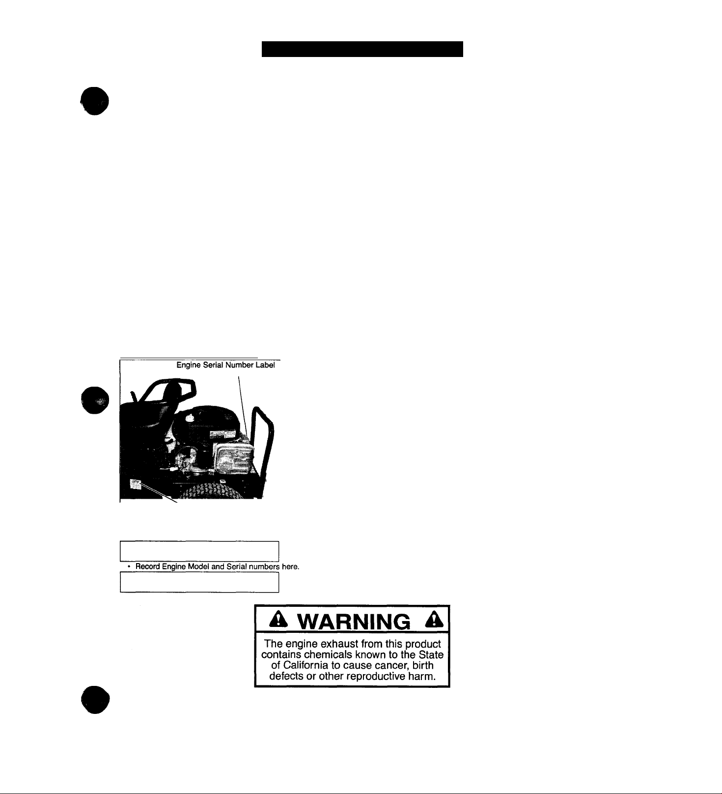
1.2 MODEL AND SERIAL NUMBERS
When ordering replacement parts or making service
inquiries, know the Model and Serial numbers of your
unit and engine.
Numbers are located on the product registration form in
the unit literature package. They are printed on a serial
number label, located on the frame of your unit.
1.3 PRODUCT REGISTRATION
The Ariens/Gravely dealer must register the product at
the time of purchase. Registering the product will help
the company process warranty claims or contact you
with the latest service information. All claims meeting
requirements during the limited warranty period will be
honored, whether or not the product registration card is
returned. Keep a proof of purchase if you do not
register your unit.
Customer Note: If the dealer does not register your
product, please fill out, sign, and return the product
registration card to Ariens/Gravely.
1.4 UNAUTHORIZED REPLACEMENT PARTS
Use only Ariens/Gravely replacement parts. The
replacement of any part on this unit with anything other
than an Ariens/Graveiy authorized replacement part
may adversely affect the performance, durability, and
safety of this unit and may void the warranty. Ariens/
Gravely disclaims liability for any claims or damages,
whether warranty, property damage, personal injury or
death arising out of the use of unauthorized
replacement parts.
Unit Serial Number Label
Figure 1 oaoo
Record Unit Model and Serial numbers here.
1.5 DISCLAIMER
Ariens/Gravely reserves the right to discontinue,
change, and improve its products at any time without
notice or obligation to the purchaser.
The descriptions and specifications contained in this
manual were in effect at printing. Equipment described
within this manual may be optional. Some illustrations
may not be applicable to your unit.
1 -3
Page 4

SECTION 2 - SAFETY
WARNING: This cutting machine is capable of
amputating hands and feet and throwing
objects. Failure to observe the safety
instructions in the manuals and on decals could
result in serious injury or death.
Slopes are a major factor related to loss-ofcontrol and tip-over accidents. Operation on all
slopes requires extra caution.
Tragic accidents can occur if the operator is not
alert to the presence of children. Never assume
that children will remain where you last saw
tf^m.
Gasoline is extremely flammable and the vapors
are explosive, handle with care.
Disengage attachment, stop unit and engine,
remove key, engage parking brake, and allow
moving parts to stop before leaving operator’s
position.
2.1 SAFETY ALERTS
These are safety alert symbols. They
mean:
A
A
•ATTENTION!
OL1253
•YOUR SAFETY IS INVOLVED!
When you see this symbol:
•BECOME ALERT!
•OBEYTHE MESSAGE!
2.2 SIGNAL WORDS
The safety alert symbols above and signal words below
are used on decals and in this manual.
Read and understand all safety messages.
DANGER: IMMINENTLY HAZARDOUS
SITUATION! If not avoided, WILL RESULT in
death or serious injury.
WARNING: POTENTIALLY HAZARDOUS
SITUATION! If not avoided, COULD RESULT in
death or serious injury.
CAUTION: POTENTIALLY HAZARDOUS
SITUATION! If not avoided, MAY RESULT in
minor or moderate injury. It may also be used to
alert against unsafe practices.
2.3 NOTATIONS
NOTE: General reference information for proper opera
tion and maintenance practices.
IMPORTANT: Specific procedures or information
required to prevent damage to unit or attachment.
2.4 SAFETY RULES
If unit is to be used by someone other than original
purchaser; loaned, rented or sold, ALWAYS provide
this manual and any needed safety training before
operation.
Read, understand, and follow all safety practices in
Owner/Operator Manual before assembling, using or
working on this mower.
ALWAYS remove key from ignition and wire from spark
plug before assembly, or working on this unit.
Inspect unit before each use for: missing or damaged
decals and shields, correctly operating safety interlock
system, and deterioration of grass catchers. Replace or
repair as needed.
ALWAYS check overhead and side clearances carefully
before operation. ALWAYS be aware of traffic when
crossing or operating along streets or curbs.
Keep children, people, and pets away. Be alert and
shut off unit if anyone enters work area. Keep children
under watchful care of a responsible adult.
NEVER allow children to operate or play on or near
unit.
Keep area of operation clear of all toys, and debris.
Thrown objects can cause injury.
Stay alert for hidden hazards, holes, and ruts.
Avoid uneven or rough terrain. DO NOT operate near
drop offs, ditches, or embankments. Unit can suddenly
turn over if a wheel is over the edge of a cliff or ditch, or
if an edge caves in.
Dust, fog, etc. can reduce vision and cause an
accident. Operate unit only when there is good visibility
and light.
Data indicates that operators, age 60 and above, are
involved in a larger percentage of riding mower related
injuries. These operators should evaluate their ability to
operate the riding mower safely enough to protect
themselves and others from serious injury.
Only trained adults may operate unit. Training includes
being familiar with controls and actual operation.
NEVER operate unit after or during the use of
medication, drugs or alcohol.
NEVER allow anyone to operate this unit when their
alertness or coordination is impaired.
2-4
Page 5

#
Wear adequate safety gear, sturdy shoes, and
protective gloves.
DO NOT wear loose clothing or jewelry and tie back
hair that may get caught in rotating parts.
Protect eyes, face and head from objects that may be
thrown from unit. Wear appropriate hearing protection.
Always wear safety goggles or safety glasses with side
shields when operating mower.
Avoid sharp edges. Sharp edges can cut. Moving parts
can cut off fingers or a hand.
ALWAYS keep hands and feet away from all rotating
parts during operation. Rotating parts can cut off body
parts.
ALWAYS keep hands away from all pinch points.
DO NOT touch unit parts which might be hot from
operafiin. Allow parts to cool before attempting to
maintain, adjust or service.
NEVER place your hands or any part of your body or
clothing inside or near any moving part while unit is
running.
NEVER direct discharge towards persons or property.
Thrown objects may ricochet back towards operator.
ALWAYS stand clear of the discharge area.
ALWAYS disengage attachment, stop unit and engine,
remove key, engage parking brake, and allow moving
parts to stop before leaving operator’s position.
Use extreme caution on gravel surfaces.
Disengage PTO when attachment is not in use and
when crossing gravel surfaces.
DO NOT operate unit if safety interlock system is
damaged or disabled. Check safety interlock before
each use.
ALWAYS remove key to prevent unauthorized use.
DO NOT operate at too fast a rate. Slow down before
turning.
Stop engine before removing grass catcher or
undogging chute.
DO NOT mow on wet grass. Reduced traction could
cfttjse sliding.
DO NOT try to stabilize the machine by putting your
foot,on the ground.
iOtow the weight of loads. Limit loads to those you can
saidy control and the unit can safely handle.
ALWAYS keep protective structures, guards and panels
¡n £K>od repair, in place and securely fastened.
Do r»t operate without either entire grass catcher or
ttie discharge guard in place.
DO NOT operate in reverse unless absolutely
necessary. ALWAYS look down and behind before and
while backing; especially for children.
Follow the manufacturer’s recommendations for wheel
weights or countenveights to improve stability when
using attachments.
NEVER carry passengers-especialiy children-even
with blades off.
Use extra care when approaching blind corners or
objects that may obscure vision of hidden obstacles
and children.
If you cannot back up a slope or you feel uneasy on it,
do not mow it.
Mow up and down slopes, not across them.
Use slow speed on any slope. Tires may lose traction
on slopes even though the brakes are functioning
properly.
Keep all movements on the slope s/ow and gradual.
DO NOT make sudden changes in speed or direction.
Use extra care while operating machines with grass
catcher or other attachments. They can affect stability
of the machine.
Avoid starting, stopping, or turning on a slope. If tires
lose traction, disengage the blades and proceed slowly
straight down the slope.
DO NOT operate on slopes over 10°.
DO NOT park on slopes unless necessary. If unit is
parked on a slope, ALWAYS chock or block wheels and
set parking brake.
DO NOT disengage or bypass transmission and coast
downhill.
Tow only with a machine that has a hitch designed for
towing. Do not attach towed equipment except at the
hitch point.
Follow the manufacturer’s recommendations for weight
limits for towed equipment and towing on slopes.
NEVER allow children or others in or on towed
equipment.
On slopes, the weight of the towed equipment may
cause loss of traction and loss of control.
Travel slowly and allow extra distance to stop.
Use extra care when loading or unloading unit onto
trailer or truck.
Secure unit chassis to transport vehicle. NEVER
secure from rods or linkages that could be damaged.
DO NOT transport machine while engine is running.
Keep unit free of grass clippings, leaves, and other
debris. Clean up oil or fuel spills.
This product is equipped with an internal combustion
type engine. DO NOT use unit on or near any
unimproved, forest-covered or brush covered land
unless exhaust system is equipped with a spark
arrester meeting applicable local, state or federal laws.
A spark arrester, if it is used, must be maintained in
effective working order by operator.
Fuel is highly flammable and its vapors are explosive.
Handle with care. Use an approved fuel container.
NO smoking, NO sparks, NO flames. ALWAYS allow
engine to cool before servicing.
2-5
Page 6

NEVER fill fuel tank when engine is running or hot from
operation.
NEVER fill or drain fuel tank indoors.
NEVER overfill fuel tank.
Replace fuel cap securely and clean up spilled fuel.
NEVER fill containers inside a vehicle or on a truck or
trailer bed with a plastic liner. Always place containers
on the ground away from your vehicle before filling.
When practical, remove gas-powered equipment from
the truck or trailer and refuel it on the ground. If this is
not possible, then refuel such equipment on a trailer
with a portable container, rather than from a gasoline
dispenser nozzle.
Keep the nozzle in contact with the rim of the fuel tank
or container opening at all times until fueling is
complete. Do not use a nozzle lock-open device.
If fuel is spilled on clothing, change clothing
immediately.
Avoid Electric Shock. Objects contacting both battery
terminals at the same time may result in injury and unit
damage. DO NOT reverse battery connections.
Explosive Gases from battery can cause death or
serious injury. Poisonous battery fluid contains sulfuric
acid and its contact with skin, eyes or clothing can
cause severe chemical burns.
NO flames, NO sparks, NO smoking near battery.
ALWAYS wear safety glasses and protective gear near
battery.
DO NOT TIP battery beyond a 45° angle in any
direction.
ALWAYS keep batteries out of reach of children.
Battery posts, terminals and related accessories
contain lead and lead compounds, chemicals known to
the State of California to cause cancer and
reproductive harm. Wash hands after handling.
Reverse connections may result in sparks which can
cause serious injury. Always connect positive (+) lead
of charger to positive (+) terminal, and negative (-) lead
to negative (-) terminal.
ALWAYS disconnect negative (-) cable FIRST and
positive (+) cable SECOND. ALWAYS connect positive
(+) cable FIRST, and negative (-) cable SECOND.
A frozen battery can explode and result in death or
serious injury. DO NOT charge or jump start a battery
containing frozen fluid. Thaw the battery before putting
on a charger or jump starting.
ALWAYS keep protective structures, guards, and
panels in good repair, in place and securely fastened.
NEVER modify or remove safety devices.
DO NOT change engine governor settings or over
speed engine.
Fumes from engine exhaust can cause injury or death.
DO NOT run engine in an enclosed area. Always
provide good ventilation.
ALWAYS maintain unit in safe operating condition.
Damaged or worn out muffier can cause fire or
explosion.
Stop and inspect equipment if you strike an object or if j
there is an unusual vibration. Repair, if necessary,
before restarting. Never make adjustments or repairs
with the engine running.
Mower blades are sharp and can cut you. Wrap the
blade(s) or wear gloves, and use extra caution when
servicing them. NEVER weld or straighten mower
blades.
Rotation of one blade may cause rotation of the other
blades.
Check brake operation frequently. Adjust and service
as required.
Keep all hardware properly tightened.
Stored energy in springs can cause injury.
Maintain or replace safety and instruction labels, as
necessary.
Never store the machine or fuel container inside a
building where there is an open flame, such as a watei|
heater.
Allow engine to cool completely before storing in
closed area or covering unit.
For extended storage, clean unit thoroughly. See
Engine Manual for proper storage.
Use only attachments or accessories designed for you|
unit.
Check attachment components frequently. If worn or
damaged, replace with manufacturer’s recommended]
parts.
2.5 SERVICE POSITION
CAUTION: Remove enough fuel so that no
spillage will occur. Remove battery to prevent
spillage of electrolyte.
WARNING: Always block wheels and know
that jack stands or blocks used are stable,
strong or secure and will hold the weight of
the unit during maintenance.
To ensure that unit is positioned in the proper service]
position:
1. Place jack stands under rear transaxle only.
2. If jacks are not available, place support blocks
under the transaxle at the rear of unit.
2-6
Page 7
2.6 CLEANING AND STORAGE
IMPORTANT: Never spray unit with water or store unit
outdoors to help prevent sealed bearing rust or
corrosion. Water can seep into sealed bearings and
reduce component life. Bearings are sealed against dirt
and debris only.
A unit that is excessively dirty should be cleaned before
work starts. Cleaning will occasionally uncover trouble
sources. Dirt and abrasive dust reduce the efficient
work life of parts and can lead to costly replacement.
When taking unit out of extended storage:
1. Check for any damage or loose parts. Repair,
replace or tighten hardware before operation.
2. If a preservative fluid was used in fuel tank, drain
aR(| discard. Fill fuel tank with fresh new fuel.
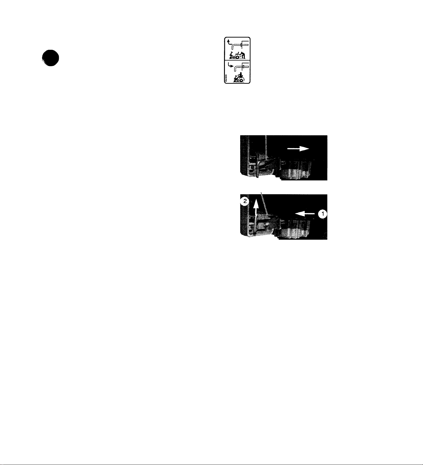
2.7 MOVING THE UNIT MANUALLY
WARNING: DO NOT disengage or bypass
transmission and coast downhill.
Disengage transmission
bypass lever to drive unit
and engage transmission
bypass lever to push unit
manually. Figure 3.
Figure 2
Transmission Bypass Lever Disengaged
to Drive Unit
Disengage transmission bypass lever to drive unit and
engage transmission bypass lever to push unit
manually (Figure 3).
Transmission Bypass Lever Engaged to
Drive Unit
Figure 3
2-7
Page 8

SECTION 3 - SPECIFICATIONS
Model Number 927061/927060 927063/927062
Description 102 8 123 2
Engine Manufacturer
Briggs & Stratton
927065/927064
144 0
Engine Power - hp (kW) @ governed RPM 10 (7 .46 ) 12( 8. 9) 14( 10 .4 ) :
Max Governed RPM 315 0 i
Fuei Tank Capacity - gai (L) 1.6 (6 .0 6) i
Starter Eiectric
Transrrtisfeion Hydrostatic i
Speed:Forward - mph (km/h) 5.5 (8 .8 5)
Reverse - mph (km/h)
2.5 (4 .0 2)
Power Take-Off Eiectric PTO Ciutch/Brake 1
Battery 12 Voit Maintenance Free 1
Parking Brake
Cutting Height - in. (cm)
Cutting width - in. (cm)
28 (7 1)
Internai Hydrostatic Transmission Brake |
1-1 /4 -4 (3 .18 -1 0 .2 ) 1
32 (8 1.3 )
40 (1 02 ) I
Max Tire Pressure:
Front - psi (kPa)
Rear - psi (kPa)
24 (1 65 )
12 (8 2.7 )
Tire Size.Front - in. (cm) 4 X 3. 5 X 10 4.1 0x 3. 5x 10
(10 .2 x8 .8 4x 25 .4 ) (10 .4 x8 .8 4x 25 .4 )
Rear - in. (cm)
8 X 6. 5 X 16
(20 .3 X 16 .5 x4 0. 6) (20 .3 X 16 .5 x4 0. 6) (20 .3 X 16 .5 x4 5. '!
8 X 6.5 X 16 8x6.5x1 8 1
4.1 0 X 3 .5 X 10 1
(10 .4 x8 .8 4x 25 .4
Turning Radius 12 (30 .5 ) 1
Weight — ibs (kg)
Height — in. (cm)
390 ( 17 7)
400 ( 18 1)
38. 7 ( 98 .4 ) 40( 10 2) 1
435 (1 97 ) j
Length — in. (cm) 66( 16 8) 67( 17 0) 1
Width — in. (cm) 3 3 (83 .8 ) 37 (94 ) 1
Max. Towing Capacity - ibs (kg) 100 ( 45 )
Max. Tongue Weight - ibs (kg)
30 (1 3.6 )
1
3-8
Page 9
SECTION 4 - GENERAL MAINTENANCE & ADJUSTMENTS
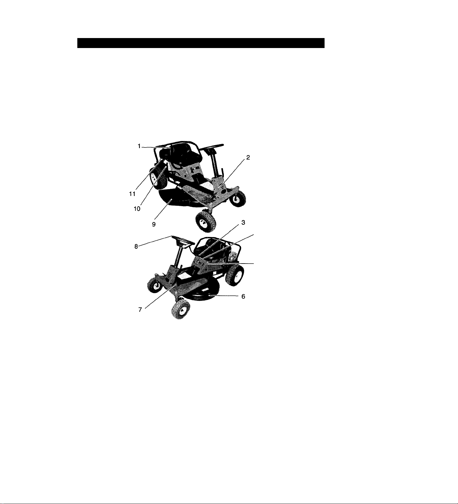
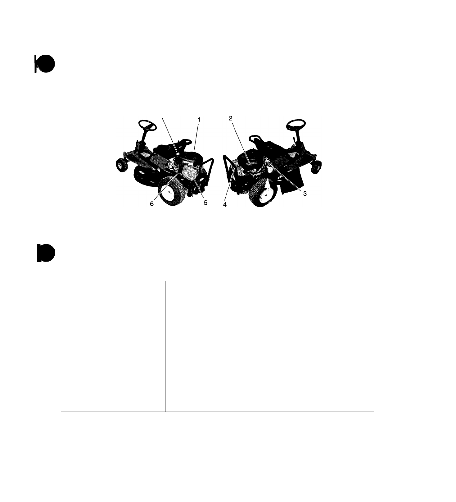
4.1 CONTROLS AND FEATURES
WARNING: AVOID INJURY. Read and
understand the entire Safety section before
proceeding.
1.
Seat
2. Forward and Reverse Pedal
3.
Throttle Lever
4.
PTO Switch
5. Ignition Switch
6. Mower Deck
7. Parking Brake
8. Steering Wheel
9. Discharge Chute
10.Mower Lift Lever
11 .Fuel Tank
Figure 4
4-9
Page 10

4.2 SAFETY INTERLOCK SYSTEM
4.3 FILLING FUEL TANK
WARNING: Safety interlock failure and
A
improper operation of unit can result in death
or serious injury. Check system before each
use to make sure it is functioning properly.
Perform the following tests to ensure safety interlock
system is working properly.
Test
1 Neutral Off
2 'i Forward
3
4
5
6*
7* Reverse Off
8*+
9*+
10*+ Neutral
‘Test with engine running.
+Operator lifts off seat.
Directional
Control
Pedal
Reverse Off
Neutral
Neutral Off
Forward Off
Neutral
Neutral Off
PTO
Off
On
On Disengaged
Off
Parking Brake Engine
Engaged
Engaged Doesn’t
Engaged Doesn’t
Engaged
Disengaged
Engaged
Engaged
Disengaged
Engaged
Starts
Start
Start
Doesn’t
Start
Doesn’t
Start
Shuts Off
Shuts Off
Shuts Off
Shuts Off
Runs
WARNING: EXPLOSIVE VAPORS and
FLAMMABLE FUEL can result in serious
injury or death. Handle fuel with care.
ALWAYS use an approved fuel container.
No Smoking!
No Lighted Materials!
No Open Flame!
Allow engine to cool.
Use caution with fuel. Fuel is very flammable.
Keep fuel in a clean and tight container. Keep
fuel away from fire or heat. Never put fuel in
the fuel tank while the engine is running or
hot. Clean up any spilled fuel before starting
the engine.
1. Clean fuel cap and surrounding area to prevent
dust, dirt, and debris from entering fuel tank.
2. Remove fuel cap.
IMPORTANT: See Engine Manual for correct type and|
grade of fuel.
3. Fill fuel tank to 1/2 in. (1.3 cm) below bottom of
filler neck. See Specifications for fuel tank capacity.J
4. Replace fuel cap.
4-10
Page 11
4.4 GENERAL LUBRICATION
WARNING: AVOID INJURY. Read and
understand the entire Safety section before
proceeding.
IMPORTANT: Proper maintenance can prolong life of
unit. The following chart shows recommended service
sdtedule. Refer to maintenance instructions in Engine
Manual for additional information.
NOTE: Use Figure 5 to locate items called out in main
tenance schedule.
1. Cooling System
2. Air Filter
3. Fuel Filter
4. Sparkplug
Interval Task
Each UseCheck Safety Interlock
System
Check Parking Brake
Clean Unit
Check Tires
Check Mower Blade(s)
Check Engine Oil
5. Muffler
Oil Drain Petcock
6.
7.
Oil Fill/Dipstick
Figure 5
Action
WARNING: Safety interlock system failure and improper operation
i of unit can result in death or serious injury. Test this system each
time unit is operated. If this system does not function as
described, do not operate until repairs are made.
Engage parking brake and engage transmission bypass lever (see Moving Unit
Manuaiiy). Push unit. If unit rolls, contact your Ariens/Gravely dealer.
Clean engine, battery, seat, mower deck, etc. of all dirt and debris. Do not use
solvents, hard cleaners, or abrasives.
Protect painted surfaces with automotive type wax.
See Specifications for correct tire pressure.
Check for worn or damaged blade(s) (see Sharpening Mower Biade).
Use oil fill/dipstick to check engine oil level. Add engine oil if needed, refer to
Engine Manual for detailed instructions.
»
4-11
Page 12

Interval
25 Hours
or Every
Season
Check Battery
Lubricate Unit
Action
Keep battery and battery terminals clean (see Cleaning Battery and Battery
Cables).
Apply grease to two front wheel zerks.
Zerk—
Clean air filter. Refer to Engine Manual for detailed instructions.
Drain engine oil by opening oil drain plug. Refer to Engine Manual for detailed
instructions.
Check mower blade mounting hardware and all other fasteners. Replace fasteners
that are missing or damaged. Tighten all nuts and bolts to correct torque value.
Replace muffler and spark arrestor (if equipped) if corroded. Contact your Ariens
Dealer.
Replace spark plug. Refer to Engine Manual for detailed instructions.
Replace fuel filter. Refer to Engine Manual for detailed instructions.
Clean cooling system. Refer to Engine Manual for detailed instructions.
Replace worn or deteriorated belts.
Check hydrostatic belt (see Hydrostatic Belt Replacement).
Check PTO belt (see PTO Belt Replacement).
Check mower belt (see Mower Belt Replacement (927064).
50 Hours
or Every;
Season
100
Hours or
Every
Season
Clean Air Filter^
Change Engine Oil^
Check Fasteners
Inspect Muffler and Spark
Arrestor
Replace Spark Plug
Replace Fuel Filter
Clean Cooling System^
Check All Belts
^ Service more often when operating under heavy ioads, high temperatures, or dusty conditions. Replace air filter
if very dirty.
^ Change after first 5 to 8 hours of use. Change every 25 hours when operating under heavy loads or in high
temperatures.
4.5 REMOVE AND INSTALL 28 AND 32INCH MOWER DECK
Remove (Figure 6)
1. Remove PTO belt.
2. Disconnect electric ciutch connector.
3. Disconnect guide arms from unit.
4. Disconnect two rear links and front guide from
mower deck.
5. Slide mower deck out from under unit.
Install
1. Slide mower deck under unit.
2. Instaii guide arms on unit.
3. Connect electric ciutch connector.
4. instaii PTO beit.
5. install front guide and rear links on mower deck.
4-12
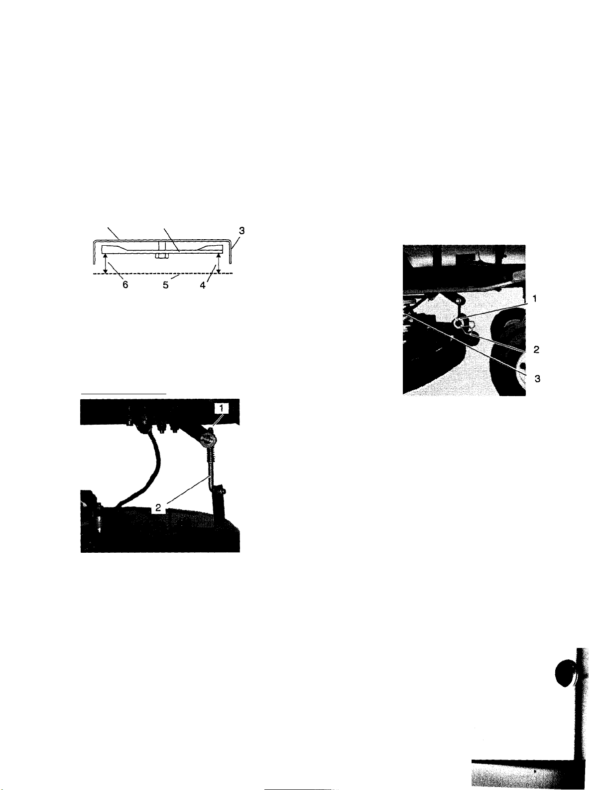
Page 13

ton a level surface, with tires inflated to correct
jre, and mower lift lever in the middle position.
|ure7)
ling height should be within 1/4 in. (6.35
I side of mower deck.
[mower blade(s) in line with discharge chute,
re distance from bottom of mower blade to
jnd.
Icertain the key is off and the spark plug wire
1 By hand rotate the measured blade to
ssite side of the deck.
1. Guide Arm
2. Rear Link
3. PTOBelt
4. Electric Clutch Connector
5. Mower Deck
6. Front Guide
Disconnect
Front Guide
Here
Figure 6
Adjust (Figure 8)
NOTE: Raise low side of mower deck half the mea
sured distance between low and high side of mower
deck. Lower high side of mower deck half the mea
sured distance between high and low side of mower
deck.
1. On low side: Turn trunnion nut clockwise several
turns.
2. On high side: Turn trunnion nut counterclockwise
several turns.
3. Check that mower deck is level.
ION: Use gloves or wrap a rag over the
sharp edges of the blade to prevent injury.
jre the distance of the same blade edge on
I new side (side opposite the discharge chute) of
»deck.
ver deck if needed.
Mower Deck Shown From The Front
2. 3
1. Discharge Chute 3. Mower Blade
Opening 4. Cutting Height
2. Mower Deck 5. Ground
Figure 7
1. Rear Guide
2. Trunnion Nut
Figure 8
4-13
Page 14
4.7 MOWER DECK PITCH ADJUSTMENT
Adjust on a level surface, with tires inflated to correct
air pressure, and mower lift lever in the middle position.
NOTE: The front blade cutting height should be 1/16 3/8 in. (1.59 - 9.53 mm) lower than the rear blade cut
ting height.
Check (Figure 9)
1. With the end of the mower blade(s) facing forward,
measure distance from bottom of mower blade(s)
to the ground at front of mower deck.
2. Turn mower blade(s) 180 degrees and measure
distance from bottom of mower blade(s) to the
ground at rear of mower deck.
3. Adjust mower deck if needed.
Mower Deck Shown From The Side
1 2
3. Check mower blade pitch.
• If mower blade pitch is not correct, go to step 4.
• If mower blade pitch is correct, the adjustment is
complete.
4. Check mower blade pitch.
5. Readjust as required.
4.8 REMOVE AND INSTALL 40-INCH MOWER DECK
Remove with the engine off and the mower deck raised
up, place support blocks under the frame of the mower
deck.
1. Lower the mower deck onto the support blocks
using the height adjustment lever. This will remove
tension on the linkage supporting the deck.
2. Unplug the electrical connector to the electric
clutch (Figure 11).
1. Mower Deck
2. Mower Blade(s)
3. Front of Mower Deck
Figure 9
Adjust Pitch (Figure 10)
1. Trunnion
2. Front Guide
4. Front Blade Cutting
Height
5. Ground
6. Rear Blade Cutting
i
1. Pin
2. Clip
3. Electrical Connector
Figure 11
3. Release the idler tension spring. Remove the
mower belt from engine pulley.
4. At the front support, pull one clip and remove the
pin from the link.
5. At the rear of the deck pull the bottom clip (Figure
12) and remove the washer before pulling out the
linkage. Repeat for the other support.
6. Slide the deck out from under the mower.
Figure 10
1. To raise front of mower deck; Turn trunnion
clockwise several turns.
2. To lower front of mower deck: Turn trunnion
counterclockwise several turns.
OA0034
M
4-14
Page 15

1. Deck Lift Rod
2. Trunnion
3. Bottom Clip
Figure 12
4.9 LEVELING THE 40-INCH MOWER DECK
Adjust on a level surface with tires inflated to the
correct air pressure. The lift lever should be in the
middle position.
NOTE: The cutting height should be within 1/4 inch
(6.35 mm) side to side on the same blade. Either blade
may be used. For convenience use the blade next to
the discharge chute.
1. With the key removed and the spark plug wire off,
rotate the blade by hand until one edge is at the
discharge opening.
2. On the high side: Remove bottom spring clip and
rotate the link rod counterclockwise (lengthen)
several turns. Reattach link rod to mower deck.
3. Check level.
4.11 MOWER HEIGHT ADJUSTMENT
1. Place deck lift handle in middle position. If mower
deck needs adjustment both the deck lift rod and
the link rods must be changed to maintain level.
2. Adjust the rear of the deck by pulling the pins on
the two trunnions and screwing the trunnion up or
down the link rod as needed.
3. The front is adjusted by removing the pin on the
rod pivot and screwing the pivot on the deck lift rod
as needed.
CAUTION: Use gloves or wrap a rag over the
sharp edges of the blade to prevent injury.
2. Measure the distance from the bottom of the blade
to the ground.
3. Rotate the blade half of a turn. This will place the
opposite end of the blade at the discharge chute.
The measured end of the blade will be at the
center of the mower deck.
4. Measure the distance of the same blade edge to
the ground.
5. Adjust mower deck if needed.
4.10 ADJUST LEVEL OF MOWER DECK
NOTE: Raise low side of mower deck half the mea-
'Hured distance between low and high side of mower
deck. Lower high side of mower deck half the mea-
»ired distance between high and low side of mower
deck.
1. On low side: Remove bottom spring dip (Figure
13) and rotate the link rod clockwise (shorten)
several turns. Reattach link rod to mower deck.
4-15
Page 16

4.12 ANTISCALP ROLLER ADJUSTMENT
IMPORTANT: Antiscalp rollers prevent lawn scalping.
DO NOT use antiscalp rollers to set cutting height.
Adjust all antiscalp rollers to same height.
NOTE: Adjust on a level surface, with tires inflated to
correct air pressure (see Specifications).
1. Select cutting height.
2. Adjust all antiscalp rollers to within 1/2 inch (1.27
cm) of ground (Figure 14).
1. Mower Deck
2. Antiscalp Roller
3. Pin
4. Mounting Hardware
4.14 FRONT WHEEL ALIGNMENT
Figure 14
4.13 TRANSMISSION NEUTRAL ADJUSTMENTS
1. Shut off engine.
2. Position rear wheels off the ground. Be careful to
secure the unit to the lift or position the unit to face
a wall for safety.
3. Engage seat switch and start the engine.
Disengage the parking brake. The drive wheels
should not be rotating. To adjust the neutral setting
for no wheel rotation:
4. Remove linkage to the shift arm. Test for wheel
rotation again as per #3 above.
5. If adjustment is necessary, loosen the two bolts on
the shift link. Figure 15.
6. The shift arm is spring returned to neutral. Adjust
the shift link until the wheels stop rotating. Tighten
the two bolts on the shift link.
7. Reattach the linkage to the shift arm.
1. Jam Nut
2. Tie-Rod
1. Measure the distance between jam nuts.
NOTE: The distance between jam nuts should be 7-5/8
to 7-3/4 in. (19.4 to 19.7 cm).
2. Adjust if needed (Figure 16).
3. Turn steering wheel to straight position.
4. Loosen the outer jam nut on the tie-rod that is to be
adjusted.
Disconnect the ball joint from the weldment.
5.
Screw the ball joint on the tie-rod to achieve the
6.
correct length.
7. Reattach ball joint to weldment.
8. Tighten jam nut against ball joint.
3. BallJoint
Figure 16
i
i
4
4-16
Page 17

4.15 REAR WHEEL AND HYDRO DRIVE
When the unit is turned off and the parking brake is
engaged, the unit should not roll, If the unit rolls, the
parking brake should be adjusted.
4.16 ADJUST PARKING BRAKE
1. Hair Pin
2. Clevis Pin
€
Figure 17
To Adjust Brake: (Figure 17)
1. Puli hair pin.
2. Remove clevis pin and lower the yoke.
3. Screw the yoke further onto the linkage rod.
4. Reattach the yoke and test the brake.
I
4-17
LJ
Page 18

SECTION 5 - ENGINE
5.1 ENGINE TROUBLESHOOTING
The following troubleshooting chart is to be used to
isolate engine problems and give possible causes and
corrective action responses.
The troubleshooting key is generic and can be used for
several types of engines. Use only those possible
causes and corrective actions that apply to the
unit.
TROUBLE
Black Exhaust
BlueA/Vhite Exhaust
Difficult Starting
Erratic Running
Excessive Fuel Consumption
Excessive Crankcase Pressure
High Oil Pressure
Knocking
Loss of Power or System
Low Cranking Power
Low Oil Pressure
Misfiring
Overheating 1, 19, 25,
Poor Compression
Starts and Stops
Vibration
Will Not Crank
Will Not Start
1,20, 22, 25, 29,31,32, 33 repair or replace
4, 20, 25, 31,33, 34 repair or replace
1, 5, 7, 8, 9,10, 20, 21,22, 29, 31, 32, 33
1, 7, 8, 9, 10, 20, 21,23, 26, 29, 33, 59, 62
1, 20, 22, 23, 25, 39, 31,32, 33 repair or replace
25, 31,33, 34, 45, 58 repair or replace
4, 41
22, 26, 29, 31, 33, 36, 46, 59 repair or replace
1, 8,10, 20, 21, 22, 23, 25, 26, 31,32, 33 repair or replace
2, 3, 4,11
3, 36, 37, 39
10, 20, 25, 26, 28, 29, 32
25, 28, 29, 31, 32, 33, 34,59,
1,6, 10, 62
20, 23, 25, 26, 29, 33, 45, 49
2, 11,45 charge battery or replace
1, 10, 62 repair or replace
POSSIBLE CAUSES
(Refer to Key Below)
CORRECTIVE ACTION
repair or replace
repair or replace
repair or replace
repair or replace
repair or replace
repair or replace
repair or replace
repair or replace
repair or replace
see electrical systems
see engine service manual
repair or replace
« i
see electrical systems
see engine service manual
TROUBLESHOOTING KEY
1
2
3
4
5
6
7
8
9
10
11
12
13
14
15
16
17
18
19
20
21
Restriction in air cleaner
Bad electrical connection
Faulty starter motor
Incorrect grade of lubricating oil
Low cranking speed 26
Fuel tank empty
Controls not in correct
operation position
Blocked fuel feed line
Faulty fuel lift pump
Choked fuel filter
Battery capacity low
Air in fuel system
Faulty fuel injection pump
Faulty fuel injectors or incorrect
type
Incorrect use of cold start
equipment
Faulty cold start equipment
Broken fuel injection pump
drive
Incorrect fuel pump timing
Incorrect valve timing
Poor compression
Blocked fuel tank vent
22 Incorrect grade of fuel 43 Faulty suction pipe
23
24
25
27 Cold running 48 Faulty engine mounting
28
29
30
31
32 Pitted valves and seats 53 Choked radiator
33
34 Worn valve stems and guides
35
36
37
38
39
40 Pressure relief valve sticking open 61
41
42
Sticking throttle/restricfed movement 44 Choked oil filter
Exhaust pipe restriction
Leaking cylinder head gasket 46 Incorrect piston height
Overheating 47 Damaged fan
Incorrect tappet adjustment 49 Incorrectly aligned flywheel and/or
Sticking valves 50 Faulty thermostat
Incorrect high pressure pipes 51 Restriction in water jacket
Worn cylinder bores 52 Loose fan belt
Broken, worn or sticking piston ring(s) 54
Restriction in air cleaner 56 Damaged valve stem oil deflector (if
Worn or damaged bearings
Insufficient oil in sump 58 Blocked sump strainer
Bad/defective oil temperature switch
Oil pump worn
Pressure relief valve sticking closed
Broken relief valve spring
45 Bad solenoid switch
flywheel housing
55 Choked breather pipe
57
59 Broken valve spring
60
62
Faulty water pump
fitted)
Coolant level too low
Exhaust or vacuum pipe leak
Bad or defective water temperature
switch
Bad spark plug(s)
5-18
Page 19

r
5.2 CHECKING ENGINE OIL
Check the engine oil daily prior to use.
IMPORTANT: Never operate the engine with the oil
below the low mark on the dipstick. See the engine
manual for oil specifications and oil filter service
instructions.
To check oil level:
1. Move the unit to level location.
2. Clean around the dipstick and filter tube to prevent
dirt from entering the engine.
3. Remove the dipstick and wipe off the oil on the
dipstick.
4. Put the dipstick back into the engine and tighten in
placp^and remove again.
5. When the dipstick is removed, note the oil level. Oil
should be between the full and add mark.
6. Replace dipstick.
7. If required, add 5W30 below 40° or 30W above
40°. Do not overfill.
8. Clean up any spillage that may have occurred.
5.3 CHANGING OIL
WARNING: DO NOT touch parts which are
hot. Allow parts to cool before servicing.
13. Check for leakage at the drain plug and oil filter if
used. Tighten the fittings as necessary if leakage
occurs.
14. Release the parking brake.
15. Return the unit into service.
5.4 CHECKING ENGINE COOLING
IMPORTANT: To prevent severe damage to the engine,
proper cooling will need to be maintained.
1. Check the air intake screen on the engine each
day.
2. The air intake screen must be kept clean. Remove
any grass, dirt, or debris that may have
accumulated.
3. Check the engine cooling yearly.
5.5 CLEANINGTHE AIR CLEANER
1. Check the air cleaner element every day.
2. Clean the air cleaner precleaner every 25 hours.
See your engine manual for instructions.
3. Apply oil and reinstall over the paper air filter
element.
4. Wipe out the air cleaner cover to remove any dirt
build up in the cover.
5. Reinstall the cover over the air cleaner prior to
operating the engine. See your Engine Manual.
Engine muffler and other parts will be hot if unit has
been running.
1. Engine oil should be changed after the first five
hours of operation and every 25 hours there after.
2. Move the unit to a level and well ventilated area
and set the parking brake.
3. If the engine is cold, let the unit run for five minutes.
4. When the engine is warm, stop the engine.
5. Clean the area around the dipstick and (drain
hose).
6. Put an open container that will hold at least one
gallon of oil under the drain hose.
7. Open the drain valve.
8. Allow the engine oil to drain completely into the
one gallon container. Remove container and
contents for future recycling as required.
9. Close the oil drain valve.
10.If used, remove the oil filter.
11 .Clean the oil filter port and install a new oil filter
according to the instructions on the oil filter. Fill
with new oil to the "full" mark on the dipstick.
12.Start and run the engine for one minute. Stop the
engine and recheck the oil level. Add oil as
necessary.
5.6 CHANGING THE AIR CLEANER ELEMENT
Replace the air cleaner element when clogged or every
100 hours. Do not attempt to clean. See your Engine
Manual for instructions.
5.7 INSPECT MUFFLER/SPARK ARRESTER
Inspect muffler and (if equipped) spark arrester.
Replace muffler if corroded, as it could create a fire
hazard and/or damage.
5.8 REPLACE SPARK PLUGS
Spark plug type and gap setting are shown in
Specifications. See Engine Manual for detailed
instructions.
5.9 ENGINE REMOVAL
1. Remove the hood from the units engine.
2. Remove the negative cable from the battery.
3. Remove the main drive belt from the engine
sheave by releasing the idler tension spring.
4. Remove the throttle and choke control from the
engine.
5-19
Page 20

5. Remove the electrical wiring from the engine
(charge lead, starter cable, fuel solenoid lead, and
magneto kill wire).
6. Remove fuel line from engine first. Drain fuel from
the line back into fuel tank.
7. Remove the engine bolts.
8. Lift engine out of the unit and off the frame with a
hoist (engine).
9. Service, overhaul, or replace engine as required.
10.If replacing engine with a new engine, the following
items will have to be removed (if used) from old
engine. These items will not be included with a new
engine: engine sheave and key, mounting
hardware, and engine wiring harness.
5.10 ENGINE INSTALLATION
1. Check the engine base and unit frame for damage
before installing the engine.
2. Piece the throttle and choke controls, fuel line, and
electrical wires out of the way prior to installing the
engine.
3. Once the engine is bolted onto the frame, tighten
the mounting hardware.
4. Install the engine sheave, belts, springs, eiectrical
wiring, throttle, and choke controls.
5. Install the negative battery cable onto the battery.
6. Install the fuel line.
I ^
7. Fill engine with 30W above 32°F (0°C) or 5W30
below 32°F (0°C).
Install the engine cover, then test operation and
8.
function of the engine.
WARNING: AVOID EXHAUST FUMES! DO
NOT run engine in an enclosed area.
ALWAYS provide good ventilation and wait
until hazard has been removed.
9. Check the fluid levels as follows:
Start the engine and allow it to reach to operating
temperature. DO NOT operate engine for more
than two minutes.
Shut the engine off, wait for engine to cool, and be
sure the engine oil level is between the full and add
marks on the dipstick, if it is below the add mark,
add recommended oil. DO NOT overfill.
i
5-20
i
Page 21

SECTION 6 - DRIVE TRAIN
c
6.1 HYDRO TRANSMISSION TROUBLESHOOTING
The following troubleshooting chart is to be used to
isolate hydro transmission problems and give possible
TROUBLE
Axles will not turn
Difficult starting
Erratic-ri^nning
Jerky when starting 1,4, 7, 8,12,18, 28, 38, 46
Jumps out of gear
Knocking
Loss of power or system
Noisy 4,12,18, 26, 28, 32, 37, 42
Oil leakage 4, 22, 51, 16
Operates hot 4, 16, 28, 32, 35, 42
Operates in one direction only
Pump failure 4,12, 37
Speed loss under load
Will not drive
Will not shift
1. 7, 8, 12, 16, 18, 28, 32, 38, 42, 46
1, 6, 7, 8, 12,16, 25, 26, 28, 38, 42, 46
1, 4, 6, 7, 8, 12, 18, 25, 26, 28, 42, 46, 55
N/A
4, 8,12,18,28, 37,42
4, 12, 18, 28,37, 42,46
1,8, 12,30, 46
1, 4, 6, 7, 11,12, 18, 26, 28, 37, 46, 51
1,7,8, 18, 28, 37, 38, 46, 48
cause and corrective action responses. The
troubleshooting key is generic and can be used for
several types of transmissions. Use only those possible
causes and corrective actions that apply to the unit.
POSSIBLE CAUSES
(Refer to Key Below)
1
2 Inspect acceleration valves
3
4
5 Low cranking speed
6 Controls not in correct
7
8
9
10
11 Improperly torqued attaching 32
12
13 Broken shifter stop 34
14 Inspect charge check valves
15 Inspect acceleration valves
16 Check oil level-gear box sump 37
17
18 Inspect bypass valve
19 Inspect charge pressure
20 Inspect inlet filter 41
21 Inspect charge relief valve
Inspect control linkage 22
Inspect charge check valves
Incorrect grade of lubricating oil 25 Bad transmission pump
operation position
Belts are missing, too tight,
ioose or giazed
Overload of vehicle 29 Check system pressure
Replacement parts damaged 30 Shift rod grooves worn 53
Replacement parts improperly
installed
screws
Air in hydraulic system
or reservoir
Inspect heat exchanger
TROUBLESHOOTING KEY
23 Inspect implement relief valve 44
24 Inspect charge pump 47
26 Overheating 49
27
28 Bad transmission motor
31 Reverse chain broken 54
33 Inspect auxiliary relief valve
35
36 Worn or damaged bearings
38 Inspect for loosely mounted
39 Steering column loose or binding
40
42
Inspect hoses and lines for wear
Cold running 50
Damaged cooling fan
Inspect cooling fan
Inspect transmission cooling fins
Metallic pieces or foreign objects in
unit
components
Pressure relief valve sticking open
Pressure relief sticking closed
Broken relief valve spring
43
48
51 Improper fit of case to cover
52 Dowel pins not installed
55 Worn or stripped gear teeth
Burrs on gearing
Gears improperly installed
Shifting washer in backwards
Shifter/Brake shaft keyways damaged
Unit clutch not disengaging
Shifter stop assembled backwards
Differential bevel gears broken
Spring in shifter weak or broken
6-21
Page 22

6.2 TRANSAXLE FLUID RECOMMENDATIONS
The fluids used in the transaxie has been carefully
selected, and only equivalent or better products should
be used.
Typically, an engine oil with a minimum rating of 55 sus
at 210°F and an API classification of SH/CD is
recommended. A 20W-50 engine oil has been selected
for use by the factory.
6.3 HYDROSTATIC BELT REPLACEMENT
Remove (Figure 18)
1. Remove PTO belt (see PTO Belt Replacement^.
CAUTION: Use care when releasing idler
spring tension. Keep body parts well away
from idler when performing this operation
2. Push idler towards the inside of the unit and
remove hydrostatic belt from idler.
3. Remove hydrostatic belt from engine sheave and
hydrostatic transmission pulley.
6.4 REMOVE TRANSMISSION
NOTE: Internal transmission repairs should only be
made by qualified personnel. This manual will describe
removing and replacing the transmission. Figure 19.
Other repairs should be made following the procedures
in the Peerless Manual.
1. Place unit on a flat surface and remove the
negative lead from the battery.
Remove key and spark plug wire.
2.
Remove mower deck.
3.
4.
Raise and block the units frame on jack stands
behind the transaxle on the frame.
Disconnect dump valve linkage by pulling the pin.
5.
Remove both wheels by removing snap ring.
6.
7.
Push idler for drive belt towards the inside of the
unit and remove drive belt.
8.
Remove tension spring and disconnect brake
linkage.
9.
Disconnect drive linkage ball joint.
lO.Unplug neutral switch located under the pulley.
11 .Unbolt front support.
12.Support drive unit and unbolt each side (by output
shafts).
13.Lower drive and remove.
NOTE: The brakes and direction linkage are installed
by Peerless. No adjustments should be needed. If the
neutral setting is not correct refer to Transmission Neu
tral Adjustments. For other repairs consult the Peerless
Manual.
1. Idler Spring
2. Engine Sheave
3. Hydrostatic Belt
4. Hydrostatic
Transmission Pulley
5. Idler
Figuréis
Install
1. Install hydrostatic belt on hydrostatic transmission
pulley and engine sheave.
2. Push idler towards the inside of the unit and place
hydrostatic belt on idler.
3. Slowly release idler until hydrostatic belt rests
firmly against idler.
4. Install PTO belt (see PTO Belt Replacement).
6.5 INSTALL TRANSMISSION
The drive unit is installed in the reverse order of
removal.
Check the linkages for brakes and direction for correct
length. Adjust as needed. The square keys for the
wheels should be replaced if they show any wear.
6-22
Page 23

t
1. Snap Ring 6. Neutral Switch Plugs
2. Dump Valve Rod 7. Front Support
3. Tension Spring
4. Brake Linkage Trunnion
5. Drive Linkage Ball Joint
Figure 19
8. Square Key
9. Yoke
6-23
Page 24

SECTION 7 - MOWER DECK
7.1 PTO BELT REPLACEMENT Remove
1. Lower mower deck to the ground.
CAUTION: Use care when releasing idler
spring tension. Keep body parts well away
from idler when performing this operation.
2. Pull idler towards the outside of the unit and
remove PTO belt from idler.
3. Remove PTO belt from mower deck pulley and
engine^heave.
Install
1. Install PTO belt on engine sheave and mower deck
pulley.
2. Pull idler towards the outside of the unit and place
PTO belt on idler.
3. Slowly release idler until PTO belt rests firmly
against idler.
7.2 MOWER BELT REPLACEMENT - 40INCH DECK (927064)
1. Right Pulley 5. Left Pulley
2. Idler 6. Clutch
3. Idler Spring
4. Mower Belt
7. Front Bracket
8. Clutch Bracket
9. Mower Deck
1. Idler Spring
2. Idler Pulley
Figure 20
Figure 21
Remove (Figure 21)
1. Remove mower deck (see Remove and Install 40
Inch Mower Deck).
CAUTION: Use care when releasing idler
A
spring tension. Keep body parts well away
from idler when performing this operation.
2. Remove idler spring.
3. Remove front bracket and clutch bracket.
4. Remove mower belt.
7-24
IP
Page 25

r
7.3 MOWER BLADE REPLACEMENT
CAUTION: Mower blades are sharp and can
cut you. Wrap the blades or wear gloves, and
use extra caution when servicing them.
28 And 32-inch Mower Decks (Figure 22)
Remove
1. Place mower lift lever in the highest position.
2. Block mower blade to prevent rotation.
3. Remove mower blade from clutch.
instaii
1. Install mower blade on clutch.
2. Torque hex bolts to 45-55 Ib-ft (61-75 Nm).
instaii
1. Install blade trays and mower blades on spindles.
2. Torque 3/4 in. jam nuts to 50-60 Ib-ft (68-81 Nm).
7.4 ELECTRIC CLUTCH - 28 AND 32-INCH MOWER DECKS
Remove (Figure 24)
1. Remove mower deck from unit.
2. Remove mower blade and debris shield.
3. Unbolt clutch from anti-rotation stop.
4. Remove bolt from center of spindle shaft. Clutch
should slide off the shaft.
Install
Clutch is installed in reverse order.
NOTE: Check keyways for burrs.
7.5 28 AND 32-INCH MOWER SPINDLE REPAIR
To remove the spindle bearings:
1. Remove mower deck from the unit.
2. Unscrew the bolt at the center of the top pulley.
3. Remove the pulley and key from the shaft. The
shaft with the clutch and blades should drop out of
the spindle housing.
4. Press out the bearings. Remove the spacer and
slinger from inside the spindle housing.
The bearing should be replaced, do not service.
Reinstall in reverse order.
40-inch Mower Deck (Figure 23)
NOTE: The 40-inch mower deck has two mower
blades.
Remove
2. Block mower blades to prevent rotation.
3. Remove mower blades and blade trays from
spindles.
7-25
Page 26

7.6 40-INCH MOWER SPINDLE REPAIR
To repair the blade spindles (Figure 25):
1. Remove the mower deck from the unit.
2. Remove spindle cover.
3. Remove drive belt from spindle sheave by
removing idler arm spring. The belt can be taken
off the sheave.
4. Unscrew nut from center of blade. Remove blade.
Pry off blade hub to remove. Remove woodruff key.
The spindle and sheave should push upward.
5. Remove the four bolts for the spindle housing.
6. Press out bearings.
The bearing should be replaced, do not service.
Install in reverse order.
7-26
Page 27

7-27
Page 28

7.7 40-INCH MOWER REPLACE THE ELECTRIC CLUTCH (FIGURE 25)
Remove
1. Remove the mower deck from the unit.
2. Remove drive belt by depressing the idler arm to
provide slack.
3. Unbolt the clutch bracket.
4. Unbolt clutch from anti-rotation stop.
5. Remove bolt from center of spindle shaft. The
clutch should pull off the spindle.
Install
Clutch is installed in reverse order.
NOTE: Check keyways for burrs.
7.8 40-INCH MOWER REPLACE CLUTCH SPINDLE BEARINGS
1. Remove the mower deck from the unit.
2. Remove drive belt by removing idler arm spring.
The clutch spindle has two bearings, one on each
side of the housing.
NOTE: Bearings are pressed in.
3. Unscrew the top bolt to remove the sheave and
key. The top bearing is accessible.
4. Unbolt housing from the mower deck to gain
access to the second bearing.
The bearings should be replaced, do not service.
Assemble in reverse order.
.
•i
7-28
Page 29

SECTION 8 - FUEL SYSTEM
8.1 FUEL SYSTEM TROUBLESHOOTING
The following troubleshooting chart is to be used to
isolate fuel system problems and give possible causes
The troubleshooting key is generic and can be used for
several types of transmissions. Use only those possible
causes and corrective actions that apply to the unit.
and corrective action responses.
TROUBLE
Hard starting
Fuel leak at carburetor 5,7, 1 7
Engine floods 5, 15, 17
Wi not idle 1,2, 3,6
Rich idle 1,6, 14
idles with needle closed 14
Hunts erratic idle
Idles fast lean
Will not accelerate 1, 6, 11, 12, 14, 15, 16
Over rich acceleration
Hesitates 2. 6, 11, 12, 16
Will not run at high speed 1, 1 1,12 ,14, 16
Low power
Hunts at high speed
Runs with needle closed 14
Engine overspeeds 2, 3, 7 ,14 repair or replace
1.3, 4, 6 ,11,1 2,14, 16,17 ,18
2, 3, 6, 7 ,12, 13, 1 4, 15 , 16 repair or replace
2, 3,7 repair or replace
1, 15 repair or replace
1,3, 11, 14, 1 5, 16 , 17, 18
3, 6, 7,1 2,14, 15,16 ,18
POSSIBLE CAUSES
(Refer to Key Below)
CORRECTIVE ACTION
clean, repair or replace
repair or replace
repair or replace
repair or replace
repair or replace
repair or replace
repair or replace
repair or replace
repair or replace
repair or replace
repair or replace
repair or replace
»
TROUBLESHOOTING KEY
1 Plugged air filter
2
3 Throttle or choke shaft worn
4
5
6
7
8
9 Stuck or dirty ball check
10
11
12
13 Idler port restricted
14
15
16 Main nozzle restricted
17
18 Fuel inlet plugged
Leaky carburetor gasket
Choke not functioning properly
Plugged atmospheric vent
Air bleed restricted
Damaged or leaky 0-rings
Damaged diaphragm
Diaphragm upside down
Plugged tank or vent
Fuel pickup restricted
Damaged adjustment needle and
seat
Incorrect float height
Dirty, stuck needle and seat
8.2 FUEL TANK REMOVAL
1. Remove seat and disconnect wires (Figure 26).
2. Remove rear hood if applicable.
3. Remove battery cover.
4. Loosen bolts to gas tank and remove top bracket.
WARNING: Gasoline is volatile. Keep away
from sparks and open flame. Gasoline fumes
will ignite.
5. Drain gas into the suitable container and dispose of
it properly.
6. Disconnect fuel hose.
7. Remove fuel tank.
8-29
Page 30

Any time fuel contamination is found in the fuel system
(dirt, water algae, etc.) replace the fuel, fuel filter and
flush the fuel lines. Remove the carburetor bowl and
clean. Replace all items that cannot be cleaned.
Reassemble the fuel system and check for proper
operation.
I
8-30
Page 31

SECTION 9 - FRONT SUSPENSION
9.1 STEERING
The steering, steering links, and spindle weldments
require only minor maintenance (Figure 27).
Check moving parts for wear and grease as needed.
Replace any bent parts and keep front wheels in
alignment. (See section Front Wheel Alignment)
9-31
Page 32

9.2 REPLACE STEERING PINION AND GEAR (FIGURE 27)
Remove
1. Remove steering wheel by punching out roll pin.
2. Slide tube and plugs off steering shaft.
3. Access the two roll pins that secure the pinion and
drive them out. The pinion should slide out of the
steering shaft.
4. Unbolt the steering gear from the linkage.
5. Remove the four bolts from the steering gear
bracket. Remove the assembly.
NOTE: The steering gear is stepped downward. It will
not function if installed upside down.
6. UnboMhe steering gear.
Install
1. Bolt the steering gear to the bracket. Observe top
and bottom placement.
2. The steering gear has thirteen roots or slots. Find
the center slot and mark it, Figure 28.
3.4.Find the primary tooth of the pinion and mark its’
location on the backside (bottom) of the circular
flange.
Insert the pinion shaft first, upward into the
steering gear. The primary tooth must position into
the center slot of the steering gear. Figure 30.
Primary tooth positioned
in center slot
The pinion is designed to have a tooth opposite a slot.
Secondly, the orientation of the roll pin holes is
perpendicular to one of the teeth (primary). Figure 29.
Figure 30
5.
The steering tube can be placed in position over
the shaft of the pinion. Be certain to hold pinion in
place with steering gear.
6.
The steering tube has two holes for roll pins. Use
one to hold position by placing a rod or punch
through it. The shafts can be rotated to allow the
first roll pin to be driven into position.
7.
Remove the locating rod and drive the second roll
pin into position.
8.
Slide the steering tube and plugs over the shaft
and position the steering wheel to align the roll pin
holes. Drive the steering wheel roll pin into
position.
Check assembly. With the steering wheel centered
rotationally the steering gear should have the hole
for the linkage centered fonward.
Attach the steering linkage to the steering gear.
I'f
Page 33

SECTION 10 - ELECTRICAL
10.1 TOOLS
There are some specialized tools and test equipment
that are needed for electrical repair work. A brief
description of these follows.
Long or needle nose pliers - used to connect or bend
wires and connectors in close quarters.
Diagonal cutters - used to cut wires or trim connec
tions.
Wire stripper/crimping tool - available separately or
as a combination tool. Used to strip insulation from
wif|^ of various sizes, crimp terminals and connector
or wires.
Soldering gun or soidering iron - used to solder all
splices and connections to terminals, connector, etc. A
soldering gun is faster and more convenient that wait
ing for a soldering iron to heat.
Multimeter - analog or digital, to measure voltage,
amperage and ohms.
Tachometer - used to measure engine speed.
Required to properly test alternator and charging cir
cuits where output is dependent upon engine speed.
Heat gun - used to shrink insulated tubing in place.
Used to replace electrical tape or insulated sleeving. To
use, place a piece of shrink tubing over a wire joint,
heat with the heat gun, until it shrinks slightly around
the joint.
Supplies - electrical tape, rosin core solder (never use
acid or acid core solder on electrical joints), an assort
ment of various size terminals, connectors, insulated or
heat shrink tubing (for use on joints and connections),
and an assortment of automotive type wire (in several
colors).
Ariens Company recommends that all work be done in
a professional manner. The use of the tubing to cover
joints and the soldering of connections contribute to a
professional looking job. In addition to a pleasing
appearance, repairs made in this manner are more
likely to withstand vibration. (The weakest points in an
electrical system are the joints where wires are
attached.)
Replace all defective components with Ariens/Gravely
replacement parts only. Engine parts, such as rectifiers
or alternator components should be secured through
the nearest engine service center.
Ariens Company does not recommend attempting to
repair electrical components. Most do not lend them
selves to repair and you would have more money
invested in "time of repair" than the part would cost and
the results may not be as good.
10.2 ELECTRICAL MEASUREMENTS
In many electrical circuits, there is some visible effect
which indicates that the circuit is functioning properly. A
switch is turned "ON" and a lamp lights. A key is
turned, a starter motor runs and cranks the engine.
If the lamp does not light, or the starter motor does not
run, some means of measuring voltage, current flow,
resistance and continuity is needed, (continuity means
there is a complete electrical path through the circuit or
component.)
To know exactly what conditions exist in an electrical
circuit requires AC and DC Voltmeter, AC and DC
Ammeter, and an Ohmmeter.
Multimeter
A single combination meter that does all of these things
is available. Such a meter is called a Multimeter or VoltOhm-multitester (VOM). Meters of this kind are avail
able in many forms and all change functions and
ranges with switches, or by plugging test leads into dif
ferent jacks. Multimeters are available in two basic
types. Analog and Digital.
Analog Meters
Analog Meters have a needle that moves across a
scale to give a reading. The longer the scale, the easier
it is to read and more accurate the reading will be. A
jeweled movement is used in this type of meter is more
likely to be damaged through rough handling (except
for overloaded Protected Meters) or by measuring high
values that exceed the range set on the meter than a
digital meter. They provide excellent service for the
money as long as they are used with care.
Digital Meters
Digital Meters do not have a movement and are there
fore more rugged. The reading shows up directly on a
display window of some type. Since they read direct,
no skill in reading the scale is required, nor is it neces
sary to set the range. The meter switches the ranges
automaticaily. One has only to select the function DC
Volts, AC Ampere, Ohms, etc.,) connect the test leads,
and the reading is shown on the display. Because of
the internal circuitry and the lack of a movement, these
meters are not likely to be damaged by overloads.
In the discussions that follow, either type of meter may
be used. Test procedures are the same. It is best to
learn proper procedures, even though some meters
may be more forgiving of mistakes. Where differences
in use may occur, they will be covered in the discus
sion.
10-33
Page 34

Voltage Measurement
There are two basic rules to be remembered when
using a voltmeter. A voltmeter measures the voltage
difference between the test leads and the voltmeter is
always connected across the circuit under test.
Current Measurement
The two rules to remember when measuring current
with an ammeter are; an ammeter measures the cur
rent that flows through the meter, and to measure cur
rent an ammeter must be connected into the circuit.
The latter rule means that the circuit must be opened,
and the ammeter wired into it. Because this procedure
is usually difficult, an ammeter is seldom used for trou
bleshooting.
WARNING: EXPLOSIVE GASES can result
in serious injury or death. ALWAYS keep open
flames, sparks, or smoking materials away
from battery.
POISONOUS BATTERY FLUID contains sul
furic acid and its contact with skin, eyes or
clothing can cause severe chemical burns.
ALWAYS wear safety glasses and protective
gear near battery.
DO NOT TIP any battery beyond 45 degree
angle in any direction.
ALWAYS KEEP BATTERIES OUT OF REACH
of children.
Resistat^e Measurement
An Ohmmeter is used to make resistance measure
ments and to check continuity through wires and elec
trical components.
There is one rule to keep in mind when using an ohm-
meter. The ohmmeter has a self contained battery and
requires no electrical power. Using the ohmmeter on a
circuit that has power applied may result in damage to
the meter.
IMPORTANT: Disconnect the equipment battery when
making Ohmmeter test or damage to the Ohmmeter
may result.
IMPORTANT: An ohmmeter reads the resistance of
whatever component is connected between the test
leads. It can be used to check wires, coils, light bulbs,
or any item that conducts current.
10.3 BATTERY
When charging battery, remove it from unit first. Keep
batteries out of reach of children. ALWAYS follow
information provided on battery by battery
manufacturer. Lead acid batteries generate explosive
gases. Severe chemical burns can result from improper
handling of battery electrolyte. Wear safety glasses and
proper protective gear when handling batteries to
prevent electrolyte from coming in contact with eyes,
skin or clothing.
WARNING: ELECTRIC SHOCK may result in
injury and/or damage to unit.
DO NOT allow tools or other objects to come
into contact with both terminal at the same
time. ALWAYS remove Negative (-) Cable first
to reduce risk of sparks when removing bat
tery. ALWAYS connect Positive (+) Cable first,
then connect Negative (-) Cable when install
ing battery.
WARNING: REVERSE CONNECTIONS may
result in sparks which may result in injury.
ALWAYS connect/disconnect cables in proper
order.
Battery Electrolyte First Aid
-External contact: Flush with water.
-Eyes: Flush with water for at least 15 minutes and get
medical attention immediately!
-Internal contact: Drink large quantities of water. Follow
with Milk of Magnesia, beaten egg or vegetable oil. Get
medical attention immediately!
IMPORTANT: In case of internal contact, DO NOT
induce vomiting!
Inspection, Cleaning, Drying, and Maintenance
Inspect the top of battery, terminals, cables, terminal
posts, and case for any accumulation of dirt, corrosion
cracks or loose or broken parts. Keep battery and its
terminals clean. Inspect monthly to maintain best
performance. Replace battery if damaged.
Remove hold down and bolt and lift battery out. Clean
or service battery away from unit. Remove corrosion
from battery terminals and cable connections with wire
brush, then wash with a weak baking soda solution.
Scrub the exterior of the battery and cable terminals
with a nonmetallic brush which has been dipped into a
mixture of baking soda and water.
After cleaning, apply a thin coat of grease or petroleum
jelly to terminals and cable ends to retard corrosion.
Reinstall battery.
Check the alternator voltage regulator output (if used)
at every periodic maintenance inspection. Over
charging is a common cause of battery failure.
Electrolyte Level
Every 25 hours of operation, check electrolyte level of
each cell by removing caps one at a time. The
electrolyte level should be at level indicated. Use
distilled water to fill each cell if needed. Install and
tighten each cap after checking.
at
10-34
Page 35

IMPORTANT: When distilled water is added to battery
during freezing weather, battery must be charged to
mix water with electrolyte, or water will remain at top
and freeze.
Battery Charger
Under normal conditions, the engine alternator will
have no problem keeping battery charged. When unit
has set for an extended period of time without
operation and the battery has been completely
discharged, a battery charger will be required for
recharging.
Before using a charger, an attempt can be made to
recharge the battery using the engine alternator by
jump starting the unit and allowing the engine to run.
Charging A New Battery
WARNING: FROZEN BATTERIES CAN
EXPLODE and result in death or serious
injury.
DO NOT charge a frozen battery. Let the
battery thaw out before putting on a charger.
IMPORTANT: DO NOT fast charge. Charging at a
higher rate will damage or destroy battery.
ALWAYS follow information provided on battery by
battery manufacturer. Contact battery manufacturer for
extensive instructions to charge battery.
2 \
3 //
________
_1
8. Connect positive (+) lead of charger to positive (+)
terminal, and negative (-) lead to negative (-)
terminal.
9. Charge the battery at two and a half amps for ten
hours or until all cells are gassing freely and the
specific gravity is constant over three 30 minute
intervals.
10.Immediately after charging, check the electrolyte
level. If low, add distilled water to bring cell up to
required level.
11 .Replace caps finger tight, wash off and dry battery.
12.Reinstall battery into unit and connect positive (+)
cable first, then negative (-) cable.
Specific Gravity Check
The specific gravity should be checked with a
hydrometer.
NOTE: The specific gravity should be checked in each
cell and should be the same for all cells. A variation in a
cell reading could be an indication of a problem. Sub
tract .004 from 1.265 for each 10°F below 80°F or add
.004 to 1.265 for each 10°F above 80°F.
A special temperature compensated hydrometer is
used to read the battery’s state of charge.
The reading on the hydrometer gauge should be above
1.225. If the reading falls below 1.225 specific gravity
there will be an insufficient charge.
ALWAYS charge the battery until the specific gravity of
1.265 is reached over 3 successive readings. Check
monthly to ensure charge is maintained. The
approximate state of charge can be determined by the
cell specific gravity of the rested open circuit voltage at
room temperature and the charging time can be
estimated. For example:
1. Positive terminal 3. Battery
2. Negative terminai
Figure 31 OF1670
1. Put unit into service position to gain access to
battery.
2. Disconnect negative (-) cable first, then positive (+)
cable.
3. Remove hold down and remove battery.
4. Place battery on bench or other well ventilated
place where electrolyte spill will not create
damage.
5. Remove caps and fill each cell to level indicated
with electrolyte at 1.230 ± specific gravity and 80
degrees F (27 degrees C).
6. Let battery stand for one half hour.
7. Check electrolyte level and add more if necessary.
OCV Specific
Gravity
12.60
12.4 1.225 75%
12.20
12.00
11.8 0
1.265
1.18 0 50%
1.13 0
1.10 0 0% 12 hours
%of
Charge
100%
25% 10 hours
If using an automatic tapering 12 volt charger, choosing
a good quality 5 to 10 amps 15VDC minimum output
charger and charge for 3 to 12 hours according to the
battery state of charge (see table above) or until the
specific gravity in each cell reaches 1.255 -1.265
specific gravity at 80 degrees F.
If using a constant current charger, charge at 1 to 2
amperes for the time given on the table above or until
full specific gravity is reached.
10-35
Charging
Time
...
3 hours
7 hours
Page 36

IMPORTANT: Charging at higher rates will damage the
battery and cause excessive gassing and acid
spewing.
Jump Starting
The unit used for jump starting should have a 12 volt
battery with at least 500 cold cranking amperes, and a
negatively grounded system.
1. Ensure battery is not frozen. If the fluid is frozen,
remove battery from unit and allow to thaw before
charging.
2.
Connect the positive (+) jumper cable to the
positive (+) terminal of the discharged battery.
Connect the other end of the same jumper cable to
3.
the positive (+) terminal of the booster battery.
4.
Connict one end of the second jumper cable to the
negative (-) terminal of the booster battery.
Make the final jumper cable connection to the
5.
engine block or the furthest ground point away
from the discharged battery.
WARNING: Make sure cables are clear of any
moving engine parts before starting engine.
6. Start engine (refer to Owner’s Manual). If engine
will not start after several tries, unit or battery may
need service.
7. After engine starts, leave cables connected for one
to two minutes.
8. Disconnect cables in reverse order.
9. Operate unit as normal to charge battery.
Storage
The battery is a perishable item and it should be stored
properly to obtain a long, useful life. Batteries not in
use will self discharge.
If the battery will not be used for more than three
months, it should be removed and stored in a cool, dry
place.
Any collection of dirt, grease, or electrolyte should be
removed from the top of the battery.
The battery must be recharged monthly or when the
cell specific gravity reads less than 1.255 specific
gravity. Before reinstalling the battery in the spring, it
should always be fully recharged.
10.4 SWITCHES
Switches either open a circuit to stop current flow or
close and allow current to flow through.
A normally open (N.O.) switch prevents current flow
until the switch is actuated, completing the circuit and
allowing current to flow through it. An example is a light
switch - the lights are off until the switch is actuated
and the lights go on.
A normally closed (N.C.) switch allows current to flow
until the switch is actuated, breaking the circuit and
stopping current flow through it. An example is an
ignition switch that grounds the magneto when in the
off position (completing the circuit) but opens the circuit
when in the ON position allowing the engine to operate.
Switches are selected with regard to Current rating
(contacts must be of sufficient size to carry the required
current). Voltage rating (switches insulated for specific
voltages). Case or housing (switches that are exposed
to moisture and must be sealed to prevent moisture
from entering), and Actuating type (push, puli, rotary,
momentary contact, or micro switches).
NOTE: Check that the connections to the switches are
secure and that a switch is being activated properly
before performing electrical test on switches. (Safety
switches on speed selector and clutch levers may be
out of adjustment and not activating.)
IMPORTANT: When checking switches, remove them
from their respective circuit by disconnecting the wires
from the switch at the connector(s). Damage could
result to the meter or machine components if switches
are left in.
Normally Open Switch
To test a normally open switch (key, headlight, safety,
or seat) connect the ohmmeter across the switch
terminals. Meter should indicate open circuit (infinite
resistance). Activate the switch. The ohmmeter should
read up scale to zero resistance (Close Circuit). This
indicates the switch is operating properly. Also check
from each terminal to the switch case (if case is metal),
reading should show infinite resistance indicating no
short to ground.
Variation from test results described indicates a
defective switch.
Normally Closed Switch
To test a normally closed switch connect the ohmmeter
across the switch terminals. Meter should indicate a
closed circuit (zero resistance). Activate the switch and
the meter should move to open circuit (infinite
resistance). Check from each terminal to ground
(switch case). Meter should show open circuit (infinite
resistance).
Variation from test results described indicates a
defective switch.
i
10-36
Page 37

Ignition Switch
NOTE: Refer to the wiring diagram of the unit involved
to determine switch functions and test using the meth
ods described.
The ignition switch incorporates a number of functions,
although not all functions are used on all equipment.
The switch has three positions: OFF, RUN, and a
momentary contact START position. Use an ohmmeter
to check the continuity of the switch in each position.
OFF Position - Should be continuity between contacts
G and M. These connections ground the engine
magneto and stop the engine in the OFF position.
RUN Position - Should be continuity between contacts
B and A. These connections supply power to the rest of
the wiring harness. Connections G and M open to each
other.
START Position - Hold switch in START position while
testing. There should be continuity between contacts
S1 and S2. These connections apply power to close
the solenoid contacts and operate the starter motor.
In addition to the above test, place the switch in the run
position and check between each contact and ground
(metal case) to be sure no terminals are grounded. If
the switch is operating properly, there will be no
continuity between contacts other that those described.
10.5 SOLENOID AND RELAYS
Solenoid and relays are both magnetically operated
devices. Both devices operate on the principle that
passing a current of electricity through a coil of wire will
create a magnetic field strong enough to attract a piece
of iron or steel. Each device uses this principle in a
slightly different manner.
Relay - A basic relay consists of a coil of wire wound
around a soft iron (magnetic) core. When current is
passed through the coil, the core is magnetized and
pulls down on a magnetic lever. The lever in turn is
attached to several switch contacts which open or
close other electrical circuits. In this fashion, a small
current can control one or more larger electrical
currents and actuate several other devices. In most
cases a relay contact moves only a fraction of an inch
and the magnetic pull is small.
Solenoid - A basic solenoid consists of a coii of wire
wound around a hollow tube. A magnetic core slides
inside the tube. When current is passed through the
coil, the core is pulled into the solenoid with
considerable force. With proper design, a solenoid can
exert considerable force over a distance of several
inched. A solenoid can therefore, pull a lever, close a
heavy contact, or perform other jobs that require a
straight line pull.
If a relay or solenoid fails to operate, the cause may be
either electrical or mechanical.
To check electrically, connect a voltmeter across the
coil of the device and activate the circuit that operates
the relay or solenoid. If the meter indicates no voltage
is applied, the cause is in the control circuit.
If the meter indicates proper voltage across the coil but
the device does not function, remove the power,
disconnect the wiring and check the continuity of the
coil with an ohmmeter. The meter should indicate
resistance, in the order of 3 to 5 ohms, if the coil is
intact. A high resistance indicates an open coil and a
defective device.
There are also a number of mechanical problems that
may cause the problem.
The starter solenoid in the Ariens/Gravely equipment is
a sealed unit used to actuate the starter motor on the
engines. These solenoids may have three or four
connections. The two large connections carry high
current to operate the starter motor. The small
connections are connected to the coil and carry the
control current.
To check the solenoid, disconnect the cables to the
starter motor, turn the ignition switch to the start
position, and listen for the solenoid to snap inside
contacts closed.
If no snap is heard, check across the coils with a
voltmeter. The voltage should read 12 volts with the
ignition switch in the start position. If no voltage
appears, the defect is in the start circuit.
If the voltage is correct, turn off the power and check
continuity of the coil with an ohmmeter. If the coil is
open, the solenoid is defective and must be replaced.
If the coil has the proper voltage applied, and the
continuity check indicates the coil is intact, the solenoid
plunger is stuck or the contacts are welded shut and
the solenoid must be replaced.
If the solenoid snaps shut, but the start does not
operate, check across the large contacts with an
ohmmeter. If there is no continuity when the solenoid
snaps shut, the contacts are defective and the solenoid
must be replaced.
10.6 FUSES
Fuses are connected in electrical circuits to protect the
circuits from damage due to overload or short circuits.
Fuses are a "weak link" in the circuit. They contain a
metal link designed to melt when a certain current
value is exceeded thus opening or disconnecting the
wiring. Once a fuse blows or melts it must be discarded
and replaced with a new fuse of the same value.
Since the function of the fuse is to protect the circuit,
NEVER attempt to defect the protective device by
bridging or replacing with a device of a higher current
rating.
Electrical testing of these devices is simple. Since the
device either conducts current (and is therefore
10-37
Page 38

functioning) or the device is open and is therefore
defective. Use an ohmmeter to check for continuity.
10.7 DIODES AND RECTIFIERS
Diodes are solid state, semiconductor devices. They
contain no moving parts and conduct current better in
one direction than the other. They are electrical "check
valves" and permit current flow in one direction, but not
in the other.
Diodes allow current to flow through one circuit without
"backing up" into another. In engine alternator circuits,
a diode is used to convert current which flows back and
forth (AC) in a circuit to current which flows only in one
direction (DC). A device which converts alternating
current to a direct current is called a RECTIFIER. A
diode is ope type of rectifier.
To check a diode, isolate if from the circuit by
disconnecting one end. With a multitester set on the
lowest ohms scale setting, measure the resistance in
one direction, reverse the test leads, and measure in
the other direction. Readings should be high in one
direction and low in the other. (If the readings are low in
both directions, the diode is shorted, and if the
readings are high, the diode is open.) If the readings
are the same in both directions, the diode is defective
and must be replaced.
IMPORTANT: Diodes are marked to indicate polarity (a
band on one end, an arrow on the side, or they fit on a
holder only one way.
i
.
w
Rectifiers
A battery is charged through the use of an alternator
located in or on the engine. A charging circuit contains
a rectifier because alternators produce alternating
current (AC) and batteries require direct current (DC)
for charging.
The rectifier may be built into the engine or it may be an
external part. It may also contain a regulator to prevent
overcharging the battery. (Servicing of rectifiers built
into the engine should be done by an approved engine
manufacturer’s service center. Such a service center
has access to the information and parts required to test
and repair or replace engine components, including
rectifiers and regulators.)
Units that contain both a rectifier and regulator are
tested in a working circuit to make sure the regulator
portion of the device is operating.
10-38
#
Page 39

10.8 CONTINUITY DIAGRAM
Model 927061, 063, 065
The diagrams below show the various states of connection for electrical components.
The solid lines on switches show continuity.
NOTE: All switches are viewed from the rear.
10-39
Page 40

10.9 ELECTRICAL SYSTEM
Model 927061,063,065
1. Clutch Switch
2. Diode
3. Switch
4. Key Switch
5. Light Switch (optional)
6. Light (optional)
7. 25 Amp Fuse
8. Relay
9. Solenoid
1 ©.Single Pole N.O. Switch
#{
10-40
Page 41

10.10 WIRING DIAGRAMS
Models 927061, 063, 065,060, 062, 064 - START
/ ^
TRANSMISSION
NEUTRAL
SWITCH
REAR PARKING
BRAKE SWITCH
10-41
Page 42

Models 927061,063, 065, 060, 062,064 - RUN PTO OFF
6
6
5
ENGINE
REGULATOR
MAGNETO KILL
1 1
3
4 4
5
WHITE / BLACK
______
r
I
HEADLIGHT
TRANSMISSION
NEUTRAL
SWITCH
BLACK
fi
STARTER
SOLENOID
■{IP
_Q] LT.BLUE qN^
POSITIVE
PATH FUSE
FUSE
25A
REAR PARKING
BRAKE SWITCH
i
10-42
Page 43

Models 927061,063, 065, 060, 062,064 - RUN PTO ON
TRANSMISSION
NEUTRAL
SWITCH
REAR PARKING
BRAKE SWITCH
A,
_____
FUSE
25A BLACK
,B
10-43
Page 44

Models 927061,063, 065, 060, 062, 064 - OFF
TRANSMISSION
NEUTRAL
SWITCH
REAR PARKING
BRAKE SWITCH
i
10-44
 Loading...