

Page 1
c^rtens
®
Series
Riding Mower
Parts
Manuai
PRINTED IN USA
PART NO. 027551C
8-95
Page 2

A Message to Ariens Parts Manual User
Your Ariens Dealer will be happy to supply any
service or advice which may be required to keep your
Ariens equipment operating at peak efficiency. He
stocks genuine Ariens parts and lubricants,
manufactured with the same precision and skill as the
original equipment. His factory trained staff is kept
well informed on the best methods of servicing Ariens
equipment and is ready and able to serve you. If
Introduction
The Information contained herein is intended for use
by Ariens Dealer’s trained servicemen and serves as
a supplement to and reminder of training sessions
conducted by Ariens Company. Before you attempt
any repair, adjustment or maintenance project, be
certain that you have read and fully understand the
instructions in your Owner’s and Repair Manuals.
Understand and follow each Danger, Warning,
Caution and all instructions exactly as given. Also be
sure that you have all tools, replacement parts and
other materials required to complete the project.
A network of Ariens Dealers and Distributors is
maintained in order to assure you of an adequate
supply of replacement parts and technical assistance.
Your local Ariens Dealer is required to order parts
through his distributor. When replacement parts are
required, use only genuine Ariens parts. Failure to do
so may result in product malfunction and possible
injury to operator and/or bystander.
engine repairs or service are required, they can be
obtained from an Ariens Dealer or from an authorized
engine manufacturer’s service center. If service is
required, be prepared to supply the service person
with the Model Number and Serial Number of the
equipment and engine, as well as a full description of
the problem encountered.
NOTE: All references to “Left”, “Right”, “Front” and
“Rear^’ are given from operator’s position.
NOTE: The descriptions and specifications
contained in this manual were in effect at the time the
manual was approved for printing. Ariens Company
reserves the right to discontinue models without
notice and without incurrying obligation. The
equipment described within this manual may not be
identified as either standard or optional and the
various illustrations may not all be applicable to your
particular unit. If you have questions, always check
with your Ariens Dealer.
NOTE TO ARIENS DEALERS: Refer to your current
Parts Price List for suggested parts stocking. Service
training for dealers is available at the Ariens Service
School. See your Ariens Distributor for the latest
school.
How to Order Replacement Parts
This Parts Manual is arranged for easy identification
of genuine Ariens Service parts that are illustrated
showing their relationship to one another. Item
numbers In the illustrations correspond to item
numbers in the first column of the parts list and are
followed by the Ariens Part Number, Description and
Quantity with variations between models and/or serial
numbers designated in the part description. S/N
000000> means this serial number and up with S/N
<000000 meaning up to this serial number.
Order parts from your nearest authorized Ariens
Dealer. For prompt service when ordering parts,
provide the following information.
1. MODEL AND SERIAL NUMBERS OF
EQUIPMENT
2. PART NUMBER (not Item Number).
3. DESCRIPTION
4. QUANTITY REQUIRED.
Page 3

Contents
Decals
.......................................................................
Electrical ...................................................................4
Frame and Seat
Steering.....................................................................8
Speed Selector .......................................................10
Brake and Clutch
Engine and Belts.....................................................14
Rear Axle
Gear Case...............................................................18
Mower Height Linkage
Mower Engagement Linkage
Mower Pan .............................................................24
Mower Spindle
This manual covers the models listed. Specific Model
and Serial Numbers of your unit and attachment are
on a label on the unit. Record these numbers in the
space provided and use them whenever parts or
service are required.
MODEL NUMBER
SERIAL number!
ENGINE NUMBER
SERIAL NUMBER
........................................................
....................................................
................................................................
............................................
..................................
........................................................
2
6
12
16
20
22
26
Models
Model 927037 (RM830e) - 8.5 HP
Briggs & Stratton w/30” Pan
Serial No. 006339 and up
Model 927043 (RM1230e) -12.5 HP
Briggs & Stratton w/30” Pan
Serial No. 001400 and up
Model 927045 (RM828e) - 8.0 HP
Briggs & Stratton w/28" Pan
Serial No. 000600 and up
Model 927047 (RM1132e) -11.5 HP
Briggs & Stratton w/32” Pan
Serial No. 000101 and up
Model 927048 (RM9028e) - 9.0 HP
Briggs & Stratton w/28” Mower
Serial No. 000101 and up
Model 927049 (RM9030e) - 9.0 HP
Briggs & Stratton w/30” Mower
Serial No. 000101 and up
Model 927050 (RM1232e) -12.0 HP
Briggs & Stratton w/32" Mower
Serial No. 000101 and up
Model 927301 (RM8028e) - 8.0 HP
Briggs & Stratton w/28” Mower
Serial No. 000101 and up
Model 927302 (RM1228e) -12.0 HP
Briggs & Stratton w/28” Mower
Serial No. 000101 and up
Model 927303 (RM1232e) -12.0 HP
Briggs & Stratton w/32” Mower
Serial No. 000101 and up
© Ariens Company - All Rights Reserved
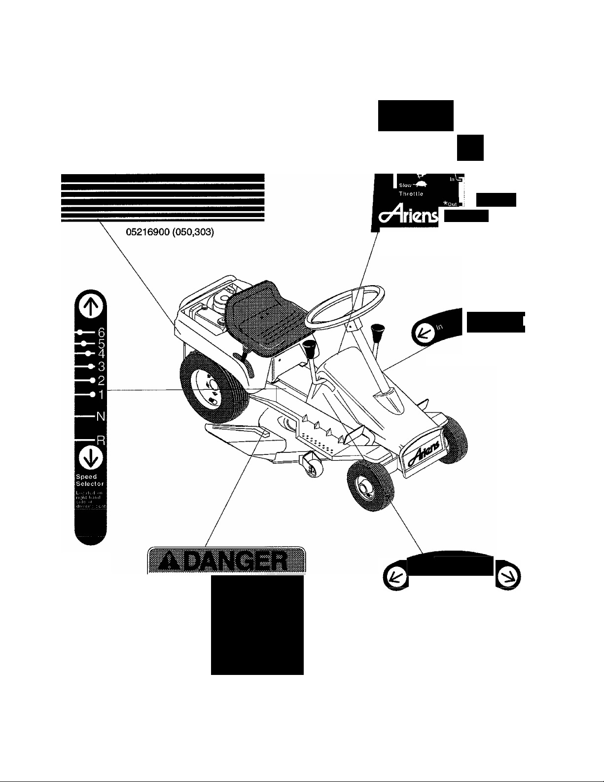
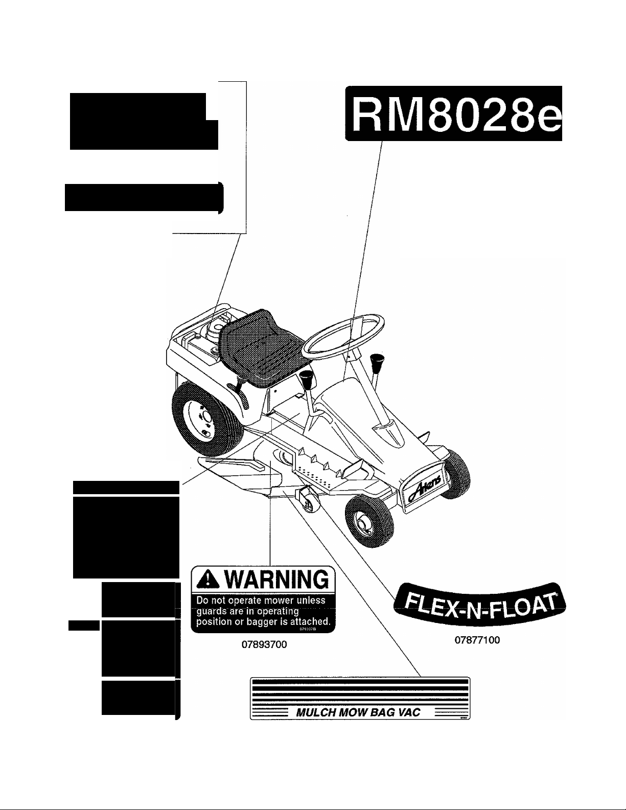
Page 4
||
lens
05216800 (050,303)
Decals
CAUTION
I Before sinning ongine he-
sure machine js in iicutrnl
and mower clutch is
« disengaged
V"'
few
Etigine
High Ignition
M ovjei' Mower
Clutch Height
02743000 Dash with Silkscreen
[\/lower
Clutch
07855200
ROTATING
BLADE
>Keep hands
& feet away.
>Stop engine &
remove ignition
key before
clearing.
07855500
Mower
Height
07855400
07798700 - (Not 927301,302,303)
07712100 - (927301,302,303)
Page 5
A CAUTION
Before starting engine be sure
machine is in neutral and
mower clutch is disengaged.
07855800
Cast Iron Bore
07797600
(Not 045,048,301)
Decals
07778600 07784700 07779400 077851000771070007785000 0771170007711800-
(927045,301)
(927037)
(927043)
(927050,303)
(927302)
(927047)
(927048)
(927049)
f AWARNINGÌ
TO AVOID SERIOUS INJURY
• RLiad opE?rator's manual. "!
• Undersiand localion and al i
• Look down and tiehind
■ Romoyc ohjccls fiatcou tiKoyifn
"by "the blade..............................................
• Avoid sttddon toms,
• Chock interlock system ix3i manual
• Keep all sheilds in place.
• Nevor carry chi Idem.
► Keep |5eople and pets away v;lien o|>= rating
»Go up and down tslopes, not across,
• ft machine stops going uphill, shut off
07859800 - (Not 301,302,303)
07712000 - (927301,302,303)
OR DEATH
funclion of all control^«. I |la|| ^
and while backing,
before uso.
machine.
PTO and back down slowly.
GO
• Release parking brake
• Depress clutch pedal
• Shill to 1st or 2nd speed
• Slowly lelcase clutch
» Shift to desired Sfjeed
STOP
» Depress clutch pedal
* DOiJress Brake ixidal
* Befoie leaving operator's
position:
Shift to neutral
Engage parking brake
Oi sen gage mower dutch
Stop Engjine
Remove ignition key
SERVICING
► Wait for all movement to slop
* Disconnect spark plug wire
• Before dpping unit, drain
gas larik arid remove
battery' i1 electric
07701700 (Not 037,043,049)
3
Page 6
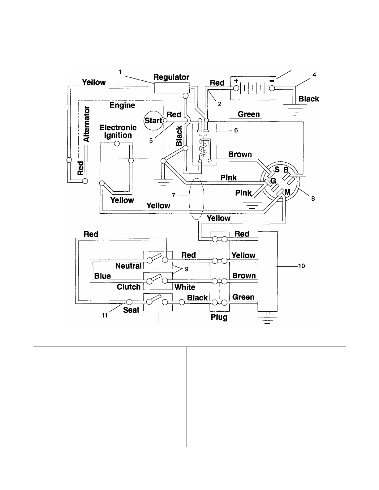
Electrical
Models 927037,043,045,047,048,049,050,301,302,303
ITEM
NO.
1
2
3
4
5
6
7
8
PART
NO.
01238500
02727900 Starter Cable 16”
02749400
02518900
02727200
03057700
02753600 Wire Harness RM
52707300
DESCRIPTION
Regulator
Battery
Ground Cable
Starter Cable 13”
Solenoid
B & S Engines
Switch Assembly
12
QTY.
ITEM
NO.
1
1
1 02754100 Switch-Snap Mounting N.O.
1
2
10
1
11
12
1
1
PART
NO.
9
02707800
02724000
02739700
03171600 Switch Seat 1
DESCRIPTION QTY.
Switch Interlock
(037,043,045,047)
(048,049,050,301,302,
303) 2
Module
Adapter - Seat Switch
2
1
1
Page 7

Notes
Page 8
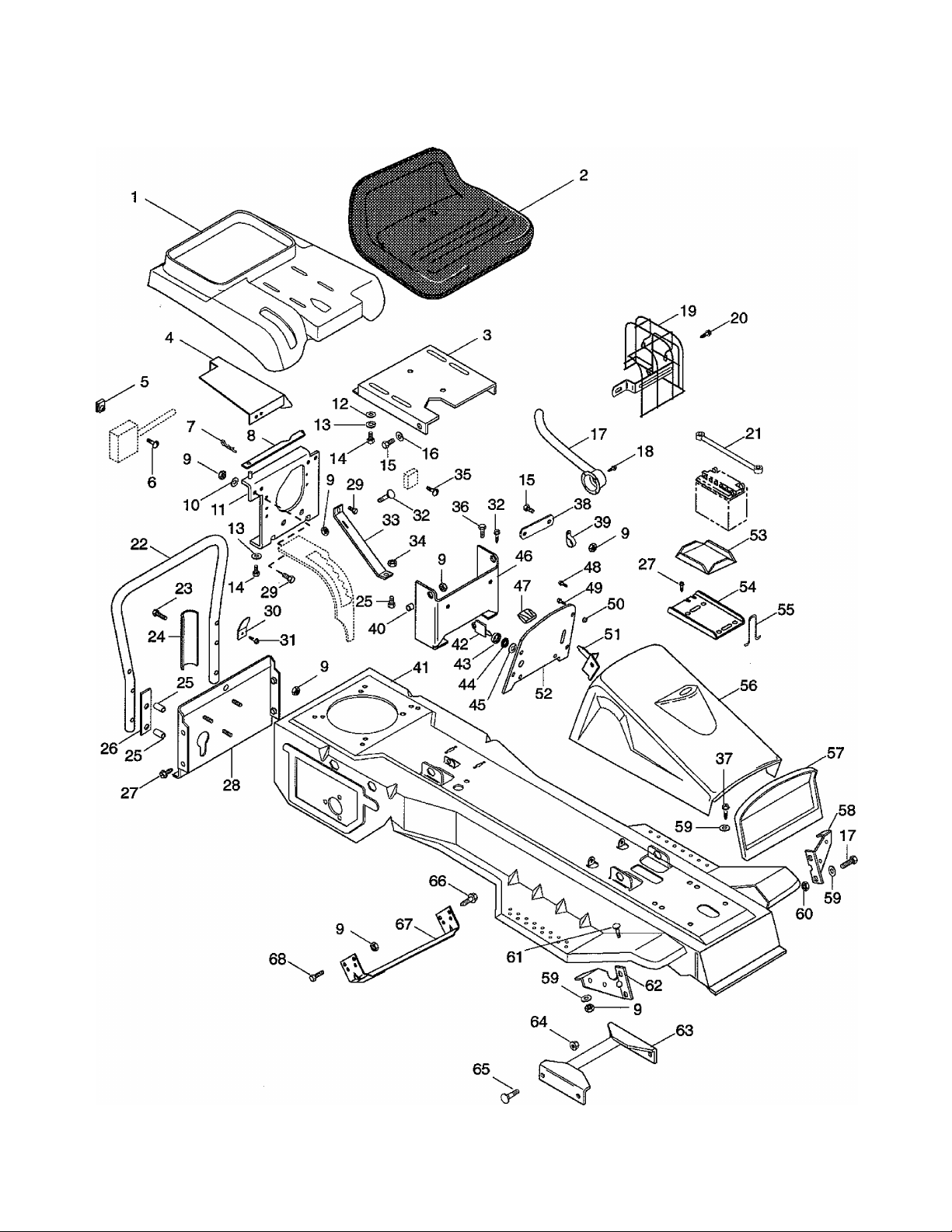
Frame and Seat
Models 927037,043,045,047,048,049,050,301,302,303
Page 9

Frame and Seat
Models 927037,043,045,047,048,049,050,301,302,303
ITEM
NO.
1
2
3
4
5
6
7
8
9
10
11
12
13
14
15
16
17
18
19
20
21
22
23
24
25
26
27
28
29
30
31
PART
NO.
02726400
03584600
03504100 Seat V-350 34 06504000
02743500
02735100 Baffle 1
06505100
06101400
06702000
02744900
06504200
06301800 Washer-Lock Internal .313 44 06517300 Nut-Panel .625-32 1
02739100
06400200
06300300 Washer-Lock .312 x .097 4 48 07406400
05913500
05902200
06407900
02729700
07403400 Screw-Tapping 8-32 x .38 4 54 02742300
02755500
02755600 Screw (302) 3 56 02708000
07507500 Battery Strap 1 57 02739500
02701200 StandupTube (043,045,048, 58 02718600
02726700 StandupTube (047,050,303) 1
05904500
05913000
02722700
01316600
02743900 Plate-Backing (047,050,303) 2 65 06203300
07401400
02701100
05902800
02726800
07404500 Screw-Tapping 12-24 x .50 68 05900200
Engine Cover (047,050,303) 1
Seat-V450 Neck .312-18 x.62
Screw-Machine 10-24 x .38 2
Pin-Hair Internal .08 x .18
Washer-Flat-Steel .38 x .875
Washer-Flat-Steel .344 x
Exhaust Pipe Assembly (047) 1
Bolt-Hex .31-18x1.50 (043,
Bolt-Hex .31-18x2.75
Screw-Tapping .312-18 x .50 2 Neck .31-18X.62
DESCRIPTION QTY.
(043,047,050,302,303) 1
(037,045,048,049,301) 1
Seat Bracket 1
Nut-Keps 10-24 2
X1.18 2
Seat Hold Down 1
Nut-Locking .312-18 16
X .030 2
Seat Leg Assembly 1
X .083 4
Bolt-Hex .31-18 X.75 4
Bolt-Hex .31-18 X.75 6
1.125X.063 2
Muffler Guard (302) 1
049,301,302) 1
045,048,049,301,302) 4
(047,050,303) 4
Service Bar Brace 2
Spacer (047,050,303) 4
Back Cover 1
Bolt-Hex .25-20 x .50 5 1.50
Clip (047,050,303) 2
(047,050,303) 2
ITEM
NO.
32 06202600
33 02700400
35 06101700
36 05903900
37 07405200
38 02538700
39 06907500 Clip (047) 1
40 01035800
41 52700200 Frame with Decals 1
42 02460900
43 07517700
45 06301900
46 02736400
47 07501900
49 07402600
50 07507600
51 06912700 Throttle Control 1
52 02743000
53
55 02515200
59 06405700
60 06509000
61 06201100
62 02718700
63 02705200
64
66 07402900
67 02717700
PART
NO.
02530700
06507800
DESCRIPTION QTY.
Bolt-Round Head Square
Brace
Nut-Locking-Center .250-20
Screw-Machine 10-24x .62
Bolt-Hex .31-18 X.50
Screw-Tapping .25-20 x .50
Strap (047)
Spacer Bushing
Key Set
Cap-Ignition Switch
Washer-Lock Internal .625
X.045
Seat Pivot Bracket
Knob
Screw-Tapping 10-12 x .50
Screw-Tapping 10-24 x .375
Plastic Grommet
Dash Panel - RM
Rubber Pad
Battery Tray
Hook
Cowl
Grille Insert & Shell Assembly
Left Hand Fender Brace
Washer-Flat-Steel .323 x
.625 x .062
Nut-Locking-Twin .312-18
Bolt-Round Head Square
Neck .31-18X.75
Right Hand Fender Brace
Frame Brace
Nut-Flange .312-18
Bolt-Round Head Square
Screw-Tapping .312-18 x
Frame Brace
Bolt-Hex .31-18X.63
1
1
2
2
4
4
1
2
1
1
2
1
1
6
2
6
1
1
1
2
1
1
1
4
2
2
1
1
4
4
1
1
3
Page 10

Page 11

steering
Models 927037,043,045,047,048,049,050,301,302,303
ITEM
NO.
1
2
3
4
5
6
7
8
9
10
11
12
13
14
15
16
17
18
19
20
21
22
23
24
25
26
27
28
29
PART
NO.
02753700 Steering Wheel 13 Inch 1 30
05803700
02749100 Steering Shaft 1
07503700
02753800 Tube 1
07401400
02707600 Brace 1 31
01212800
02707400
05801600
06201300 Bolt-Round Head Square
05505300
02705300 Steering Bracket 1 37
02506200 Spacer .380 x .750 x .236 1
06417400
06407500
06506000
06418100 Washer-Hardened-Steel-Thr 43
07402100
01310000
07409900
06512300
02506100 Steering Gear 1 47
02705400
07005300
06302100 Washer-Lock .375 x .094 4 51
06507800 Nut-Flange .312-18 4 52
06504600
02706600
DESCRIPTION QTY.
Pin-Roll .250x1.75
Plug
Screw-Tapping .312-18 x .50
Flange Bushing
Steering Support
Pin-Roll .188x1.00
Neck .38-16 X 1.0 1 35
Bushing-Flange .625 x 1.156
X.375
Washer-Flat-Steel .630 x
1.250 X.062
Washer-Flat-Steel .390 x
1.500 X.125
Nut-Locking-Jam-Center
.376-16
.515 X.97 X.062
Screw-Tapping 10-24 x .25
Retaining Plate
Screw-Tapping .312-18 x .50
Nut-Locking .375-24 2 46.
Pinion
Bolt-Serrated Round Head
Slotted .31-18X.75 4 50
Nut-Locking-Center .50-13
Axle Bracket
ITEM
NO.
1
1
11
5 32
1 33
2
34
36
1 X.072
38
1 39
40
1 41
1 42
1 44
4 .875 X .024
1 45
1 X .312 X .750
1 48
49
1 .812 x.065
1
PART
NO.
07126400 Tire/Wheel Assembly 2
07108000
01215200
05505800
07123100
01238200 Spindle Cup 2
00337700 Hub Cap 2
06700400
05516400
06700100
06405600
06404800
05905100 Bolt-Hex .50-13x4.00 1
05804000
02512000
02735300
02735400
02706300
02508600
06403800
05503700
06701400
02729200
02706400 Tie Rod
02917100 Ball Joint 2
06500500
02705800
06404300
DESCRIPTION QTY.
Tire 4.10/3.50-4
Zerk Fitting
Bushing-Flange .750 x 1.380
X .750 X 1.557
Wheel-Compression
Pin-Cotter .12 X 1.0
Bushing-Sleeve .500 x .750
X 1.560
Pin-Cotter .09 X .75
Washer-Flat-Steel .505 x .880
Washer-Flat-Steel .755 x
1.375 X .062 1
Pin-Groove .250 x 1.25
Spindle Washer
R.H. Wheel Spindle
L.H. Wheel Spindle
Arm
Hanger Pin
Washer-Flat-Steel .505 x
Bushing-Flange .500 x .625
Pin-Cotter .12 X 1.25
Axle
Nut .375-24
Steering Link
Washer-Flat-Steel .406 x
2
2
4
2
4
2
1
2
1
2
1
1
1
1
4
2
3
1
1
2
1
1
Page 12

Speed Selector
Models 927037,043,045,047,048,049,050,301,302,303
10
Page 13

Speed Selector
Models 927037,043,045,047,048,049,050,301,302,303
ITEM
NO.
1
2
3
4
5
6
7
8
g
10
11
12
13
14
15
16
17
18
19
20
21
22
23
24
25
26
27
28
29
30
31
32
PART
NO.
05921500 Bolt-Hex .31-18x1.50 1
07514500
02752400
02712900
06501500
05503600
02700700 Bell Crank 1
06420100
06407800
08309900
06700100
05902200
06407900
00607100
06504200
02700800 Shift Rod 1
06503100
03645500
01212900
05504700
05403900
02701700 Shift Link 1
06505400 Nut-Locking-Center .50-20 1
06418100 Washer-Hardened-Steel-Thr
02716100
52700900
06700400 Pin-Cotter .12 X 1.0 4
02701900 Transfer Shaft 1
02750900
07401400
02735200
07401700
DESCRIPTION QTY. ITEM
Knob
Shift Lever
Shoulder Bolt
Nut-Hex .312-18
Bushing-Range .372 x .500 36
X.312 X.625
Washer-Flat-Steel .531 x 38
1.250 X.100
Washer-Flat-Steel .38 x .626
X.033
Spring-Tension .92 x 69 x
1.75
Pin-Cotter .09 X .75
Bolt-Hex .31-18 X .75
Washer-Flat-Steel .344 x
1.125 X .063
Spacer Bushing .5 x .32 x .21
Nut-Locking .312-18
Nut .312-18
Ball Joint-Snap In
Flange Bushing
Bushing-Sleeve .625 x .750
X.500
Bearing Ball .625 x 1.375 Inside Diameter x .022
X .44
.515x .97X.062
Bearing Housing
Carrier Assembly
Carrier Yoke
Screw Tapping .312-18 x .50
Neutral Stop
Screw-Tapping .312-18 x .75
PART
NO.
33
1
34
1
1 X .61 1
35
3
1
37
39
1
40
1
41
42
1
43
3
44
1
45
2
1
46
47
3
48
49
1
1
50
2
51
2
52
53
1
54
55
56
57
1
58
1
59
1
60
61
1
5
62
1
63
4
NO.
05512800
05412000
07401900
06413400
02716000
02715900 Spindle Bolt 1
02528400 Disc
52704500
01212800
02703800 Shift Arm 1
06504300
02703900
06301800
06503200
06700300
06504000
06105000
02713400 Bracket Neutral Switch 1
02754200
06301100
06505500 Nut-Hex 10-24 1
06302600
06502600
07517300 Cable Tie 1
06510000 Nut-Jam .312-24 2
05915500
07405200
02707000
06203100
02704000
01035800
06405700
06908300 Clip 1
DESCRIPTION QTY.
Bushing-Sleeve .634 x 1.000
X .465
Bearing-Ball .750 x 1.781
Screw-Tapping .250-20 x .62
Washer-Hardened-Thrust
.758x1.23x.031
Disc Adapter
Drive Carrier Assembly
Flange Bushing
Nut-Locking-Center .312-24
Indicator Rod
Washer-Lock Internal .313 x
.030 6
Nut .250-20
Pin-Cotter .06 X .50
Nut-Locking-Center .250-20
Screw-Machine 10-24 x 1.00
Bracket-Neutral
Washer-Lock 10 x .047
Washer-Lock External #10
Nut 10-32
Bolt-Hex .25-20 x .50
Screw-Tapping .25-20 x .50
Quadrant
Bolt-Round Head Square
Neck .31-18x1.0
indicator
Spacer Bushing
Washer-Flat-Steel .323 x .625
X .062
1
4
1
1
1
1
2
1
1
2
1
4
1
1
1
1
1
6
2
1
1
1
1
1
11
Page 14

Brake and Clutch
Models 927037,043,045,047,048,049,050,301,302,303
12
Page 15

Brake and Clutch
Models 927037,043,045,047,048,049,050,301,302,308
ITEM
NO.
1
2 02505500
3
4
5
6
7
8
9
10
11
12
13
14
15 06301800
16
17
18
19
20
21 07005300
PART
NO.
02701300 Clutch, Shaft 1
06700400
06506200
02503300
06410400
02703500
06501500
06700100
06405700
02702700
06702400
02702800
06513800
08309000
02702200
02703700
08325200 Spring-Tension .051 x .60 x 39
02703600
DESCRIPTION
Flange Bushing
Pin-Cotter .12 X 1.0
Nut-Locking-Nylon .312-18
Brake Band
Washer-Flat-Steel .520 x
.81 Ox.033
Clutch Bracket
Nut-Hex .312-18
Pin-Cotter .09 X .75
Washer-Flat-Steel .323 x
.625 X .062
Brake Lever
Pin-Cotter .12 X .75
Clevis Pin .368/.373 x 3-1/4
Nut-Heavy .312-18
Washer-Lock Internal .313
X.030
Spring-Compression .105 x
.585 X .75 1
Brake Bracket
Brake Rod
2.25
Clutch Rod
Bolt-Serrated Round Head
Slotted .31-18X .75
QTY. ITEM
NO.
22
4 23
3
1 24
1 25
1 26
1 27
3 28
6
29
4 30
1 31
2 32
33
1
2 34
35
2 36
37
1 38
1
1 40
41
1
2
PART
NO.
06504200
06407900
01035800
08317900
05900200
02519400 Brake Latch
06400200
05900300
02703200
02713800
02740000 Clevis Pin .1847.186x1
06700300
02703300 Brake Arm
06504700
06106200
02519500
06506000
02703400
02706900 Pedal
06201000
DESCRIPTION QTY.
Nut-Locking .312-18
Washer-Flat-Steel .344 x
1.125 X.063 1
Spacer Bushing
Spring-Torsion .125 x 1.0 x
1.75
Bolt-Hex.31-18 X.63 1
Washer-Flat-Steel .38 x .875
X.083
Bolt-Hex .31-18 X 1.00 1
Clutch Pedal Arm
Clutch Arm
Pin-Cotter .06 x .50
Nut 8-32
Screw-Machine 8-32 x 1.00 1
Spacer Shoulder .344 x
.500 x .469 X .750 1
Nut-Locking-Jam-Center
.375-16
Brake Pedal Arm
Bolt-Round Head Square
Neck .38-16 X.75 2
2
1
1
1
1
1
1
2
2
1
2
2
1
2
13
Page 16

Engine and Belts
Models 927037,043,045,047,048,049,050,301,302,303
14
Page 17

Engine and Belts
Models 927037,043,045,047,048,049,050,301,302,303
ITEM
NO.
1 08231300 Engine - 8 HP B & S Elec
2 02755400
3 06512400 Nut-Locking-Top .312-18 4
4 02749600 Nipple 1 24
6
6
7 06409000 Washer-Flat-Steel .328 x 27
8 06602100 Key-Straight .25 x 2.0 x .25
9
10
PART
NO.
Order Engine and Parts from
Engine Manufacturers Dealer
08238600 Engine - 8.5 HP B & S l/C
08238700 Engine 11.5 B&S l/C (047) 1 16 07216900
08239800
08230600
08241200 Engine - 9 HP B & S 19
08241300 Engine - 9 HP B & S l/C
03563600 Pipe Cap 1 25
05914000 Bolt-Hex .31-18x1.50 4 26
02701000
07211200
DESCRIPTION QTY.
(045,301)
(037) 1 15
Engine-12 HP B&S l/C
Electric Start and Recoil
DC only Alternator 07215500 V-Belt 4L-Section 64-3/4 x
(050,302,303) 1
Engine-12.5 HP B&S l/C 17 06503900
Quiet (043) 1
Powerbuilt (048) 1 20
(049) 1 21
Pre-Guard-Rewind (301,302,
303) 1
.875 X .062 9
Engine Sheave
V-Belt 3L-Section 35-1/2 x
27/64 1
1 1.140X.250 1
1 28 02509200 Belt Finger Brace
1 29 06507800 Nut-Flange .312-18
ITEM
NO.
11 02755700 Guard (301) 1
12 07405400 Screw-Tapping 10-24 x .375
13 06408300 Washer-Flat-Steel .505 x
14 06300500 Washer-Lock .438 x .133 1
18 02714000 Shoulder Stud 1
22 06403800 Washer-Flat-Steel .505 x
23 06700100 Pin-Cotter .09 X .75 1
30 02504400
PART
NO.
05910300 Bolt-Hex .44-20 x 1.25 1
02700600 Idler Arm 1
06204800 Bolt-Round Head Square
00325400 Wave Washer 1
07321600 Idler-Flat 2.75 x .31
06504200 Nut-Locking .312-18 1
05902200 Bolt-Hex .31-18 X.75 1
08319200 Spring-Tension .062 x .72
DESCRIPTION QTY.
(301) 1
V-Belt HA 64.56 X.516
(037,043,045,048,049,
301,302) 1
17/32 (047,050,303) 1
Nut-Locking .375-16
Neck .31-18x1.25 1
.875 X .024 1
X6.65 1
Belt Finger
1
1
1
3
1
15
Page 18

Rear Axle
Models 927037,043,045,047,048,049,050,301,302,303
16
Page 19

Rear Axle
Models 927037,043,045,047,048,049,050,301,302,303
ITEM
NO.
1 00337700 Hub Cap 2 14 02718100
2 03516900 Spindle Cap 1 15 05800300 Pin-Roll .188x1.25
3 05511900 Bushing-Sleave .690 x .814 16 05409300
4
5 02209300 Spin Drive Zerk Fitting 1
6
7
8 05607100 Seal 1.125 X 2.496 X.38 1 07102100 Tire 8 X 6.50
9
10 01014200 Bearing Flange 1 07120900
11 06505600 Nut-Locking-Flange .250-20 3 07107700
12
13
PART
NO.
52704600
06302500
07401900
07402900
06403600
06700400
DESCRIPTION QTY. ITEM
NO.
X 1.000 2 17 00301700
LH. Axle Assembly 1 18 52700700 Gear Case Assembly
Washer-Lock .250 x .047 1 19 07115200 Tire/Wheel Assembly #35-16
Screw-Tapping .250-20 x .62 3 X 6.50-8 2
Screw-Tapping .312-18 x 07121000 Tire/Wheel Assembly 16 x
1.50
Washer-Flat-Steel .880 x 20 07406300 Screw-Tapping .500-20 x .62 8
1.380 X .062 1 21 01238200 Spindle Cup 1
Pin-Cotter .12 X 1.0 1 22 01036600 Push nut 1
2 6.5-8 2
PART
NO.
DESCRIPTION QTY.
Right Hand Axle 1
Bearing Ball .75 x .880 x .50
Bearing Flange 1
(See next page for detail) 1
Tire 16x6.50-8 2
Wheel Indus: #213435493 2
1
1
2
17
Page 20

Gear Case
Models 927037,043,045,047,048,049,050,301,302,303
26
18
Page 21

Gear Case
Models 927037,043,045,047,048,049,050,301,302,303
ITEM
NO.
1 02503400 Friction Disc Hub 1 15 02523400 Pinion Shaft
2 00300300 Friction Disc 1 16 05803400
3 02520600 Guard 1 17 02702300
4 06301900 Washer-Lock Internal 18 06403800
5 06507700 Nut-Locking Nylon .625-18 1 19 05409000 Bearing-Needle .50 x .688
6 05903900 Bolt-Hex .31-18 X.50 5 X.625
7 06301800 Washer-Lock Internal 20
8
9 52704200 Differential Assembly 2 22 02737100 Gasket 1
10 06600100 Key-Wood ruff .188 x .875 23 52700500
11 05605100 Seal .875x1.125x.125 1 25 00200900 Breather 1
12 06408900 Washer-Flat-Steel .627 x 26 05409100 Bearing-Ball 1.125 x 2.50
13 52700600 Service Gear Case 1 27 00015000 Multipurpose Grease 1
14 05403900 Bearing-Bail .625 x 1.375
PART
NO.
05511800
DESCRIPTION QTY. ITEM
NO.
.625 X .045 1 .875 X .024 2
.313X.030 5 .625 1
Bushing Sleeve .875 x 21
1.125x1.046 1 Assembly
X.38 1 24 07406600 Screw-Tapping 10-24 x 1.0 4
.990 X .032 1 X.63 1
X .44
2
PART
NO.
02737000
52502700
DESCRIPTION QTY.
Pin-Roll.125 X.75 1
Idler Shaft
Washer-Flat-Steel .505 x
Spacer-Cut .640 x .688 x
Pinion & Gear w/ Bearing
Gear Case Cover Assembly
1
1
2
1
1
19
Page 22

Mower Height Linkage
Models 927037,043,045,047,048,049,050,301,302,303
20
Page 23

Mower Height Linkage
Models 927037,043,045,047,048,049,050,301,302,303
ITEM
NO.
1
2
3
4
5
6
7
8
9
10
11
12
13
14
15
16
17
18
19
20
21
22
23
24
25
26
PART
NO.
05920900
06407900 Washer-Flat-Steel .344 x
00607100 Spacer Bushing .5 x .32 x
06506000
02720600 Rod Pivot
02728800
06504200
02729000 Rod-Rear Lift
06700200
01212800 Flange Bushing
02717600 Rear Mower Hanger
05900600
06201000 Bolt-Round Head Square
02719400
02722300 Adjustment Strap
06105000
06503900
06300400 Washer-Lock .375 x .155
05902300
02722200 Lift Strap
02519500
05906900 Bolt-Hex .31 -18x1.25
01035800 Spacer Bushing
06405700
05800300
05902200
DESCRIPTION QTY.
Screw-Socket Head .31-18
X.75
1.125X.063
.21
Nut-Locking-Jam-Center
.375-16
Link-Rear Lift
Nut-Locking .312-18
Pin-Cotter .09 X 1.0
Bolt-Hex .38-16x1.50 1 39
Neck .38-16 x.75 1
Positioning Arm
Screw-Machine 10-24 x 1.00
(037,043,045,047) 1 43
Nut-Locking .375-16
Bolt-Hex .38-16 x.75 1
Spacer-Shoulder .344 x .500
x .469 X .750
Washer-Flat-Steel .323 x
.625 X .062
Pin-Roll .188 X 1.25 1
Bolt-Hex .31 -18 X .75
ITEM
NO.
27
2 28
29
2 30
31
32
2
4 33
2 34
2
7 35
1 36
4
3 37
1 38
40
2
1 41
42
1 44
1 45
1 46
1 47
1
48
2
49
1
1
PART
NO.
02715600 Mower Lift Arm
02705100 Strap
06700100 Pin-Cotter .09 X .75
02728900 Link-Front Lift
06514800 Nut-Locking .375-16
06515500
02737800 Link-Front Lift
06418000 Washer-Flat-Steel .520 x
07514500 Knob
07408500
07400100 Screw-Tapping 10-12 x .50
02738800 Mower Height Lever
07401400 Screw-Tapping .312-18 x .50
07401500 Screw-Tapping .250-20 x .37
02754300 Reinforcement Stop
02719800 Stop (037,043,045,047)
06700500 Pin-Cotter .15 X 1.50
02712900 Shoulder Bolt
02748800
06301100 Washer-Lock 10 x .047
06505500 Nut-Hex 10-24 (037,043,
06701000 Pin-Hair Internal .08 x .38
02508600
02718800 Front Lift Arm (037,043,045,
02719700 Front Lift Arm
DESCRIPTION QTY.
Nut-Cupig Right Hand & Left
Hand Thread .37-16
.827 X .062
Screw-Tapping 12-14 x .50 3
(048,049,050,301,
302,303)
Quadrant
(037,043,045,047)
045,047)
xl.42
Hanger Pin
048,049,301,302)
(047,050,303)
1
1
2
1
1
1
1
4
1
3
1
2
2
1
1
1
1
1
1
1
1
2
1
1
1
21
Page 24

IVU...
Mower Engagement Linkage
Models 927037,043,045,047,048,049,050,301,302,303
22
57
Page 25

Mower Engagement Linkage
Models 927037,043,045,047,048,049,050,301,302,303
ITEM
NO.
1
2 06405700
3
4 00607100
5 06503900
6
7
8 08319100
9
10
11 06407900
12 06412300
13
14 05903400
15 02720400 Deck Pivot Bracket
16 01035800 Spacer Bushing
17 08301000
18 06702400
19
20
21 06501800
22
23 06517100
24 02751200
25 06502100
26 06300600
27 02719500
28
29 02709700
30
31
32 08309900
PART
NO.
06504200
00325400 Wave Washer (047,050,303)
02720600
06400200
02727100 Clutch Rod (047,050,303)
02721000
07401400
06700100
02751100 Clutch Rod Right Hand 51
06515500 Nut-Cupig Right Hand & Left 52
05900200
02507400
05904200
52706700 Clutch Rod Service Assembly
DESCRIPTION QTY.
Nut-Locking .312-18
Washer-Flat-Steel .323 x
.625 X .062
Spacer Bushing .5 x .32 x .21
Nut-Locking .375-16
Rod Pivot (047,050,303)
Washer-Flat-Steel .38 x
.875 X .083
Spring-Compression .148 x
.68 x 6.5 (047,050,303)
Arm (047,050,303)
Washer-Flat-Steel .344 x
1.125 X.063
Washer-Flat-Steel .344 x
.688 X .065
Screw-Tapping .312-18 x .50
Bolt-Hex .31-18 X .88
Spring-Tension .072 x .51 x
5.31
Pin-Cotter .12 X .75
Pin-Cotter .09 X .75
(047,050,303)
Nut-Hex .375-16
Hand Thread .37-16
(047,050,303)
Nut Left Hand Thread
.375-16(047,050,303) 1
Clutch Rod Left Hand
(047,050,303)
Nut .50-13
Washer-Lock .500 x .151
Front Anchor (047,050,303) 1
Bolt-Hex .31-18 X.63
Mower Adjustment Bracket 1
Cap Screw (037,043,045,
048,049,301,302)
Bolt-Hex .50-13x1.25
(047,050,303) 1
(047,050,303)
Spring-Tension .92 x 69 x
1.75
ITEM
NO.
11
33
34
35 07514500
1
1
36
1
37
1
38
1
39
40
2
41 07405200
1
1
42
1
43
2
44
1
45
3
2
46
47 01206300
1
48
1
1
49
1
3
50
1
1 301,302)
53 06801600
1
54
55
1
1
1
56
7
57
1
58
1
1
PART
NO.
02712900 Shoulder Bolt
02715700
02738900
02704400
01212800
02706800 Link
02705700 Clutch Link (037,043,045,
02719600 Clutch Link (047,050,303)
05801600
02716300 Adjustment Yoke (037,043,
06405800
02507200 Lock Spring (037,043,045,
07402100
06408200 Washer-Flat-Steel .328 x 1.0
02708800
02705500
02709400
02509400
02708900 Mower Brake Lever (037,043,
02709300 Clevis Pin .306/.311 X 3-1/2
02709200 Mower Engaging Arm (037,
02709100
52706500 Mower Brake Link Service
06701000
DESCRIPTION QTY.
Shaft
Knob
Mower Clutch Lever
Clutch Arm
Flange Bushing
048,049,301,302) 1
Screw-Tapping .25-20 x .50
Pin-Roll .188x1.00
045,048,049,301,302) 1
Washer-Flat-Steel .505 x
1.000 X .062
048,049,301,302) 1
Screw-Tapping 10-24 x .25 2
Blade Brake
X.094
Brake Bracket (037,043,045,
048,049,301,302)
Pivot Bracket (037,043,049)
Mower Engagement Link
(037,043,045,048,049,
Brake Clip (037,043,049)
Rivet .25 X .50 (037,043,045,
048,049,301,302) 1
045,048,049,301,302)
(037,043,045.048,049,
301,302)
043,045,048,049,301,302) 1
Mower Brake Link (037,043,
045,048,049,301,302)
Assembly (037,043,045,
048,049,301,302)
Pin-Hair Internal .08 x .38
Xl.42
1
1
1
1
1
1
1
1
2
1
1
1
1
1
1
1
1
1
1
1
1
1
23
Page 26

Mower Pan
Models 927037,043,045,047,048,049,050,301,302,303
24
Page 27

Mower Pan
Models 927037,043,045,047,048,049,050,301,302,303
ITEM PART DESCRIPTION QTY. ITEM PART DESCRIPTION QTY.
NO. NO. NO. NO.
1 06504000 Nut-Locking-Center .250-20 4
2 02709500 Hinge Plate 2
3 02202900 Bushing (037,043,049)
4 06511300 Nut-Wing .312-18 1
5 06409000 Washer-Flat-Steel .328 x .875 Assembly (032,043,049) 1
X.062 1 52706900 32” Mower Pan Head with
6 08307200
08318500 Spring-Tension .090 x .37 x
08314500
7 05706300 Ring-Retaining-Externa! .313 Neck .31-18X.62 7
8 03624200 Pin 1 20 06507800 Nut-Flange .312-18 4
9 02509700 Rear Mounting Bracket (037, 21
10
11 00212300 Clevis Pin 3/8 X 2 1 X.312 X.750
12 06701000
13 03708300 Swivel Bracket 1 25 02745400
14 02520400 Pan Head Chute Extension 302,303)
15 06201700 Bolt Round Head Square 30
16 06203700 Bolt Round Head Square 31 06503900
17 52706800 28” Mower Pan Head with 33 02736600 Adjusting Arm
07401400 Screw-Tapping .312-18 x .50
52707000 28” Deflector with Decals
53508200 32” Deflector with Decals 28 05913300
52706200 28” Mower Pan Head Service
Spring-Tension .095 x .50 x
1.0 (037,043,049) 1
.63 (048,301,302) 1 Assembly Retrofit (047,
Spring-Tension .090 x .37 x
.63 (047,050,303) 1 18 06203300 Bolt-Round Head Square
X.025 1 19
043,049) 2 22
Pin-Hair internal .08 x .38 x
1.42 1
(037,043,049) 1 26 07401600 Screw-Tapping .375-16 x .50 3
(045,048,301,302) 1
(047,050,303) 1 29 06500100 Nut-Jam .375-16
Neck .25-20 x .62
Neck .25-20x1.00 1 32 05904800 Bolt-Hex .38-16 X.88 1
Deflector & Decals 34 02736800 Front Bracket 30”
(045,048,301,302) 1
Assembly (045,048,301,
302) 1
1 (037,043,049) 1
4
23
24 02747600 Roller Clevis (045,047,048,
27 06201500 Bolt-Round Head Square
4 Neck .25-20 x .75 2
52702200 30” Mower Pan Head with
Deflector & Decals
52703400 30” Mower Pan Head
Deflector & Decals
(047,050,303) 1
52706100 32” Mower Pan Head
050,303) 1
06514900
06701600 Pin-Cotter .15-1.00 4
02747500 Clevis Pin .368 X .373 x 3.25 4
05503600 Bushing-Flange .372 x .500
06201200
Nut-Push .312
050,301,302,303) 4
Roller (045,047,048,050,301,
Neck .312-18x1.00 1
Bolt-Hex .38-16x1.25 1
Bolt-Round Head Square
Nut-Locking .375-16
(037,043,049) 1
2
8
4
1
1
1
25
Page 28

Mower Spindle
Models 927037,043,045,047,048,049,050,301,302,3032
26
Page 29

Mower Spindle
Models 927037,043,045,047,048,049,050,301,302,303
ITEM
NO.
1
2
3
4
5 06507800
6 01019900 Fastener (047,050,303)
7
8
g
10
11
12
13
14
15
16
17
18
19
20 02720700 Belt Finger (047,050,303)
21
22
23
24
25 02740400 Idler Arm (047,050,303) 1
26
PART
NO.
06501600
06300800
02719000
02750200 Mower Sheave (048,301,302) 1
02747800
01206100
02721100 Belt-Finger (047,050,303) 1 31
02740300 Brake Band (047,050,303) 1
08312000
06412300
06501500 Nut-Hex .312-18 2
06421200
06504200
06501800
06302100
06414500
07310900
06400200
01213200
01213100
06503900
05904500
05902700
06404300
06413000
06409300
DESCRIPTION QTY.
Nut-Jam .75-16
Washer-Lock .750 x .188
Mower Sheave (037,043,049)
Mower Sheave (047,050,303)
Mower Belt Finger (043,045,
048,049,301,302)
Nut-Flange .312-18
Spring-Compression .072 x
.687 X .75
Washer-Flat-Steel .344 x
.688 X .065
Washer-Flat-Steel .344 x
.688 X .75
Nut-Locking .312-18
Nut-Hex .375-16
Washer-Lock .375 x .094
Washer-Flat-Steel .390 x
.750 X.125
Idler 3.06 X .38 (047,050,303)
Washer-Flat-Steel .38 x
.875 X .083
Idler (047,050,303)
Bearing Spacer
(047,050,303)
Nut-Locking .375-16
Bolt-Hex .31-18x1.50
Bolt-Hex .38-16x1.75
Washer-Flat-Steel .406 x
.812 X.065
Washer-Flat-Steel .406 x
1,000x1.88
Washer-Flat-Steel .382 x
.812 X.062
ITEM
NO.
1 27
1 28
1 (047,050,303)
29
1
30
1 049,301,302)
2
1 32
1
33
34
1
1 35
1 36
1 37
1 38
39
40
1
1
3 41
1
1 42
2 301,302)
3
1
1
43
44
2
45
2
46
1
PART
NO.
02752900
05804800
06407300
02527600
05412000 Bearing Ball .750 x 1.78
02746700
00317200 Spindle Housing
05900400
03526700
02746800
06600300 Key Woodruff .188 x .75 2
05922900 Bolt-Hex .38-24 x 1.25 2
06518800 Nut-Jam .375-24 2
00341900 Bearing Slinger 1
06512200
00316900
02746900
00317000 Blade Tray (037,043,049) 1
02747100
02749300 28” Mower Blade (045,048,
02728700 Mower Blade 30 inches
02747000
05914500
06408300
06300500
05927700
DESCRIPTION QTY,
Pin (047,050,303)
Pin Roll .125 X .63
Washer-Flat-Steel .406 x
.865 X .094 2
Plate (037,043,045,048,
X.61 2
Spindle Housing (045,047,
048,050,301,302,303)
(037,043,049)
Bolt-Hex .38-16 X 1.00
Spindle Shaft (037,043,049)
Spindle Shaft (045,047,048,
050,301,302,303)
Nut-Locking Top .375-16
Retainer Hub (037,043,049) 1
Hub (045,047.048,050,301,
302,303)
Blade Tray Weldment (045,
047,048,050,301,302,303)
(037,043,049)
32” Blade (047,050,303)
Bolt-Hex .38-16x1.00
Washer-Flat-Steel .505 x
1.140 X.250
Washer-Lock .438 x .133
Bolt-Hex .50-13x4.50
1
1
1
1
1
6
1
1
2
1
1
1
1
1
2
1
1
1
27
Page 30

Ask your dealer for information about these other fine Ariens Products;
Front and Rear Tine Tillers
21" Walk-Behind Lawn Mowers
Walk-Behind Sno-Thros
Rear Engine Riding Mowers
Yard and Garden Tractors
Commercial Walk-Behind and Riding Mowers
m
aniens
Ariens Company
655 W. Ryan Street
© P.O. Box 157
Brillion, Wl 54110-0157
 Loading...