

Page 1

c Hr i en s O W NE R S M AN U AL
924000 SERIES
SNO-THROS
MODEL 924046 5 H.P. 24"
SMALL WHEEL
SERIAL NUMBER 000101 AND UP
MODEL 924048 7 H.P. 24"
SMALL WHEEL W/DIFFERENTIAL
SERIAL NUMBER 000101 AND UP
MODEL 9240S0 8 H.P. 24"
LARGE WHEEL W/DIFFERENTIAL
SERIAL NUMBER 000101 AND UP
MODEL 924052 10 H.P. 32"
LARGE WHEEL W/DIFFERENTIAL
SERIAL NUMBER 000101 AND UP
MODEL 924049
7 H.P. TRAC-TEAM TRACTOR
SMALL WHEEL W/DIFFERENTIAL
SERIAL NUMBER 000101 AND UP
MODEL 924081
8 H.P. TRAC-TEAM TRACTOR
LARGE WHEEL W/DIFFERENTIAL
SERIAL NUMBER 000101 AND UP
A mSA6i TO THE ARIENS CUSTOMER...
Welcome to the world of Ariens equipment. We are pleased
that you have selected Ariens and sincerely believe you have
purchased the best equipment available. The care you give
your new Ariens equipment will greatly determine the satis
faction and service life you will obtain from it. Use this manual
and the engine manual supplied, as your guide. By observing
the instructions and suggestions in these manuals, your Ariens
equipment will serve you well for many years.
Your Ariens dealer will be happy to supply any service or
advice which may be required to keep your Ariens equipment
operating at peak efficiency. He stocks genuine Ariens parts
and lubricants; manufactured with the same precision and
skill as the original equipment. His factory trained staff is
kept well informed on the best methods of servicing Ariens
ATTACHMENTS:
MODEL 824006 24" SNO-THRO
ATTACHMENT FOR SMALL WHEEL TRACTOR
SERIAL NUMBER 000101 AND UP
MODEL 824005 24" SNO-THRO
ATTACHMENT FOR LARGE WHEEL TRACTORS
SERIAL NUMBER 000101 AND UP
MODEL 824008 32" SNO-THRO
ATTACHMENT FOR LARGE WHEEL TRACTORS
SERIAL NUMBER 000101 AND UP
A SAFETY MESSAGE A
The product for which you have requested
information or repiacement parts is not a
current product. The replacement modeis
incorporate product designs, safety features,
safety instructions or warnings which repre
sent the latest “State Of The Art” develop
ments. For your safety and those around you
please contact your nearest Ariens/Gravely
Dealer for a demonstration of the current
product safety provisions and features.
equipment and is ready and able to serve you. If engine repairs
or services are required, they can be obtained from an Ariens
dealer or from an authorized engine manufacturer's service
station.
Should service be required on equipment, be prepared to
supply the serviceman with the Model Number and Serial
Number of the equipment and the engine, as well as a full
description of the trouble encountered.
Finally, your local Ariens dealer is in the best position to
answer your questions and service equipment. If for some
reason he is unable to satisfy your requirements, assistance is
aiways available from the Consumer Services, Ariens Company,
Brillion, Wisconsin 54110. Telephone: (414) 756-2141.
CT^riens
PART NUMBER 024449B
COMPANY BRILLION, WISCONSIN 54110
'A CUT ABOVE THE REST!
PRINTED IN U.S.A.
Page 2
SAFETY
INSTRUCTIONS
/VOID POTENTIAL HAZARDS
1. Read owners manual (or operating
and safely InstructionB
2. Observe alMabeisand Inatrucllont
3. Stop engine and wbH tor all movement
to atop before unclogglng or
servicing machine
4. Never allow children to operate the
equipment Never allow adults to
operate the equipment without proper
Inatruchon
5. Keep the area of operation clear of
all persons, especially children
6. Never direct discharge at bystanders
or allow anyone in front of unit
1 Keep machine properly maintained
and serviced with all shields, guards
and protective devices in place
78638
78617
78616
cT^riens
5 HP. 78640
7 HP. 78641
8 HP. 78642
10 HP. 78643
INSTRUCTIONS FOR SAFE OPERATION
A IMPORTANT
Safe Operation Practices for Snow Throwers
Training
1. Read the owner's manual carefully. Be thoroughly familiar
with the controls and the proper use of the equipment.
Know how to stop the unit and disengage the controls
quickly.
2. Never allow children to operate the equipment. Never allow
adults to operate the equipment without proper instruction.
3. Keep the area of operation clear of all persons, particularly
small children, and pets.
4. Exercise caution to avoid slipping or falling, especially
when operating in reverse.
Preparation
1. Thoroughly inspect the area where the equipment is to be
used and remove all doormats, sleds, boards, wires, and
other foreign objects.
2. Disengage all clutches and shift into neutral before starting
the engine (motor).
3. Do not operate the equipment without wearing adequate
winter outer garments. Wear footwear which will improve
footing on slippery surfaces.
ORDER ALL DECALS BY ARIENS PART NUMBER SHOWN
4. Handle fuel with care; it is highly flammable.
a. Use an approved fuel container.
b. Never add fuel to a running engine or hot engine.
c. Fill fuel tank outdoors with extreme care. Never fill fuel
tank indoors.
d. Replace gasoline cap securely and wipe up spilled fuel.
5. Use a grounded three-wire plug-in for all units with electric
drive motors or electric starting motors.
6. Adjust the collector housing height to clear gravel or
crushed rock surface.
7. Never attempt to make any adjustments while the engine
is running (except where specifically recommended by
manufacturer).
8. Let engine and machine adjust to outdoor temperatures
before starting to clear snow.
Operation
1. Do not put hands or feet near or under rotating parts. Keep
clear of the discharge opening at all times.
2. Exercise extreme caution when operating on or crossing
gravel drives, walks, or roads. Stay alert for hidden hazards
or traffic. Do not carry passengers.
3. After striking a foreign object, stop the engine, remove the
wire from the spark plug, thoroughly inspect the snow
thrower for any damage, and repair the damage before re
2 -
starting and operating the snow thrower.
Page 3
AWARNINGir^:;;;^^^
ROTATING PARTS
Stop engine and remove
spark plug ignition wire before
removing obstructions.
78618
(8,10 HP.[ 7 H.P. ENGINE DECAL 78637
5 H.P. ENGINE DECAL 78611
8 H.P. ENGINE DECAL 78636
10 H.P. ENGINE DECAL 78635
78645
WUfmllll
ROTATING PARTS
Keep clear of collector
rakes while engine
is running
78644 (ON LEFT
78345
WHEEL HUB OF
MODELS 924048,
924050 & 924052)
BE AWARE OF SAFETY DECALS
4. If the unit should start to vibrate abnormally, stop the
engine and check immediately for the cause. Vibration
is generally a warning of trouble.
5. Stop the engine whenever you leave the operating position,
before unclogging the collector/impeller housing or dis
charge guide, and when making any repairs, adjustments, or
inspections.
6. When clearing, repairing, or inspecting, make certain the
collector/impeller and all moving parts have stopped. Dis
connect the spark plug wire.
7. Do not run the engine indoors, except when starting the
engine and for transporting the snow thrower in or out of
the building. Open the outside doors: exhaust fumes are
dangerous.
8. Do not clear snow across the face of slopes. Exercise ex
treme caution when changing direction on slopes. Do not
attempt to clear steep slopes.
9. Never operate the snow thrower without proper guards,
plates, or other safety protective devices in place.
10. Never operate the snow thrower near glass enclosures, auto
mobiles, vyindow wells, drop-offs, etc, without proper ad
justment of the snow discharge angle. Keep children and
pets away.
11. Do not overload the machine capacity by attempting to
clear snow at too fast a rate.
This engine
has provisions
for electric
starter kit.
78607
®|iTecumseh Engine
instructions
CAUTION
i^or your personal protecfinn.
““read all safety notes in engine
own«T s manual
OPERATION
F-or detailed lubru alion start
inq A operating instriu.('ons,
see (‘ngme owner s manual 4
equipment mtr s insfrut ttons
LUBRICATION
Summer SAE 10 Oil
78608
Winter SAt SW 30 0.1
Te< umseh Prectiu Is ( ompany
son Ni'rt.i
r-aften wi S,l0/'4 USA
78609
ORDER ALL DECALS BY ARIENS PART NUMBERS SHOWN
12. Never operate the machine at high transport speeds on
slippery surfaces. Use care when backing.
13. Never direct discharge at bystanders or allow anyone in
front of the unit.
14. Disengage power to the collector/impeller when snow
thrower is transported or not in use.
15. Use only attachments and accessories approved by the
manufacturer of snow thrower (such as wheel weights,
counterweights, cabs, etc).
16. Never operate the snow thrower without good visibility or
light. Always be sure of your footing, and keep a firm hold
on the handles. Walk; never run.
Maintenance and Storage
1. Check shear bolts, engine mounting bolts, etc, at frequent
intervals for proper tightness to be sure the equipment is in
safe working condition.
2. Never store the machine with fuel in the fuel tank inside a
building where open flame or sparks are present. Allow the
engine to cool before storing in any enclosure.
3. Always refer to owner's manual instructions for important
details if the snow thrower is to be stored for an ex
tended period.
4. Run the machine a few minutes after throwing snow to
• 3 -
prevent freeze-up of the collector/impeller.
Page 4
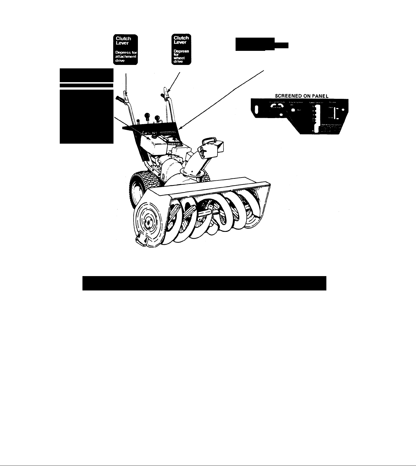
CONTROLS
SPEED SELECTOR: Sets speed of tractor. Change
©
speed or shift to reverse.
THROTTLE: Controls engine speed. On 5 and 7 HP
Models move throttle control to "FAST" position
after engine has stopped to minimize throttle damage
due to freezing. On 8 and 10 HP Models move
©
throttle to "SLOW" position after engine has stopped
to minimize throttle damage due to freezing.
WHEEL DRIVE CLUTCH LEVER: Activates tractor
drive. Depress to move tractor, release to disengage
©
drive and stop machine.
ATTACHMENT DRIVE CLUTCH LEVER: Activates
auger and impeller. Depress to run auger and im
©
peller. Depress to run auger and impeller, release both
attachment and tractor clutch to stop attachment.
HAND CRANK: Turns discharge chute 230° so snow
©
can be thrown away from area being cleared.
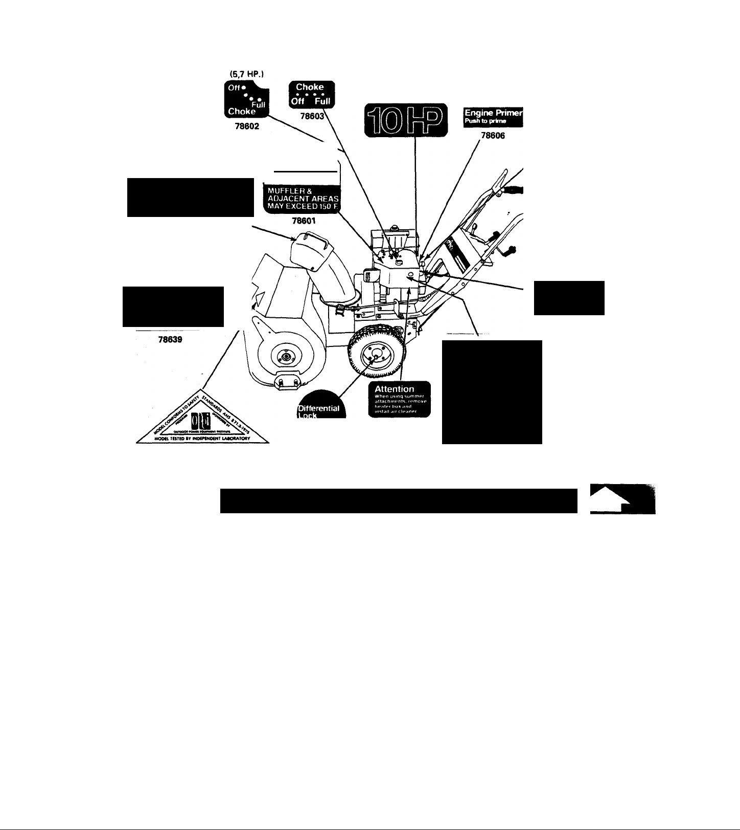
CHOKE: Move choke to choke position to start
©
engine. Models 924046 and 924048 have choke on
top of heater box. Models 924050 and 924052 have
choke at rear of heater box.
PRIMER BUTTON: Injects gas directly into car
©
buretor. (A) Move choke lever to full. (B) Push
primer bulbtwo times. (C) Pull start rope three times.
If engine fails to start, repeat procedure from step
(B).
KEY SWITCH: Prevents unauthorized use. Turn on
to run, turn off to stop.
©
STARTER BUTTON: The starter button (i^ is found
oh all units equipped with electric starters. Plug the
©
120 volt cord into the starter block; plug the op
posite end into a convenient 120 volt outlet. Push
the starter button to start the engine.
OPERATION
BEFORE STARTING:
Fill engine crankcase with Ariens Sno-Thro oil 5W-20
when using Sno-Thro.
Fill fuel tank with fresh, clean, regular gasoline.
Do not mix oil with gasoline.
Make visual check with regards to safety precautions, ob
structions, lubrication and maintenance.
DIFFERENTIAL LOCK: Models 924048, 924050 & 924052.
The differential lock is located in the left wheel hub.
When preparing to blow snow, turn the differential lock till it
snaps IN. In this position the differential is locked and both
wheels turn together. Power is applied equally to both. To use
the differential, pull back on the knob and turn it to the
OUT position. This unlocks the differential for easy turning
with mower, vacuum or broom attachments.
If tractor is to be used with lawn attachments, be sure
heater box is removed and air cleaner installed. Follow de
tailed instructions packed with attachment.
NOTE:
Check for frozen throttle control and for frozen impeller fan
before starting engine. These problems arise in wet, slushy
snow. If the impeller is frozen, it is best freed by thawing
in a heated garage or other building. A frozen throttle control
may be freed by starting the engine and letting it run long
enough to heat up the carburetor and loosen the cable. The
best solution for both problems is preventing freezing. Allow
the engine to run for a short time before shutting down to
throw the remaining slush and water out of the blower
housing and thus prevent freezing of the impeller fan. On
5 and 7 HP Models move throttle control to "FAST" position
after engine has stopped to minimize throttle damage due to
freezing. On 8 and 10 HP Models move throttle to "SLOW"
position after engine has stopped to minimize throttle damage
due to freezing.
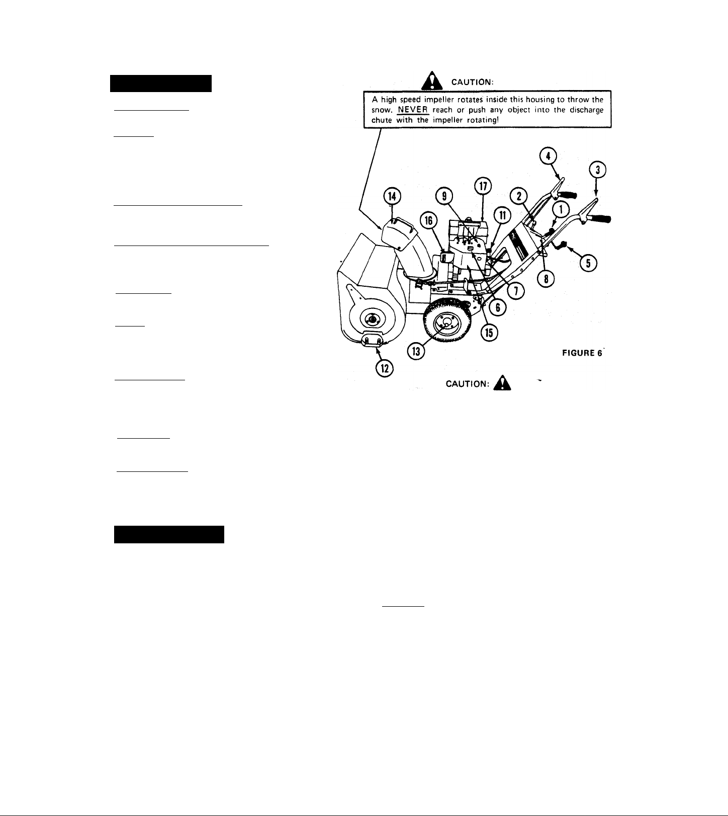
TO ST ART: Controls are identified in Figure 6.
Turn key to "run" position.
Move choke lever to CHOKE position:
Move throttle to FAST position.
Push primer bulb (l) 2 times.
Pull recoil starter nn to start engine. If the machine is
equipped with an electric starter attach the starter cable to the
starter switch, plug the cable into any convenient 120 volt
electrical outlet ■ and depress the starter button to crank and
start the engine. Follow the starter manufacturers instructions
supplied with the starter.
Move choke ^6^ to no choke gradually as engine warms up.
- 4 -
Page 5
TO TRANSPORT:
Move speed selector to desired speed.
Press down on handle bars to raise front of Sno-Thro
slightly off the ground.
Depress wheel drive clutch lever to transport unit.
TO OPERATE:
Move deflector to desirwJ height.
Turn hand crank direct discharge chute.
Depress attachment clutch (£) to engaged position.
Move speed selector to desired speed.
Move throttle (T) to desired speed.
Depress the wheel drive clutch lever to move tractor.
Speed of the machine is controlled by the throttle and
speed selector.
TOSTOP:
Release wheel drive clutch lever Qj Depress attachment
clutch lever ^ to allow the Sno-Thro to run for a short
time to throw out slush and water and prevent freezing the
impeller fan.
Turn key(^ to "off" position to stop.
5 and 7 HP Models: Move throttle to "FAST" position after
engine has stopped.
8 and 10 HP Models: Move throttle to "SLOW" position
after engine has stopped.
NOTE: This Sno-Thro is equipped with a mechanics/ interiock between wheel drive dutch and attachment dutch levers.
When both dutch levers are engaged the mechanical interlock
mil engage and the attachment dutch will remain angled as
long as the wheel drive dutch lever is not released. This frees
the right hand to operate other controls. Once the mechanics/
interlock is engaged, both the wheel drive and attachment
clutch levers must be released to disengage the attachment
drive.
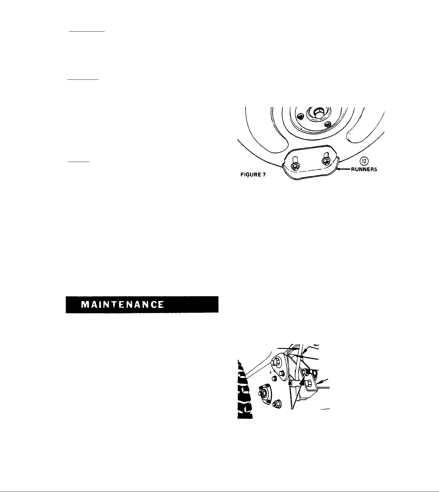
RUNNERS AND SCRAPER BLADE
The runners on each side of the blower housing, and the
scraper blade, along the back of the blower housing, are all ad
justable to suit conditions. Raising or lowering the runners
controls the distance the scraper blade is held above the sur
face being cleared. Runners are adjusted by loosening the two
nuts securing each runner. Move the runner to the desired
position and retighten the nuts. Be sure to adjust both runners
to the same height to keep blower housing level. Uneven
runners make the machine difficult to steer and will result in
an uneven clearing job.
Adjustment of the runners is critical to good cleaning. If the
machine is to be used on a gravel surface lower the runners
so the. blower will not pick up gravel then after the remaining
snow is packed down, the runners may be raised for close
scraping. On smooth concrete or blacktopped surfaces, the
runners may be raised so the scraper blade rests on the sur
face and scrapes clean.
The scraper is adjustable so it may be lowered to compensate
for wear. If the blade is allowed to wear down too far the
blower housing may be damaged.
ATTACHMENT CLUTCH ADJUSTMENT
The Attachment Clutch is adjusted by connecting the chain
to the spring just below the clutch handle. Connect the spnnii
to a chain link so the chain is snug but so the idler drops away
from the belt with the handle all ^e way up.
Ariens Company recommencte that you have adjustments
made by your local Ariens dealer. He has the tools and know
how to properly perform these maintenance adjustments
which may be required to Heap the Sno-Thro operating at
peak efficiency. The Sno-Thro is equipped with the finest
quality engine obtainable. However, should servicing be
required, it can be obtained from an Ariens dealer or an
authorized engine manufacturer's service station. Should you
decide to make adjustments on your Sno-Thro yourself,
Ariens recommends that you call your dealer for the answers
to any questions that might arise in performing this work.
SHEAR BOLT REPLACEMENT —_
Occasionally a small object may enter the collector and jam
the rakes. When this occurs, the shear bolts securing the rakes
to the shaft will break and allow the rake to turn freely on the
shaft preventing damage to the gear drive. When this happens,
turn off the engine, remove wire from spark plug, remove the
broken shear bolt and replace with a new ARIENS shear bolt.
Use of any other type of shear bolt may result in severe
damage to the machine. USE ONLY ARIENS SHEAR BOLTS
FOR REPLACEMENT.
WHEEL DRIVE CLUTCH ADJUSTMENT
A drive disc adjustment is provided to compensate for wear
on the friction wheel. If slippage occurs when the wheel
drive clutch it engaged, tighten the drive disc adjustment. This
adjustment is accessibie without removing the bottom cover.
See Figure 8.
CLUTCH ROD
ADJUSTMENT NUT
Adjust as follows: Place speed selector between first and
reverse. Tip machine forward on blower housing. Tighten
the adjustment nut while turning the wheels until the wheels
begin to bind. Back off 3 turns. Wheels should then turn
easily.
TOP OF SLOT
1/16" CLEARANCE
CLUTCH LEVER
FIGURE 8
Page 6

CHUTE CRANK ADJUSTMENT
In the event the chute crank fails to rotate freely, loosen the
nut securing the worm clevis to the bracket. This hole in the
bracket is slotted to permit adjustment. Position the worm
so there is a little clearance between worm and the gear
teeth on the blower. Tighten the nut. Rotate the discharge
chute through its full travel to see that it turns easily. Re
adjust if required. Uubricate as described under LUBRICATION
for smooth operation.
BELT REPLACEMENT
CAUTION
Since replacing the belts will involve turning the engine over
with the starter, and the engine might accidentaily start, re
sulting in injury, the spark plug wire MUST be disconnected
during this procedure.
The drive belt and the attachment drive belt are both accessible
by removing the blower housing as follows;
1. Remove the hair pin cotter in the chute crarik assembly.
Separate the chute crank.
2. Remove the two flanged whizlock screws securing the belt
guard to the tractor. Remove the belt guard.
NOTE: Tipping the tractor back on the handlebars when
separating the units may result in bending the bottom cover.
To avoid diis situation, either tip the unit up on the blower
housing and remove the bottom cover before separating the
units; or support the handlebars so the tractor does not tip all
the way over; then lift off the blower housing.
3. Remove the cap screws on each side that secures the blower
housing to the frame. As the blower housing and tractor
are tipped apart, roll the belt off the engine sheave between
the sheave and belt finger. This can be easily done by
pulling the recoii starter rope to rotate the engine sheave.
With the beit disconnected, the biower housing may then
be lifted from the frame.
A
REPLACEMENT OF TRACTOR DRIVE BELT (See Figure 10.)
The drive belt is held in place on the sheaves by an idler
pulley. To free the belt, the idler can be pulled from the
belt and the belt removed from the sheave. Activate clutch to
gain clearance. It may be necessary to pull back blower idler
arm clevis pin for additional clearance.
To replace the belts, position on the engine sheave first,
then on the drive sheave. .Position the idler carefully on the
belt.
With the belt in position and the idler in place, check the
belt alignment. The engine sheave and the tractor sheave must
align with one another WITH THE TRACTOR CLUTCH
ENGAGED. If the sheaves are not properly aligned, loosen the
setscrews on the engine sheave and align the sheaves. Re-tighten
the setscrews. Recheck the belt alignment WITH THE CLUTCH
ENGAGED.
ENGINE
REPLACEMENT OF THE ATTACHMENT DRIVE BELT
The sno-thro attachment drive belt is on the sheave on the
blower housing. To replace this belt, hold the impeller brake
away from the belt and slip the belt from the sheave. See
Figure 9.
Replace the belt by slipping it into position on the sheave;
positioning the brake shoe on the belt.
REPLACEMENT OF BLOWER HOUSING (See Figure 11.)
Position the blower housing on the rod in the tractor frame
and secure as follows:
1. Tip the blower and tractor together. Hold the attachment
drive belt up as the units are tipped together. Secure with
two cap screws into the frame. As the cap screws are
tightened, hold up on the handlebars to be sure the two
units are secured together.
- 6
Page 7

2. Roll the attachment belt on to the engine sheave. Pull the
recoil starter rope to turn the engine sheave and roll the belt
into place under the belt finger.
3. Check the belt finger spacing. There should be 1/8 inch
clearance all around the belt finger and belt with the
attachment clutch engaged. Readjust the belt finger if
required.
4. Check the sheave alignment with the attachment belt in
place. Readjust the position of the blower sheave as re
quired to align the sheaves. Be sure the brake pad aligns
with the blower sheave.
5. The idler on the attachment belt is adjustable. If the belt
slips, adjust the idler in the slot in the idler arm to apply
more tension to the belt. Belt should declutch when
attachment clutch is disengaged.
6. Replace the belt guard and chute crank assemblies.. Re
adjust the chute crank as described in the paragraph above.
Replace the spark plug wire.
DRIVE CHAIN ADJUSTMENT
MODELS 924050 and 924052
If sno-thro is difficult to push because of tight or inter
fering drive chains, proceed as follows:
1. Stand unit up on blower housing and remove bottom cover.
2. Chain tension is adjusted by loosening the two nuts on
the 24364 Reduction Shaft. Adjust reduction sprocket
up or down in slot to obtain proper tension (chain should
be snug). Retighten both nuts. Torque to 170-180 inch
lbs.
3. Chain interference with the 3085 Bearing Flange on 24045
Hex Shaft occurs if these is no 64058 Washer between the
10276 Sprocket and 54079 Bearing. Install washer.
LUBRICATION
FIGURE 12
REPLACEMENT OF FRICTION WHEEL
1. Tip the machine up on the blower housing and brace
securely. Remove two cap screws and loosen the other two,
securing the bottom cover and remove the cover.
2. Place the speed selector in FIRST position. Depress the
wheel drive clutch lever to hold the friction wheel while
the five bolts securing the friction wheel to the hub are
loosened. Remove the five bolts, shift to THIRD position
and disconnect the shift link. See Figure 12.
3. Position a new friction wheel on the hub and replace the
five bolts. Tighten these bolts to 8-10 foot pounds with
a torque wrench. Replace the shift links.
4. Replace the bottom cover. Readjust the drive disc as
described in the WHEEL DRIVE CLUTCH ADJUSTMENT
on page 5.
Fill crankcase with Ariens Sno-Thro oil 5W-20 when
using Sno-Thro at temperatures below 40 degrees F.
Use Ariens Gard-N-Yard oil MS classification SAE-30 when
using lawn attachments at temperatures above 40 degrees F.
Fill fuel tank with fresh, clean, regular gasoline.
NOTE:
For detailed instructions on engine refer to manufacturer's
booklet packed with the machine.
-7 -
Page 8

TRACTOR DRIVE
MÓDEL 924052 GEARCASE
At start of season, grease gears, pinion sprocket, hex and axle
shaft as indicated in Figure 13. Use Ariens Moly Lithium grease.
Put two or three drops of light oil on speed selector and other
linkage points. CAUTION: Do not allow grease or oil to
come in contact with friction wheel, drive disc or belts.
SNO-THRO UNIT
ZERK FITTINGS
SHEAR BOLTS
OIL FILL
Check oil level periodically. Oil level must be up to oil fill hole.
Change oil every 25 hours or once each season which ever
comes first. Fill with Ariens Special L-2 Gear Lubricant.
Approximately 5 oz.
FIGURE 15
FIGURE 14
NOTE:
When replacing a worn or broken shear bolt, use
shear bolts only.
Grease rake shaft periodically or each time a shear bolt is re
placed. At the end of the'season, remove shear bolts, use a
grease gun on zerk fittings to grease rake shaft, turn rakes on
shaft several times and replace shear bolts. See Figure 14. Use
Ariens Moly Lithium grease.
ARIENS
MODELS 924046,924048 8i 924050 GEARCASE
The blower gear case is lubricated with Ariens Liquid
Grease (Part No. 000070). This grease will not flow at lower
temperatures. It is therefore difficult to Check the lubricant
level. Best method for checking is to place the unit in a warm
location overnight. This allows the grease to flow to level.
Check the lubrication by removing the filler plug on the side
of the gear case just above the left auger shaft. Lubrication
should be even with the hole with the machine sitting level. It
may be necessary to insert a wire into the hole to check level.
The unit will not be damaged by over lubricating.
STORAGE
ENGINE: Follow detail instructions in the engine manual.
SNO-THRO: Lubricate, clean and repaint as necessary.
Cover and store in dry place.
- 8-
Page 9

24" & 32" SNOW-THRO FOR
MODELS 924046, 48,
50&52
SNO-THRO DE ET 32"
MODELES 924046, @H
48, 50 ET 52
USE ARIENS L-2
GEAR LUBRICANT
APPROX. 5 OZ.
Page 10

24" & 32" SNOW-THRO FOR MODELS 924046, 48, 50 & 52 SNO-THRO DE 24" ET 32" MODELES 924046, 48, 50 ET 52
NoDE
NO DE CODE '
REF.
PIECE D'INV
„ „ DESCRIPTION
REF.
N0.
11 024383
PART STOCK
NO. CODE
1
0243790GEARCASE, L.H. Half
2
0243800QEARCASE, R.H. Half
3 055122S
4
056081
5
024382
6
058045
7
032103STHRUST COLLAR
8
055111
9
055112
056047
10
FLANGE BUSHING
M SEAL
WORM SHAFT & GEAR
S
M GROOVE PIN
FLANGED BUSHING
s
FLANGED BUSHING
s
M
"0" RING
0 RAKE SHAFT
024065
0 RAKE SHAFT
12 058069MGROOVEPIN
13
14
058030
064166M
M ROLLPIN, 3/16x1)4"
WASHER
15 032038M GASKET
16 082054MCARRIAGE BOLT
17
18
19
062013M
070010M FLGOWHIZLOCKSCREV)/
024237
CARRIAGE BOLT
FAN
0
0243760 FAN
20
058037MROLLPIN, 1/4 X 1-3/4"
21 072108FVEE BELT
072086FVEEBELT
22
23
062010M
060012M SETSCREW
24 024434
CARRIAGE BOLT, 3/8-16x6
0 CHUTE CRANK BRACKET 1
25 0243490DISCHARGE CHUTE
26 059023M
024403
27
074054
28 010193M
29
30
510012sDEFLECTOR CHUTE
065039M LOCKNUT
31 0244050
32 024389
33
34
35
36
37
073070
066001M
0243460
059001MCAP SCREW, 1/4-20 x 3/4
056070M
38 024013
39
40
41
42
43
44
45
002008M GASKET
055059M flanged bushing
5240CfiM WORM AND WORM GEAR
001138MPIPE PLUG
024002
057075M
065040M
46 010142
0 DISCHARGE CHUTE
CAPSCREW, 3/8-16x3/4
M TAPTITE
WING NUT
BRAKE ARM EXTENSION
S PULLEY HUB
s
SHEAVE
KEY,Woodruff, 3/16x7/8
ROD
SEAL
0 GEARCASECOVER
s
GEAR CASE
•SNAP RING
LOCKNUT
s
BEARING FLANGE
031859sBEARING FLANGE
47
48 075083
49
50 054044
51 624065M
52 024461
53
54
55 058034
56
57
58
59
010198
s
s KNOB
624035M
s
022123
024427
s
M
s WORM GEAR, L.H.
M ROLLPIN, 1/2 X 3/4
063023M
065042
M
010438M
524036
524037
524038
0
0
0
CAP
BRAKE ARM ASSEMBLY
BEARING CUP
UNIVERSAL JOINT
CHUTE CRANK
WORM CLEVIS
LOCKWASHER
LOCKNUT
CHUTE CLAMP
BLOWER HOUSING
BLOWER HOUSING
BLOWER HOUSING
QUANTITE'
NO. REd'O
CO o
CO
^ S lO
o o e
s
^ wr ^
CN
03 os S)
a>
1
1
1
1 1
2
2 2
2
2 2
1
1 1
1
1 1
1
1 1
1
1
1
1 1 -
1
1
1
1 1
-
-
1
1 1
2
2 2 2
2
2 2
1
1 1
2
2 2
- -
1 1 1
1
1 1
-
-
2
1
-
2
-
2 2
- 1
1
w
1
6
6
2
2 2
1
1
1 1 -
-
-
“
2
6
1
1
6
«
1
1
1
1 1 1
-
-
-
-
- -
-
- -
-
- - -
3
1
-
1
1
1 1 1 1
-
2
1
1
1
3
1
2
2
6 8
6
1
1
1 1
1
6 6
6
-
1
1 1 1
1 1 1
1
1 1
-
-
-
-
- -
- -
-
-
-
- -
3
1 1
- -
1 1 1 106
1 1 1
-
-
2
2
1 1 1
1
1
1 1
1
3 3 3
1
1
5 5 5 6
3 3 3 4
1
1
-
-
-
1
- -
1
1 1
-
1 1
3
Node No OE CODE
REF, PIECE D'INV,
REF. PART STOCK
DESCRIPTION
NO. NO. CODE
_
60054063
-
-
- 031860
-
-
-
054052SBALLBEARING--
61003017
064002M
62
63010164
024373
64054045
-
-
1
-
029225
070058M
66
67024374
68065056M FLANGED WHIZLOCK NUT10
010165MRUNNER
65
69 064047M
-
70063006
-
71059024M
72022093
73 510015
2
-
74
524039
524013
_
-
4
1
2
524014
76
524035
77
524030
010494D
79
065015M NUT
80
010260
81
067019M
82
002005
83
084046M WASHER, 1.505 x 1.0052
84
524040
75
1
85
1
86062011
87058015
88
-
89
90
91 070060
92
1
93024345MCLEVIS PIN
4 94
2 95
1 96
97
1
98
2
99
1
100
1
101
1
102
1
103
3
_
104059022
105
1
107 064082
108
2
108
2
109 070026M
110
1
111074027
112
113 024381
1
114
115
116
-
-
S RADIAL BEARING
S BEARING FLANGE
S BEARING FLANGE
WASHER,5/16x7/8x.083
M
SCRAPER BLADE
M
SCRAPER BLADE
BEARING CONE
s
M RUNNER
RIBBED NECK BOLT6
BEARING SUPPORT
s
WASHER, .516x1.441x1/8 22 2
M
LOCKWASHER2
CAP SCREW, 1/2-13x1
M SPIN DRIVE ZERK FITTING 4
F
SHEAR BOLTW/NUT
s
RIGHT RAKE
s
RIGHT RAKE
s
LEFT RAKE 1
s
LEFT RAKE
s
GEARCASE ASSEMBLY, 32'
s
GEARCASE ASSEMBLY, 24'
WORM SHAFT11 1 1
M WAVE WASHER
HAIR PIN 1 1 1 1
M BEARING SPACER
083164
063032M
M
SPRING 1
CARRIAGE BOLT, 5/16-18 X 1
M
ROLLPIN, 5/16x1-3/4
M
LOCKWASHER1 1
070031M FLGO'WHIZLOCK SCREW!! 2
0243750
0240150
WORM SHAFT
RIBBED NECK BOLT
M
ADJUSTMENT PLUG
065078MFLANGED WHIZLOCK NUT 3
056061FSEAL
063017MLOCKWASHER
055035
064087M
FLANGE BUSHING
s
WASHER, 1.626 X 2.5 X.012
022178M BRAKE LINING11 1 1
068062M RIVET
067010
024064
004037
M HAIRPIN COTTER
GEARCASESHAFT
0
DUST CAP
s
CAP SCREW, 5/16-18x3/4
M
063003M LOCKWASHER
066008M
067010
067004
KEY,Woodruff No.6-
M
WASHER
M
HAIRPIN
M
COTTER PIN
NUT RETAINER
062001M
062026
066013
059028
065056M
CARRIAGE BOLT2
M
TAPTITE 2
M
CARRIAGE BOLT
M
WORM GEAR1
M
KEY, STRAIGHT
M
CAP SCREW
WHIZLOCK NUT
1
OUANTITE'
NO. REQ'D
CO
00 O <N
^ LO Un
s
eoo
^ ^ ^
CN
<N CN CN
03 03 03
03
1
1
1
1
-
9
1
-
-
2
-
2
-
1
1
-
-
9
9
1
-
-
10
1
- 1
- 2
2 2
-
-
6
6
2 2 2
1010 6
2
2
2 2
2 2
4 4
2
1
- -
- «
- -
1
1
1
2 2
2
1 1
-
1
1
-
1 1
1 1
1
1 1 1
- -
2 2
2
1 1 1
-
-
1 1
1
-
1
2 2
-
-
3 3 3 3
-
1
- - -
- ■ -
2
_
2
-
-
1 1
3
2
-
2
3
-
2
-
2 2
1 1 1 1
- - -
-
- -
- - -
_
-
- _
-
- -
1
2
—
1
2 2
1
- —
2
2 2 2
2
2
5
5
5
1
— _
-
-
1
—
1
_
1
-
_
2
6
4
-
I
-
1
2
2
-
1
-
1
1
-
2
2
2
1
1
3
4
2
2
1
1
2
_
2
6
1
_
1
1
1
1
1
1
1
SUGGESTED PARTS STOCKING CODE
F -FAST S -SLOW
M -MEDIUM O -CUSTOMER ORDER ONLY
F — FAST (rapidel S - SLOW (lent)
M - MEDIUM (moyen) 0 - Commande du client seulement
■ 11
CODE SUGGÉRÉ D'INVENTAIRE DES PIÈCES
Page 11

TRACTOR PARTS FOR MODELS ) 924046, 924Û48,
PIECES DU TRACTEUR DES MODÈLES f 924050 & 924052
REO ROUGE
CAUTION
I ORDER PARTS BY PART NUMBER
NOT BY REFERENCE NUMBER OR
DESCRIPTION. ANY PART
I ORDERED BY REFERENCE
NUMBER WILL BE DISREQARDED.
-12-
ATTENTION
COMMANDEZ LES PIECES PAR
numero, non par
numero DE RÉFÉRENCE NI PAR
DESCRIPTION. TOUTE COMMANDE
PAR NUMÉRO DE RÉFÉRENCE
SERA ICNORÉE.
Page 12

TRACTOR PARTS FOR MODELS
924046, 924048, 924050 & 924052
PIECES DU TRACTEUR DES MODELES
Node N0 DE CODE
REF. piece D'INV
»re CT«»., DESCRIPTION
REF. PART STOCK
NO. NO. CODE
FLANGE WHIZL0CK SCREW
1 070009
2 060012
3 063003
4 024074
5 024073 M
6 065040 M
7 059028 M
8 024236
9 010142 s
9 024363
10 054136
10 054093
11 065056
12 070058
13 070015
14 024077
15 070011
16012023SBEARING SUPPORT
17 055039
18 003017
19 024338
19 024045 0 HEX SHAFT 20 066015
21 010276 s
22 025089
23 064058
24 003085 S BEARING FLANGE
25 054080 S BEARING, RADIAL
26 065054MLOCKNUT
27 065094
28 024366
28 024339
- 29 022063 M
30 065018
31 063014 M
32 064093
33 055040MBUSHING
34 024364
35 024367
36 064036 M WASHER .В5/.в35х.005х.062 5 5 5 5
37 058009 F
38 055026 M
39 058029FROLL PIN 3 3
40 063025
41 610938 0
41 624074
41 624083
42 055029 M SLEEVE BUSHING
43 010374sPIN 1 1 1
44 083007
45 058042MGROOVE PIN 1
46 010372 F
47 058032
48 010375 S KNOB 1
49 067001
50 024233
51 024232 S LEVER SHIFT ARM
52 012151 S CLEVIS PIN 2 2 2 2
53 059039
54 059136
55 024231 0
56 024115
57 065042
M
SETSCREW 1
M
M LOCKWASHER
M PINION CHAIN
IDLERCHAIN
M IDLER CHAIN
012078
LOCKNUT
CAP SCREW y.-20x)4 2 2
M BELT FINGER
BEARING FLANGE
BEARING RETAINER ■
s
M BEARING BALL
M BEARING,RADIAL
LOCKNUT
M
F RIBBED NECK BOLT
FLANGE WHIZLOCK SCREW
F
SHAFTSUPPORT
M
F RIBBED NECK BOLT 6
M FLANGED BUSHING 2
M BEARING FLANGE 2
6 HEX SHAFT
M KEY, WOOD RUFF 1/8x5/8
9 TOOTH SPROCKET 1 1
s ROLLER
M WASHER .500/.505x1x.062 2 2
F LOCKNUT
SHAFTSUPPORT 1
S
S CLUTCH STOP
SPIN-DRIVE ZERK FITTING
F
NUT
LOCKWASHER
F
WASHER .380/.385x3/16x.062
S REDUCTION SHAFT •
S
PINION SHAFT
ROLL PIN
FLANGED BUSHING
F
LOCKWASHER
AXLE ASSEMBLY L.H.
0 AXLE LH. -
AXLE ASSEMBLY L.H. 1
0
s SPRING
LOCKNUT, HOB 1
F
ROLL PIN 3/32x1
F
COTTER PIN
S SHIFT LINK
M CAPSCREW 5/16-18x14
M CAPSCREW 5/16-18x3
BRACKET SHIFT LEVER 1 1
SPACER
s
F
LOCKNUT
SUGGESTED PARTS STOCKING CODE
F - FAST S -SLOW
M - MEDIUM 0 - CUSTOMER ORDER ONLY
QUANTITÉ
Ш eoo»
1 I I
(N СМеМ
OB 99 Ç
8
5 5
1 1 •
2
1 1
6 6 6
■ - - ■ 8
9 9
4 4
2
1 1
1 1
1 1
1 1
1 1
4 4
1 1
1 1
4 4
3
2 2
1 1
4 4
1 1 1 1
1
3 3 3 3
NO. RÉQ'D
0999 99
8 8
8
1 1
1
5 5
1 1
•
1
2
-
2 •
2 2
2 2
•
2
9
4 4
• 6
•
• -
•
1 1
1 1
1 1
•
2 2
1 1
1 1
1
1
4 4
1
1 1
2
2
2 2
2
2 2
2 2
4
3
1
1
2
1
1
3
4 4
1 1 1
Sa a
OO O
- -
1 1
1 1
1
1
1
1
1
1 1
1
1 1
3
2 2
1
1 1
Node No DE CODE
REF. PIECE D'INV.
REF. PART STOCK DESCRIPTION
NO. NO. CODE
58 067002
59 024069 0
60 024272 0
1
2
2
1
8
9
1
1
2
2
1
4
3
1
1
1
1
1
1
3
1
61 083094
62 624027 s
63 010542 s
64 065062
65 054039
66 022002 s SPINDLE HOUSING
67 024155 s BEARING SPACER
68 022003
69 003034 M
70 024076 s SPINDLE
71 010546 M DRIVE PLATE
72 024071
73 064123 F
74 059003
75 063018 M
78 065015
77 010485 S STREET ELBOW
78 012222
79 025208 M CAP
80 075040
81 075050
82 022161
83 624022 0 CARRIER 1 1 1
84 65086
85 054093
86 064071
87 057021
88 024454 s
89 003003
90 065077
91 024455
92 059022
93 024228 0
94 024086 s
95 024227
96 022135 s
97 524002 0
97 524032 0
98 624072 0
99 024081
100 066006 M
101 055057 M
101 055029
102 024141
103 055126
104 013136
105 073049
F - FAST (rapide) S - SLOW (lent)
M — MEDIUM (moyen) O — Commande du client seulement
-13-
F
COTTER PIN 3/32x1 2 2
FORK PIVOT ROD 1
CLUTCH FORK 1 1
SPRING
S
SPRING ASSEMBLY 1
ADAPTER SPACER .
M
LOCKNUT, NYLON
M
BEARING, BALL
s DRIVE SPINDLE HOUSING
ROLLER
M
DRIVE DISC SPACER
WASHER, 5/16x11/16x.065
M CAPSCREW 5/16-18x1
LOCKWASHER
F
NUT
M
NIPPLE
0 BUTTON PLUG 1 1 1
SNAP BUSHING
M
0 SHORTING WIRE 1 1 1
M LOCKNUT
M BEARING, RADIAL 1
M
WASHER 1
M SNAP RING' INTERNAL
DISC HOB 1 1 1
F FRICTION DISC
M
LOCKNUT 1
SPINDLE HUB 1 1 1
s
M
CAP SCREW, 5/16-18x3/4
CLUTCH ENGAGEMENT YOKE
SPACER
s ADAPTER
ROD ADAPTER
PINION 8i SPROCKET
PINION & SPROCKET
SPROCKET ASSEMBLY
s
CARRIER SHAFT
WOODRUFF KEY
BUSHING
M
BUSHING
M
BEARING FLANGE
M SPACER
M
ZERK FITTING
M
PULLY
CODE SUGGÈRE D'INVENTAIRE DES PIÈCES
QUANTITÉ NO, REQ'D
CO 00 09 о ^
H « s 'A £ ^
о о о о о о
^ ^ ^ ЧГ
«N ГМ <М «N esj
09 09 09 09 09 09
2 2
1
1 1
1
1 1 1
1
2 2 2
1
1
1 1 1
1 1
1
1
1
1
1
3 3
4
1 1 1
1
1
1
1
1 1
1 1 1 1
1
1 1 1
1
_
1
1 1
1 1
1 1
1 1
1 1
1
1 1
1 1
4
1 1 1
1
1 1
1 1
1 1
1
1 1
1 1
1
_
1 1
1
1
_
2
1 1 1
1 1 1 1
1
1
1
1 1 1
1
1 1
1
1
1 1
3
4
1
1
1 1
1 1
1
1 1
1
1
1 1
1
1
1
1
1
1 1
2 1
1 1
1 1
1
1
1
1
1
1
3
4
1
1
1
1
Г
1
1
1
1
1
1
1
1
1
1
1
_
1
1
1
1
1
Page 13

TRACTOR PARTS FOR MODELS \
PIECES DU TRACTEUR DES MODELES )
924046, 924048,
924050 & 924052
• 14-
Page 14

TRACTOR PARTS FOR MODELS
924046, 924048, 924050 & 924052
PIECES DU TRACTEUR DES MODELES
924046, 924048, 924050 & 924052
Node no de code QUANTITE
REF. PIECE D'INV « -,
REF. PART STOCK “ASCRIPTION | |3
NO. NO. CODE 8 8S
1 070008
2 024406
3 072088
3 872066FVBELT
4
5 058053
6 063032
7
1 084002
9
9 024357 s ENGINE SHEAVE
to 066818
t1
12
13
14
14
IS 075006
18 810860
IS 603002sWHEEL ASSEMBLY
16
17
18 068105
18
18
18 024433MCLUTCH ROD, Trector
20
21 532008MCLUTCH HANDLE, Attechment 1 1 1
22
23
24
25 064033MWASHER, .7501,760 x 1.375 x .1251
26 063004
27
28
28
30 064007
31
32
33
34
35 032010 s LEVER
36
37
38 058003
38
40
41
42
43 024322
44
44
44
4S
46
47
47
48
48
50
51
52
53
53
54
55
M FLANGE WHIZL0CK SCREW 4 4
F
BELT COVER
F
VBELT 1
M SETSCREW
080012
M CAP SCREW, 5/16-24x3/4"
M
LOCKW ASHER 2 2
M
024253
024021
024435 0 HANOLEBAR PANEL
024447 M
024U8
024432
024431MUPPER HANDLEBAR
603848
075018
068124
0244U M CLUTCH ROO.Tttctor
532007
065051MKEPS NUT
074038
022128 s HANDLE PIVOT
065018
024442
024441
065042
0244280ACTIVATING SHAFT 1 1
024456sCLUTCH ROD ATTACHMENT 1 1 1
058026FROLL PIN
024428 s LEVER
055037 M
024354
067001
066011MKEY, Feether 3/16 X 3/16 X 1-1/4
065031MNUT
010370MAXLE, R.H.
024371MAXLE, R.H.
024408MAXLE ASSEMBLY. R.H.
0630180LOCKW ASHER
024430
024437
024436 0
066012
058003
058068 M
010358
070015
064036
064170
003377
010366 s
BELT FINGER
M
WASHER. 5/16 X 7/8 x .083 4
s ENGINE SHEAVE 1
M KEY.Stniiht 1/4 X 1/4 X 1-3/4 1
LOWER HANOLEBAR. R.H. 1
M
LOWER HANOLEBAR, L.H.
M
UPPER HANDLEBAR 1
M
GRIP 2 2
s TIRE & WHEEL ASSEMBLY
Consists Of
M 071048 TIRE
M
071050 TUBE 2
s 071052 RIM 2 2
M
071062 TIRE
071037 TUBE, Aveileble
M
s 071076 RIM
s TERRA TIRE & WHEEL ASSEMBLY
M
071021 TURV SAVER TIRE
M 071067 TUBE AVAILABLE
071077 RIM
s
M
KNOB 1 1 1
F
THROTTLE CONTROL 1
F
THROTTLE CONTROL
M CLUTCH HANOLE.Trector 1
s TAPPING SCREW
F
LOCKW ASHER 4 4
F
NUT
s SHIFT ROD UPPER
s SHIFT ROD LOWER
F
WASHER, 1/4 X 47/64 X.065 1 1
F
LOCKNUT
FLANGED BUSHING 2
M CAP SCREW. 5/16-18x1
F
CLEVIS PIN
F
COTTER PIN 2 2 2
M
AXLE SHAFT
0
BOTTOM COVER
0
FRAME
FRAME
M
KEY,WoodruH1/4x3/4 -
M
ROLL PIN, 3/16x1-1/4
CAP SCREW, 5/16-18 x1-1/4
s
SPACER
F
FLANGE WHIZLOCK SCREW
F
WASHER, .87S/.885 x 1.385 x .062
F
WASHER, .87S/.885X 1.385 x .062
0
HUB CAP
PUSHNUT
NOTE: FOR OECALS SEE PAGES 2 & 3
NOTE: OECALQUES (voir p. 2 & 3)
NO. REQ'D
liii
1 gs я
i •» •» m
1 1 1
- 2
2 2 2 2
1 1
- -
1
1 1 1
_ _
2 2
2 2
- -
- -
-
- -
-
- - -
- -
-
- 1 1
- -
4
- 1
2
2
2
4 4 4
- 1 1 63 024222 s IDLER ARM 1 1
1
1
1
1 1 66
-
2
- -
•
- -
- _
2
2
2
-
2
2
-
-
-
-
-
- -
1
-
1
2 2 2
2
4 4
2 2
4 4
1 1 1
1
3 3
1 1 1
1
1 1 1
1
1 1 1
2
1 1 1
1
-
- -
-
1 \ 1
1 1
- 1 1
1
2
1
1
5
-
_ _
2 1
-
4
2
- -
4
4
1 1
3
1
2 2
2
1
- -
- - -
- -
1
—
-
1
_
_ _ _
_ _ _
1
1 1
S s
_ _
1
2
1 1
Node
No OE CODE
REF.
PIECE D'INV.
REF.
PART STOCK
NO.
NO. CODE
4
56 003376 8
57
070032 S
058003 M
56
1
58 056030
2
2 60
1
1
_
1
2
-
-
-
-
2
2 81 065042 M
2
2
1
1
1
4
2 94
4
4 87 002270 M
1
3 101
1
1
1
2
-
1
-
1
1
087014
58
612888 s
60
624073
010211 s
60
61 024348 s
012132 s IDLER
62
64 064052 M
65 010280 s
067004 F
67 083187 s SPRING
012131
BS
024347
68
024353 M RETURN CLIP
70
71 074054 F
72 024323MWHEEL HUB
624087
73
013157
74
75 065075MNUT 1 1
011031
76
77 024458
024460 0 BELL CRANK 1 1
78
79 064080 M
024457
80
82 055132 s SLEEVE BUSHING
83 065040 M
064037 M
84
055131
85
86 060036MSETSCREW
87
065088
024458 M
88
067018 M
88
80 067018
061057 M
81
83 063148 M
024443
083184 M
85
083183 M
86
88 062061 M
88 062062 M
too 058005 M
083084
102 062060
103 065058 M
064084
104
105
058150
106 058131 M
107
024448 M
075086 M
108
108 057086 M
110 075085 M
111
024466
111 024467
065078 M
113
114
058050 M
058132 M
115
067024
116
117
068012
118.
075060
SPINDLE CUP
WHEEL BOLT
ROLL PIN, 3/16x1-1/4
M
ROLL PIN. 3/16 X 1-1/2
M
COTTER PIN
DIFFERENTIAL ASSEMBLY
s DIFFERENTIAL ASSEMBLY
SPUR GEAR
IDLER ARM 1 1 1
WASHER, .380/.385 x 13/16 x 24 1 1
WAVE WASHER
COTTER PIN
BEARING SPACER 1
s
0
BRACKET
TAPTITE
M
KEY SWITCH
s IGNITION KEY
s SPACER 1 1
0 SLIDER 1 1
WASHER
s
CLEVIS
LOCKNUT
LOCKNUT
WASHER
s SLEEVE BUSHING
M
NUT
CLEVIS PIN
HAIRPIN 1 1
M
COTTER PIN
MACHINE SCREW. 10-24 x 1/2
SPRING 1 1
s PIVOT 1
SPRING 1
CLUTCH SPRING 1 1
CLUTCH CHAIN 1 1
CARRIAGE BOLT, 5/18-18x5/8 2 2 2
CARRIAGE BOLT, 5/18-18 XI»
ROLL PIN, 3/18x7/8 1 1
M
SPRING 1
M
CARRIAGE BOLT, 1/4-20 x 1» 4
FLANGEWHIZLOCK NUT
M
WASHER
M
CAP SCREW, 1/4-20 x IK Grede 5
CAPSCREW
ROD
KNOB
SNAP RING
SNAP BUSHING
M
STIFFENER. R.H.
M
STIFFENER, L.H.
FLANGEWHIZLOCK NUT
CAP SCREW, 1/4-20x1»
CAP SCREW, 1/4-20x1"
M
COTTER PIN 1 1 1 1
M
CLAMP 1 1 1 1
SNAP BUSHING
M
DESCRIPTION 1
1
5
2
1
QUANTITÉ
II ill
As Am s
mm mm m
•1
2
6 6 8
_
2
_
_
2
2
2
2
2
2 2 2 2
2 2 2
6
3
2
2
2
2
5
1
1
1
1 1 1 1
1 1 1 1
1
t 1 Î 1
1 1 1
1
4 4
2 2 2
1 1 1 1
NO. REQ'D
1
1
_
_ _ _
_
1
-
1 1
-
-
2
2 2
Î 1
2 2
1 1 1
1 1
1
1 1
1 1 1
2 2
-
-
1
1
1
t 1
1
2
2 2
6 6
3
3
1
1 1
2
2 2
2
2 2
1
1
2
2
1 1
1 1
2
2 2
1 1
4
4
5
5 5
1
1 1
1
1
1
1 1
1
1 1
1
1 1
4
t 1 1
1
8
1
_
_
t
1
1
2
2
1
1
1
1
1
1
2
6
3
1
1
2
1
1
1
2
1
4
1
1
4
2
SUGGESTED PARTS STOCKING CODE
F - FAST S -SLOW
M - MEDIUM 0 - CUSTOMER ORDER ONLY
CODE SUGGERE D'INVENTAIRE DES PIECES
F - FAST (r«pid«l S -SLOW(l«nt)
■IS' M - MEDIUM (mov»n) 0 - Comminde du client seulement
Page 15
DEALER
1. GENERAL
All hardware and parts required for assembly are shipped in
the parts bag pr are located, in place, on the machine. The
upper handlebars and panel are assembled at the factory with
the two clutch rods and interlock system in place and adjusted.
The lower handlebars must be installed. The snow head and
tractor are shipped assembled with lower shift rod in place.
Attachment clutch rod is in place on handle panel assembly.
Model 924052 (the 32" snow head) is shipped with the runners
and discharge chute detached and they will have to be
installed.
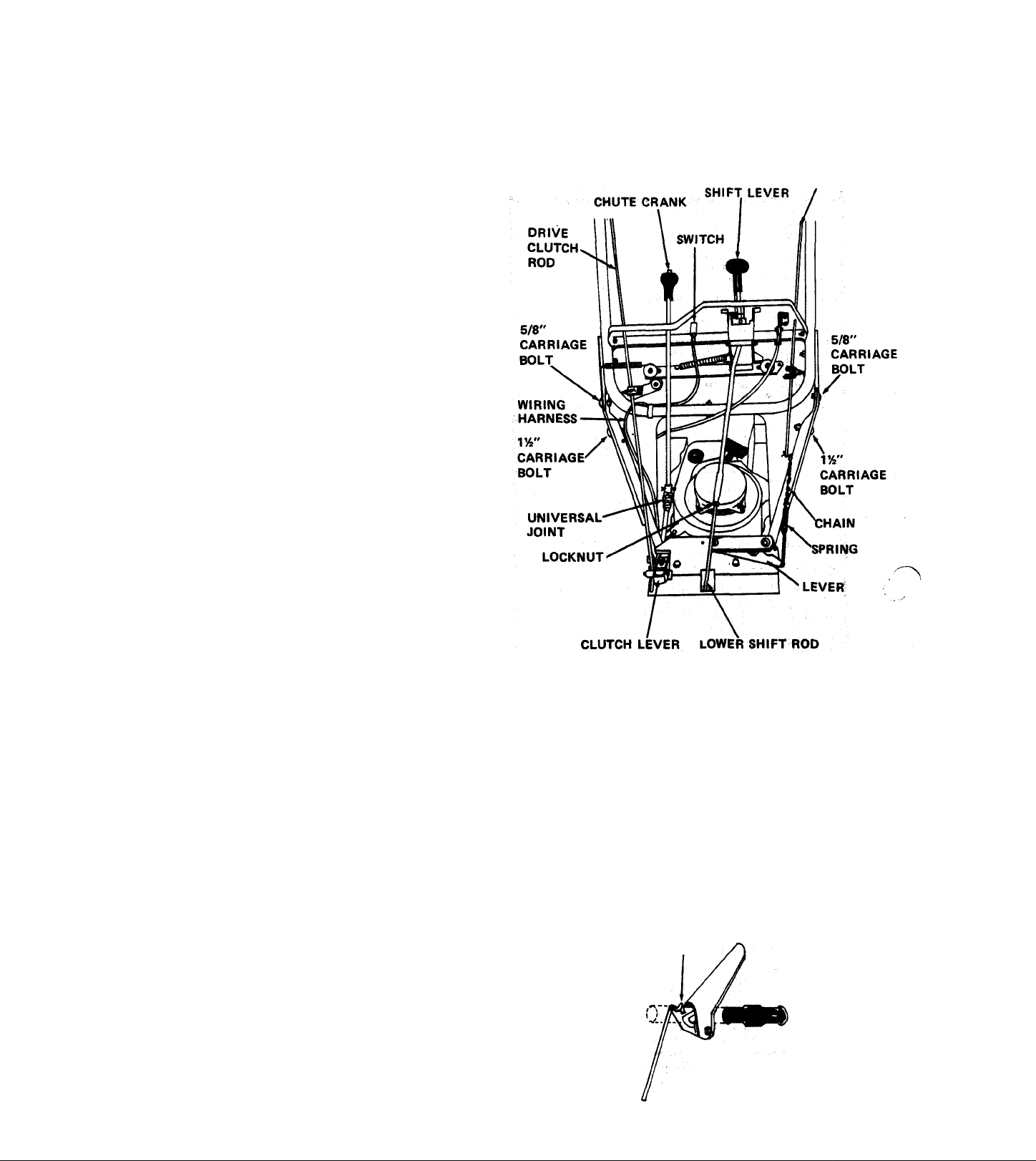
2. HANDLEBAR
Install the lower handlebars on the frame using the studs and
hardware in place on the frame. (Leave the hardware loose on
the studs until the upper handlebars are installed). Be sure to
install the chute crank bracket on the left rear stud on top of
the handlebar.
Install the upper handlebar and panel on the lower handlebars.
Use a flat washer on the outside of each cap screw. Use a 5/8"
carriage bolt and locknut in each of the top holes, and an
VA" carriage bolt and locknut in each of the lower holes. With
everything in place, tighten all handlebar hardware.
UP AND PRE-SERVICE
ATTACHMENT
CLUTCH ROD
3. THROTTLE CONTROL
Route throttle control under handlebar and insert into
position in handlebar panel. See Figure 16. Secure with
two machine screws #(10-24xVa) and two keps nuts
from parts bag. Install knob on throttle lever.
4. SHI FT CONTROL ROD
Remove the upper shift rod from the shift lever and place the
shift lever in REVERSE position. Pull up on the lower shift
rod which is already installed in the frame. Hold the lower
shift rod up while screwing the upper rod in place. Turn the
upper rod into the lower until the end of the upper rod
lines up with the hole in the shift handle. Install the upper rod
in the shift handle and tighten the locknut joining the upper
and lower shift rods.
S. ATTACHMENT CLUTCH ROD
The attachment clutch rod is installed in the upper handlebars
but the chain must be hooked to the spring already in place on
the clutch bell crank. Connect the spring to a link in the chain
that will keep the chain snug without pulling up on the bell
crank. The clutch idler pulley must tighten up on the belt
when the handle is down and must fall away from the belt
when the handle is upright. Adjust chain as required.
6. DRIVE WHEEL CLUTCH ADJUSTMENT
FIGURE 16
c. Position the clutch handle so that it is all the way up.
See Figure 17.Tighten the tractor clutch rod in the rod
adapter with the setscrew. With handle down, clutch
lever should come within 1/16" of top of slot in frame.
Adjust as required. See Figure 8 of owners section.
7. KEY SWITCH CONNECTION
The key switch is factory installed in the handlebar
panel and the wiring is connected to the engine. Route
the wiring harness up the inside of the panel, alongside
the lower handlebar. Connect wire harness to switch.
See Figure 16.
TIP HANDLE FORWARD
AS FAR AS POSSIBLE
a. The clutch handle is already positioned on the handle
bar and the tractor clutch rod is in place in the handle.
Check to be sure the clutch handle is free to fall down
on the grip.
b. Insert the lower end of the tractor clutch rod into the
rod adapter.
FIGURE 17
-16
Page 16

8. DISCHARGE CHUTE (MODEL 9240S2 ONLY)
The discharge chute is shipped with the four mounting clips
attached to the chute. Remove the clips and hardware. Po
sition the discharge chute on the blower housing. Secure with
the clips and hardware. Be sure the chute rotates freely.
13. BLOWER GEAR CASE
On 32" Models 924052, and 824008. Check the oil level in the
auger gear case. Oil level must be even with the oil filler hole.
Fill with Ariens Special L-2 Gear Lubricant. Replace the filler
plug.
9. DEFLECTOR
The deflector is installed on the discharge chute but must be
raised into operating position. Remove the carriage bolt and
wing nut. Rotate delfector up into operating position. Reinstall
the carriage bolt and wing nut.
10. CHUTE CRANK
The chute crank is packed separately in the carton. The inter
mediate shaft, universal joints and chute crank bracket are in
place on the machine. The chute crank bracket should be in
stalled on the rear, left hand stud at the time the handlebars
are installed. Insert the chute crank down into the hole in the
handlebar panel and connect to the universal joint on the
intermediate shaft with the hairpin cotter provided. On all
models, after completing the chute crank connection, check
the alignment of worm and chute by rotating the discahrge
chute through its full travel. Chute should rotate easily, if
not, reposition worm as required.
11. RUNNERS- ON MODEL 924052 ONLY
Install runners on each side of the blower housing. Use
longer carriage bolts (62013) in the rear holes, shorten
carriage bolts (6201.0) in the front holes. Use a washer
(64002) and locknut (65039) on each bolt outside thé
housing. Adjust the runners to equal height on each side. See
paragraph on page 5 for proper adjustment.
12. ENGINE
Before starting the engine, fill the crankcase with Ariens Sno-
Thro oil 5W-20 for snow blower operation below 40 degrees
F. Use Ariens Gard-N-Yard oil 10W-30 for operation at
temperatures above 40 degrees F.
On 24" Models 924046, 924048, 924050, 824006 and 824007.
The blower gear case if factory lubricated and should require
no lubrication by the dealer. Full instructions for checking are
given in the LUBRICATION section of the manual.
14.TIRE PRESSURE
Tires have been over inflated for shipping purposes. For
operation, reduce tire pressure to 12 to 20 PSI. If tire chains
are used, a pressure of 20 PSI is recommended for proper
operation.
15.MECHANICAL INTERLOCK
Check for proper operation of mechanical interlock. Adjust
slider hardware if necessary to assure free operation. See page
5 for proper operation of mechanical interlock.
16. BELT ADJUSTMENT
Check the position of the belt fingers on the engine sheave
and the alignment of the sheaves. Adjust as shown in Figure
10 and as described in REPLACEMENT OF TRACTOR
DRIVE BELT on page 6.
17. DRIVE CHAIN ADJUSTMENT
If Models 924050 or 924052 Sno-Thro are difficult to push
because of tight or interferring drive chains, re-adjust as des
cribed in DRIVE CHAIN ADJUSTMENT on Page 7.
ATTACHMENT CLUTCH
SHORT BOLT
LONG BOLT
RUNNER
•(■CHUTE CRANK BRACKET
^ yi I
FIGURE 18
TRACTOR CLUTCH
CHUTE CONTROL CRANK
DEALER MUST MAKE SURE ALL SAFETY DEVICES
AND GUARDS ARE IN POSITION AND OPERATING
PROPERLY. DEALER MUST INSTRUCT THE CUSTOMER
ON SAFETY PRECAUTIONS, OPERATION, CARE AND
MAINTENANCE. FILL OUT WARRANTY REGISTRA
TION AND MAIL TO ARIENS COMPANY.
-17-
 Loading...