

Page 1
Obriens
▲ SAFETY MESSAGE A
The product for which you have requested
information or repiacement parts is not a
current product. The repiacement models
incorporate product designs, safety features,
safety instructions or warnings which repre
sent the latest “State Of The Art” develop
ments. For your safety and those around you
please contact your nearest Ariens/Gravely
Dealer for a demonstration of the current
product safety provisions and features.
Series
Sno-Thro®
Service
Manual
Ariens
Page 2

A Message To Ariens Repair Manuai User
Your Ariens Dealer will be happy to supply any
service or advice which may be required to keep
your Ariens equipment operating at peak efficiency.
He stocks genuine Ariens parts and lubricants;
manufactured with the same precision and skill as
the original equipment. His factory trained staff is
kept well informed on the best methods of servicing
Ariens equipment and is ready and able to serve
you. If engine repair or service are required, they
can be obtained from an Ariens dealer or from an
authorized engine manufacturer's service center. If
service is required, be prepared to supply the service
person with the Model and Serial Numbers of the
equipment and engine, as well as a full description
of the problem encountered.
The information contained herein is intended for
use by Ariens Dealers' trained servicemen and serves
Introduction
How To Use Your Service Manual
This Ariens Service manual is arranged for quick,
easy reference and is divided into numbered sec
tions. Each section is then divided into sub-sections.
To use this manual proceed as follows:
Refer to the Index to determine section within
which desired information will be contained and
proceed to front of that section for its Table of
Contents.
as a supplement to and reminder of training sessions
conducted by Ariens Company. Before you attempt
any repair, adjustment or maintenance project be
certain that you have read and fully understand the
instructions in your Owner's Manual. Understand
and follow each Danger, Warning, Caution and all
instructions exactly as given. Also be sure that you
have Parts Manuals, all tools, replacement parts and
other materials required to complete the project.
IMPORTANT: All fittings, measurements, torque
recommendations and instructions are significant
and approximations or substitutions must be
avoided, improper repair, maintenance and/or
adjustments or service attempted by anyone other
than an authorized Ariens Service Dealer could void
future warranty claims, and damage unit and/or
result in injury to operator and/or bystanders.
Service Bulletins
In addition to the information contained in this
Ariens Service Manual, Ariens Service Bulletins
are issued to Ariens Dealers from time to time,
which cover interim engineering changes and supple
mentary information. Service Bulletins should be
consulted to complete information on models
covered by this manual.
Replacement Parts
Locate subject desired. Page number is listed across
from subject and consists of section number and
page number.
NOTE: Read all information for servicing a part or
system before repair work is started to avoid need
less disassembly.
Preparation For Service
Proper preparation is very important for efficient
service work. A clean work area at the start of each
job will allow you to perform the repair as easily
and quickly as possible, and reduce incidences of
misplaced tools and parts. A unit that is excessively
dirty should be cleaned before work starts. Cleaning
will occasionally uncover trouble sources. Tools,
instruments and parts needed for the job should be
gathered before work is started. Interrupting a job
to locate tools or parts is a needless delay. Special
tools required for a job are listed at the end of this
Introduction.
When replacement parts are required, use only
genuine Ariens parts. Failure to do so may result
in product malfunction and possible injury to opera
tor and/or bystander.
NOTE: All references to "Left", "Right", "Front"
and "Back" are given from operators position.
NOTE: The descriptions and specifications con
tained in this manual were in effect at the time the
manual was approved for printing. Ariens company
reserves the right to discontinue models without
notice and without incurring obligation. The equip
ment identified as either standard or optional and
the various illustrations may not all be applicable
to your unit. If you have questions, always check
with your Ariens dealer.
Page 3

Safety Alert Symbol And Notations
The following safety notations are used throughout
this manual to call attention to special information
or operating procedures. Understand the message in
each notation and be alert to unsafe conditions and
the possibility of personal injury.
NOTE: A NOTE points out general reference infor
mation regarding proper operation and maintenance
practices.
IMPORTANT: An IMPORTANT statement indi
cates specific procedures or information that is
required to prevent damage to the machine or its
attachments.
This safety alert symbol is used to attract
your attention! PERSONAL SAFETY IS
A
INVOLVED! When you see this symbol -
BECOME ALERT - HEED ITS MESSAGE.
A
A
A
CAUTION: A CAUTION identifies safe
operating practices or indicates unsafe con
ditions that could result in personal injury.
WARNING: A WARNING describes a con
dition where failure to follow the instruc
tions could result in severe personal injury.
DANGER: A DANGER designates a con
dition where failure to follow instructions
or heed warning will most likely result in
serious injury or death.
Safety Precautions
Before test operating or making repairs of adjust
ments to the unit, read and understand the oper
ating and safety instructions in the Owner's Manual.
Disengage power to attachment, stop engine, remove
key and wait for moving parts to stop before
performing any repair or maintenance adjustment
procedures. DO NOT make any adjustment or
perform any maintenance or repair procedures
while engine is running unless specifically instructed
to do so in this manual.
DO NOT touch tractor or attachment parts which
might be hot from operation. Before attempting
to maintain, adjust or service, allow such parts to
cool.
Open doors if engine is run in garage, exhaust fumes
are dangerous. DO NOT run engine in an enclosed
area.
Do repair work in a well-lighted, ventilated area.
When unit is tipped to preform service procedures
in this manual, remove enough fuel so that no spil
lage will occur and block securely.
Gasoline is highly flammable and its vapors are
explosive. Handle with care. Use an approved fuel
container. DO NOT smoke or allow open flame
(match, pilot light, etc.) or sparks near equipment
or fuel container when refueling or servicing fuel
system.
Use non-flammable solvent to clean parts - DO NOT
use gasoline.
Use only Ariens original replacement parts when
making repairs.
After all repair procedures are performed, make sure
that unit is in good operating condition and all
safety devices and shields are in place and in good
working condition. Be sure all fasteners are tight,
all adjustments are correct and all tools are removed.
To prevent accidental starting, disconnect wire to
spark plug(s) and position wire away from plug.
Always wear safety goggles when cleaning or making
repairs to parts or machine.
DO NOT change engine governor setting or over
speed engine.
Never store equipment with fuel in tank inside a
building where fuel fumes may reach an open flame
or spark. Allow engine to cool before storing in any
enclosure.
Ill
Page 4
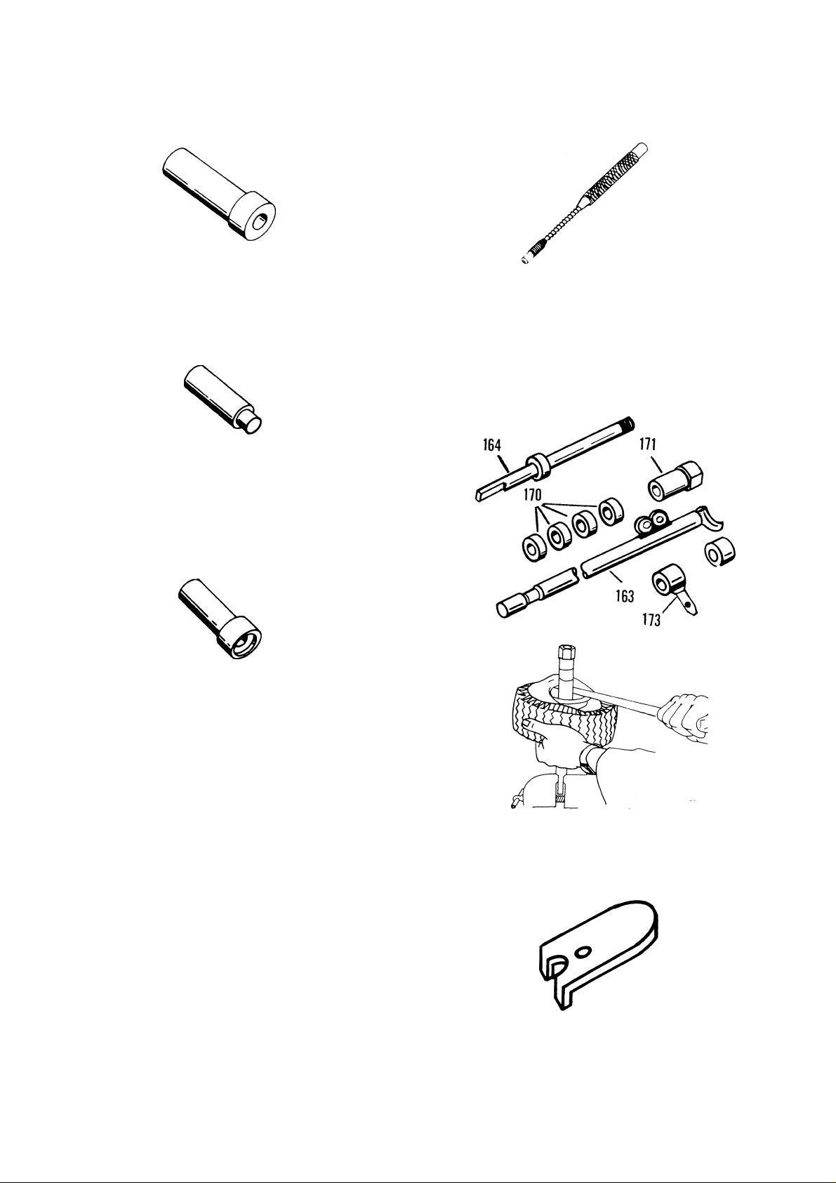
Special Tools
000078 - Bearing Driver for SnoThro axle shaft and Sno-Thro gear
case.
000097 - Bearing Driver for SnoThro gear case flange and blower
bearing supports.
Roll Pin Driver for installation of
roll pins on all Ariens equipment.
000096 - 1/8
000162-3/16
000099-5/16
000098 - 1-1/4
000131 - Bearing Cup Driver for
Sno-Thro gear case. Slide Driver.
(£
000246 - Spring Tool. For most
Ariens Springs.
5)
000200 - Tire Removal and Re
placement Tool for small pneuma
tic tires.
000090 - Bearing Adjusting Wrench
for Sno-Thro gear case adjustment
plug.
IV
Page 5

Index
Section
Specifications.
Handlebars and Controls.
Speed Selector and Wheels
Belt Drive
Reduction Drive
Friction Wheel Drive.
Auger/Impeller.
Gear Case.
Engine and Headlight
Attachments..............
© Ariens 1987
RM-924
Part No. 000123A
Printed in U.S.A. 8/87
Page 6

Notes
Page 7

Specifications
Length.................................................................... 60-63 inches
Height....................................................................40"
Cleaning Width
Shipping Weight................................................... 245 lbs to 345 lbs.
Wheel Size.............................................................(4.80/4.00 x 8) (16/6.50 x 8) (4.10/3.50 x 6)
Engine, Horsepower
Fuel........................................................................Unleaded - 1 Gallon Tanks
Governed R.P.M
Impeller R.P.M
Discharge Distance..............................................3' - 30'
Air Cleaner
Engine Oil
Spark Plug and Gap.................................................030 Champion RJ-17LM
Friction Wheel Drive
Differential.............................................................Standard or Available
.....................................................
............................................
...................................................
......................................................
............................................................
.............................................................
............................................
24"-36"
7-11 H.P.
• 3600
1080
Required with Summer Attachment
10W30, 5W30
Yes
Forward Speed
Reverse Speed
Electric Start Available
Headlight Available..............................................Yes
.....................................................
.....................................................
........................................
5 Forward .80 to 2.8 MPH
1 Reverse - 1 MPH
Yes - Available On All Models
1-1
Page 8

Handlebars and Controls
Table of Contents
Page
2.1 Upper Handlebar Panel and Key Switch...............................................................................................2-4
2.2 Lower Handlebar.......................................................................................................................................2-4
2.3 Clutch Handle.............................................................................................................................................2-5
2.4 Attachment Clutch Adjustment............................................................................................................ 2-5
2.5 Wheel Drive Clutch Lever and Traction Rod........................................................................................2-5
2.6 Clutch Yoke and Fork...............................................................................................................................2-6
2.7 Traction Drive Clutch Adjustment..........................................................................................................2-6
2.8 Mechanical interlock Adjustment...........................................................................................................2-7
2.9 Bellcrank and Slider..................................................................................................................................2-7
2.10 Chute Crank.............................................................................................................................................2-8
2.11 Electrical Interlock Adjustment..........................................................................................................2-10
List of Illustrations
Page
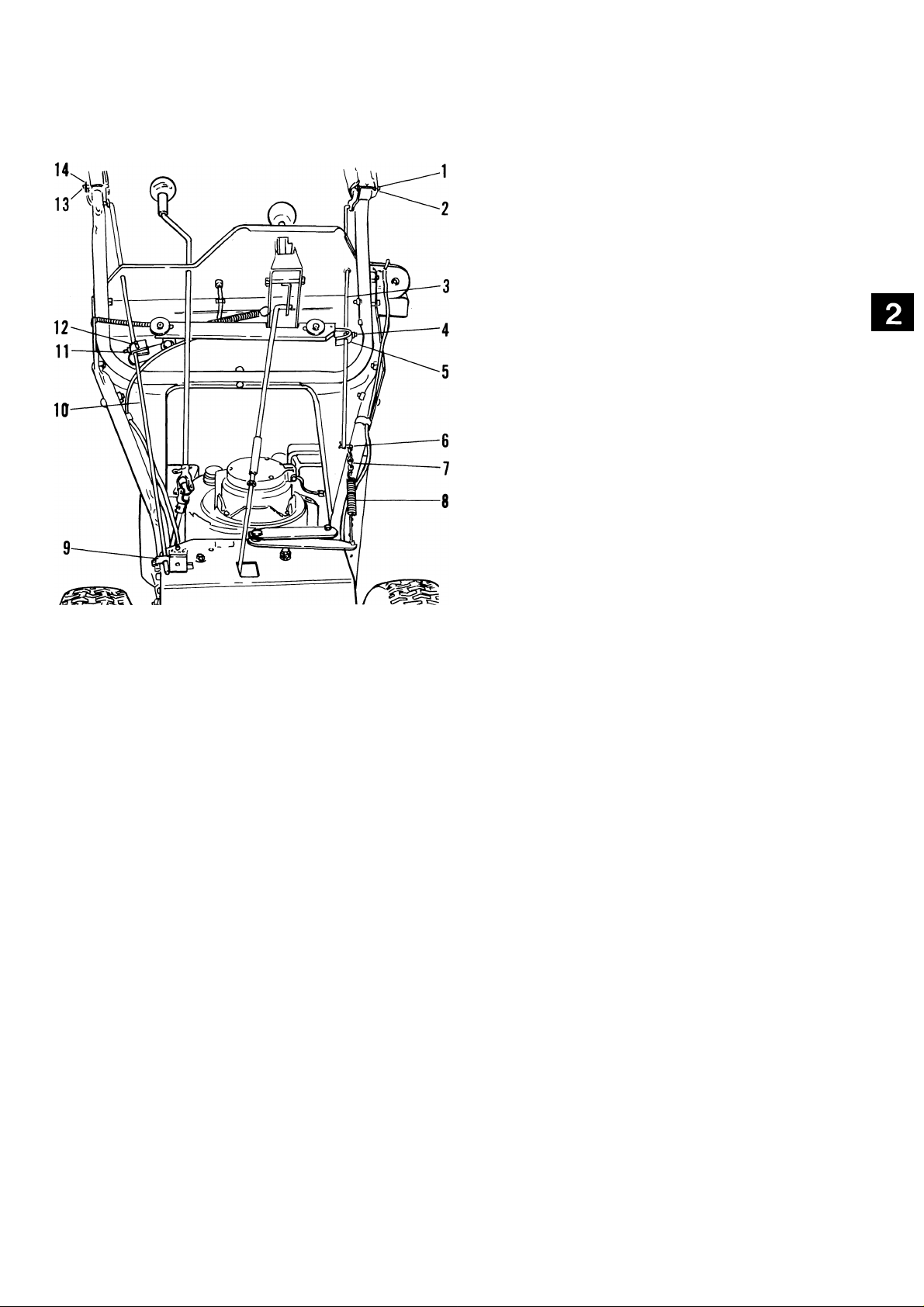
2-1: Handlebars and Controls..........................................................................................................................2-1
2-2: Handlebars and Controls Exploded View..............................................................................................2-2
2-3: Handlebar Assembly..................................................................................................................................2-4
2-4: Attachment Clutch and Traction Rod..................................................................................................... 2-5
2-5: Clutch Yoke and Fork Assembly............................................................................................................. 2-6
2-6: Traction Drive Clutch.................................................................................................................................2-6
2-7: Interlock........................................................................................................................................................2-7
2-8: Bellcrank and Slider...................................................................................................................................2-7
2-9: Chute Crank............................................................................................................................................... 2-8
2-10: Electrical Interlock....................................................................................................................................2-9
2-11: Electrical Interlock Adjustment............................................................................................................2-10
Page 9
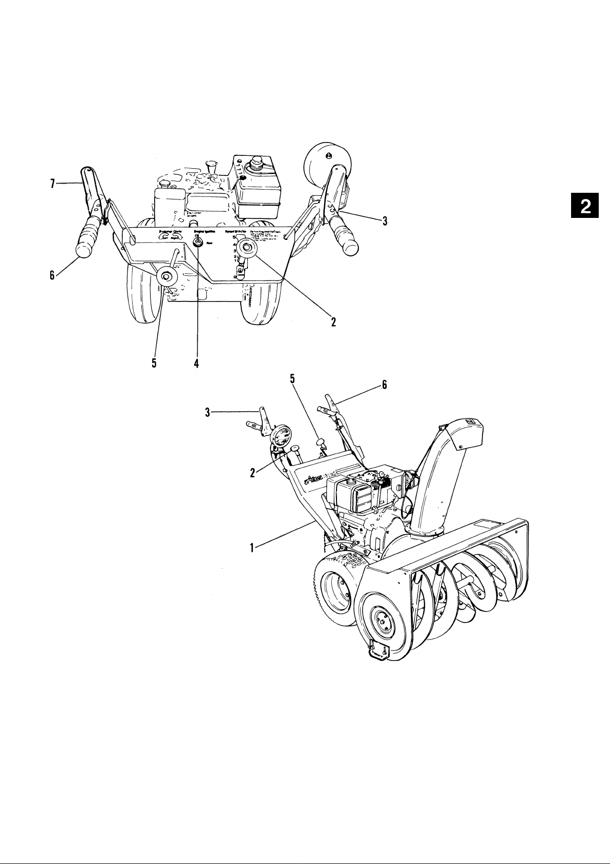
Handlebars and Controls
1. Lower Handlebar
2. Speed Control Lever
3. Attachment Clutch Handle
4. Key Switch
5. Chute Crank
6. Upper Handlebar
7. Wheel Drive Clutch Handle
Figure 2-1: Handlebars and Controls
2-1
Page 10
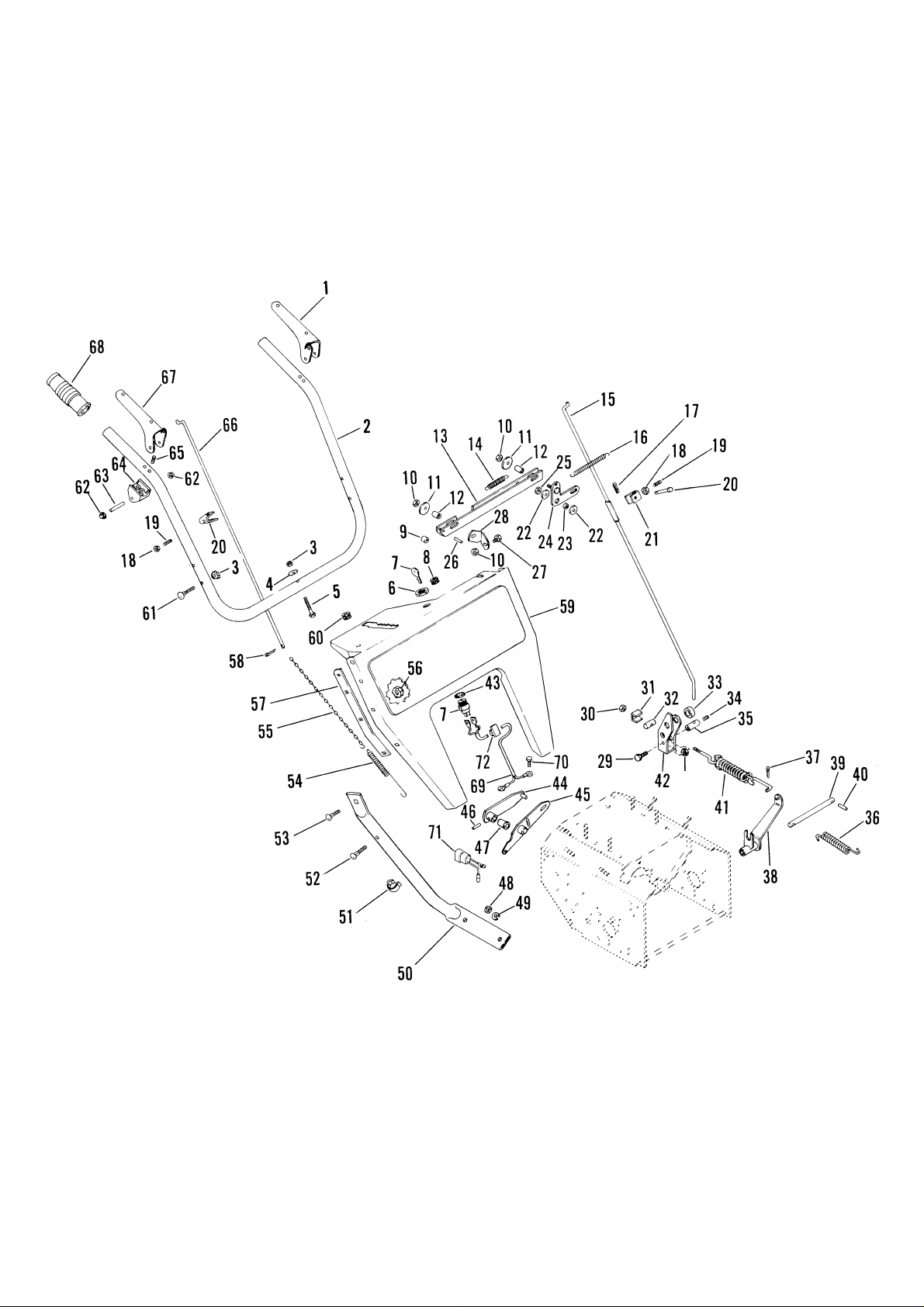
Handlebars And Controls
MECHANICAL INTERLOCK
Figure 2-2: Handlebars and Controls
2-2
Page 11

Handlebars And Controls
ITEM
NO.
1
2
3
4
5 Cap Screw 1/4-20 x 1-1/2
6 Key Switch Nut 5/8-32
7
8 Snap Bushing
9
10
11
12
13 Slider
14 Extension Spring
15 Traction Clutch Rod
16 Extension Spring
17
18
19
20
21
22
23 Spacer Bushing
24 Bellcrank
25
26 Roll Pin 3/16x7/8
27
28
29
30
31
32
33
34
35
36
DESCRIPTION
Wheel Drive Clutch Lever
Upper Handle Bar
Lock Nut 1/4-20
Washer 1/4
Key Switch Assembly
Bushing
Lock Nut 1/4-20
Washer 9/32
Bushing
Hair Pin Int. 1/16 X 49/64
Jam Nut 1/4-20
Set Screw 1/4-20 x 3/4
Clevis Pin
Clevis
Washer 5/16
Lock Nut 5/16-18
Cap Screw 1/4-20 x 1/2
Stud Brace
Cap Screw 5/16-18 x 3/4
Lock Nut 5/16-18
Adapter Spacer
Adapter
Spacer
Set Screw 5/16-18 x 3/8
Rod Adapter
Extension Spring
ITEM
NO.
37
38
39
40
41
42
43
44
45
46
47
48
49
50
51
52
53
54
55
56
57
58
59
60
61
62
63
64
65
66
67
68
69
70
71
72
DESCRIPTION
Cotter Pin 3/32 X 3/4
Clutch Fork
Fork Pivot Rod
Cotter Pin 3/32 X 1"
Spring Assembly
Clutch Engagement Yoke
Lock Washer Int. 5/8
Lever
Lever
Roll Pin 5/32 X 7/8
Bushing
Nut 3/8-16
Lock Washer 3/8
R.H. Lower Handlebar
Clamp
Carriage Bolt 5/16-18 x 1-1/2
Carriage Bolt 5/16-18 x 3/4
Extension Spring
Clutch Chain
Lock Nut 5/16-18
L.H. Stiffener
Cotter Pin 1/8 X 1/2
Upper Handle Bar Panel
Snap Bushing
Carriage Bolt 1/4-20 x 1-1/2
Push Nut
Pin
Handle Pivot
Tapping Screw No. 12-14 x 1-1/2
Attachment Clutch Rod
Attachment Clutch Handle
Grip
Shorting Wire
Taptite 1/4-20 x 3/8
Jumper (924071)
Wire Clip
2-3
Page 12
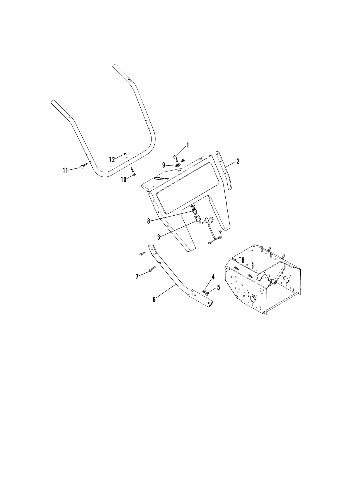
1. Key
2. Stiffener
3. Wire
4. Nut
5. Washer
6. Lower Handlebar
7. Carriage Bolt 5/16-18 x 1-1/2
8. Key Switch
9. Key Switch Nut
10. Cap Screw
11. Carriage Bolt 1/4-20 x 1-1/2
12. Lock Nut
Handlebars and Controls
Figure 2-3: Handlebar Assembly
2.1 Upper Handlebar Panel and Key Switch
Disconnect wires to key switch.
Remove key switch nut and remove key switch from
upper handlebar panel.
Remove (4) nuts and bolts on each side of handlebar
panel plus the bolt, nut and washer in center of
cross piece of upper handle bar and remove panel
stiffeners and upper handlebar.
Check parts for wear or replacement.
Assemble, using reverse procedure.
2.2 Lower Handlebar
Remove nut and washer attaching lower handlebar
to each side of frame and remove lower handlebar.
Check parts for wear or replacement.
Assemble, using reverse procedure.
2-4
Page 13
Handlebars and Controls
1. Push Nut
2. Pin
3. Attachment Clutch Rod
4. Setscrew
5. Clevis
6. Cotter Pin
7. Chain
8. Spring
9. Rod Adapter
10. Traction Clutch Rod
11. Setscrew
12. Clevis
13. Push Nut
14. Pin
Figure 2-4: Attachment Clutch and Traction Rod
2.3 Clutch Handle
Remove (2) push nuts, pin and (2) screws holding
Clutch Handle and pivot to upper handle bar and
remove pivot and disconnect Clutch Handle from
clutch rod.
Remove set screw, jam nut and clevis from clutch
rod.
Remove cotter pin connecting rod to chain and
remove rod.
Disconnect chain and clutch spring from lever.
Check parts for wear or replacement.
Assemble, using reverse procedure.
2.4 Attachment Clutch Adjustment
Attachment Clutch is adjusted by connecting chain
to spring just below attachment clutch rod. Connect
spring to a chain link so chain is snug but so attach
ment idler drops away from belt with lever all the
way up.
2.5 Wheel Drive Clutch Lever and Traction Rod
Remove (2) push nuts, pin and (2) screws holding
pivot and Wheel Drive Clutch Lever to upper handle
bar and remove pivot and Wheel Drive Clutch Lever.
Remove set screw, nut, hair pin and clevis pin
holding clevis to Traction Clutch Rod.
Remove set screw in rod adapter and remove Trac
tion Clutch Rod.
Check parts for wear or replacement.
Assemble, using reverse procedure.
2-5
Page 14
Handelbars and Controls
2.6 Clutch Yoke and Fork
Remove locknut and adapter spacer holding spring
assembly in clutch yoke.
Remove capscrew, nut and rod adapter from yoke.
Remove cotter pin from end of spring assembly
in clutch fork and remove spring assembly and
extension spring.
2.7 Traction Drive Clutch Adjustment
WARNING: Gasoline is highly flammable
A
A
and its vapors are explosive. Handle with
care. Never allow smoking materials, sparks
or flame (match, pilot light, etc.) near
equipment or fuel container.
CAUTION: When unit is tipped up onto
housing remove enough fuel so that no
spillage will occur.
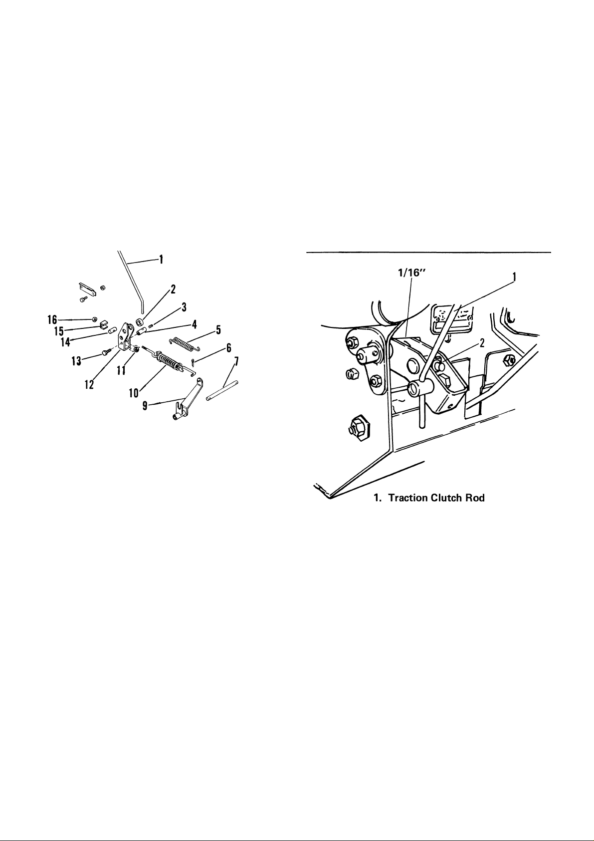
Traction Clutch Rod
1.
2. Spacer
3. Setscrew
Rod Adapter
4.
Extension Spring
5.
Cotter Pin
6.
Fork Pivot Rod
7.
Cotter Pin
8.
Figure 2-5: Clutch Yoke and Fork Assembly
Punch out roll pins holding fork pivot rod in frame
and remove rod and clutch fork.
Check parts for wear or replacement.
Assemble, using reverse procedure.
9. Clutch Fork
10. Spring Assembly
11. Nut
12. Clutch Yoke
13. Capscrew
14. Adapter
15. Adapter Spacer
16. Lock Nut
2. Adjustment Nut
Figure 2-6: Traction Drive Clutch
Adjust traction clutch to compensate for wear of
friction wheel when slippage occurs.
To adjust traction clutch, place speed selector in
First (1) and tip machine forward onto housing.
With traction clutch disengaged turn wheels while
tightening adjustment nut, at clutch yoke, until
wheels begin to drag. Engage and release traction
clutch to align clutch linkage. Repeat procedure as
necessary. When wheel drag is obtained with linkage
aligned, turn nut back three turns. Wheels will then
turn freely.
2-6
Page 15
Handelbars and Controls
2.8 Mechanical Interlock Adjustment
WARNING: With improper usage of unit,
failure of interlock if unnoticed, could
A
result in severe personal injury.
Check interlock by pressing down on clutch levers
(engaging both clutches). Remove hand from
attachment clutch lever, attachment clutch should
remain engaged until traction clutch lever is re
leased then both clutches must disengage.
2.9 Bellcrank and Slider
Remove nut and washer holding bellcrank to upper
handlebar panel.
Remove nut and washer holding slider to upper
handlebar panel and disconnect spring from upper
panel.
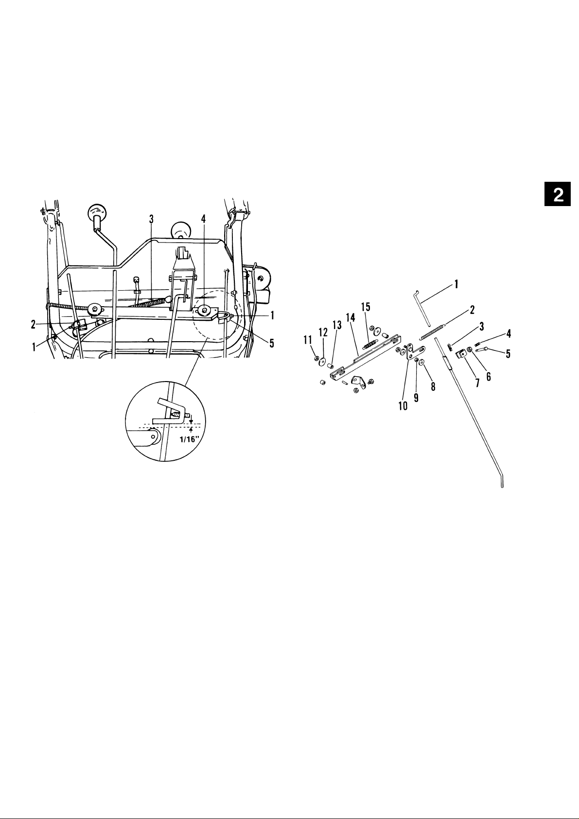
1.
Setscrew
Traction Clutch Clevis
2.
Slider
3.
4. Roller
5. Attachment Clutch Clevis
Figure 2-7: Interlock
With traction clutch lever "UP" (disengaged) loosen
clevis set screw on traction clutch rod, pull clevis
down until slider is at end of slot and tighten set
screw.
Engage both clutch levers "DOWN", loosen clevis
set screw on attachment clutch rod and slide clevis
to clear roller on slider by 1/16 inch. Tighten set
screw with leg of clevis parallel to slider.
1. Attachment Clutch Rod 9.
2. Extension Spring
3. Hair Pin
4. Setscrew
5. Clevis Pin
6. Jam Nut 14.
7. Clevis
8. Washer
Figure 2-8:
Bellcrank and Slider
Spacer Bushing
10.
Bellcrank
Lock Nut
11.
12.
Washer
13.
Bushing
Slider
15.
Extension Spring
Remove slider assembly and check all parts for
replacement or repair.
NOTE: Be sure to check bushings and spacers for
wear.
Assemble, using reverse procedure.
2-7
Page 16
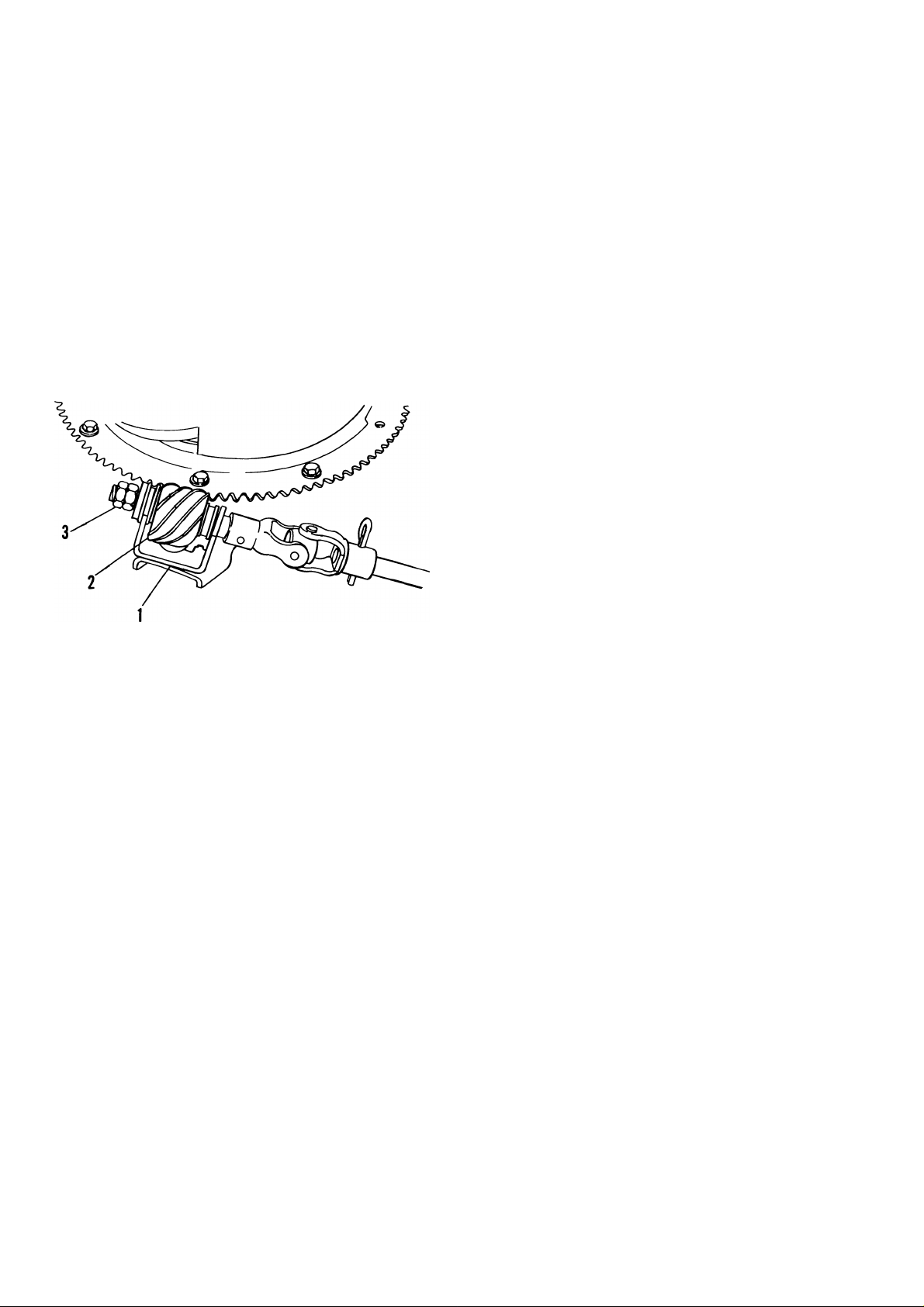
2.10 Chute Crank
Handelbars and Controls
Smooth and easy rotation of properly lubricated
chute with crank (without binding) is obtained by
adjusting clearance between worm and discharge
chute gear teeth. To adjust, loosen nut on bracket
supporting worm, position worm to fully engage
(without binding), gear teeth on discharge chute
and tighten nut.
On ST 1136 to prevent discharge chute from rotat
ing by itself when unit is being operated, tighten jam
nuts on end of crank rod to put increased tension on
worm gear.
1. Bracket
2. Worm Gear
3. Adjustment Nuts
Figure 2-9: Chute Crank
2-8
Page 17
WHITE
TO ENGINE ■
MAGNETO
Handlebars and Controls
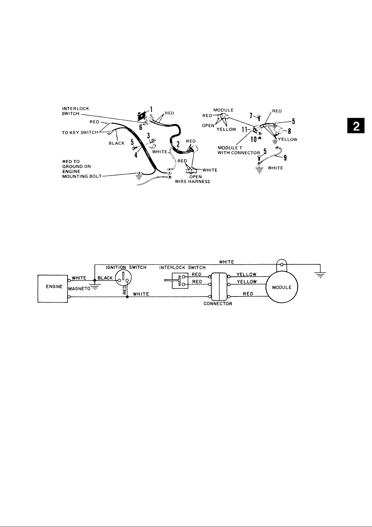
ELECTRICAL INTERLOCK
1. Switch Boot
2. Wiring Harness
3. Clip
4. Shorting Wire
5. Flange Whiziock Screw
6. Switch
7. Cap Screw 10-24 x 3/8
8. Modulet
9. Wire Ground
10. Keps Nut
11. Connector
Figure 2-10: Electrical Interlock
2-9
Page 18
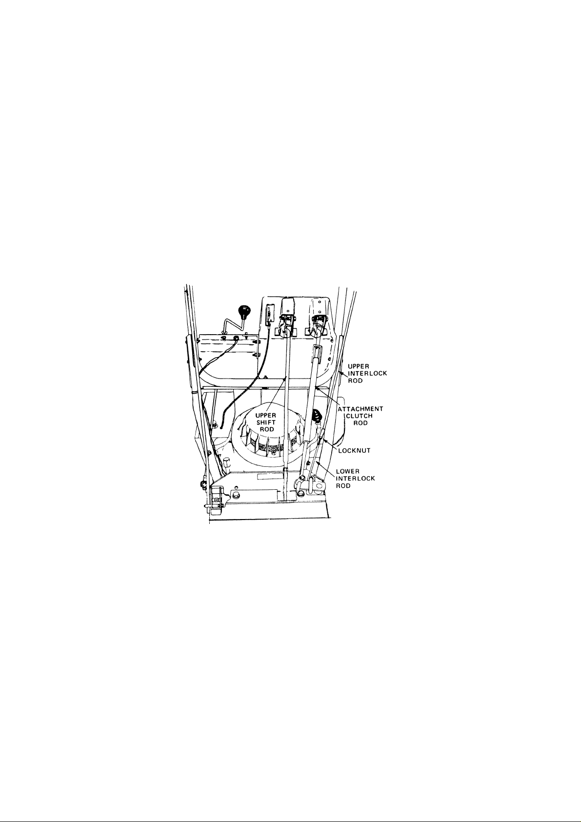
Handlebars and Controls
2.11 Electrical Interlock Adjustment
Engine runs with interlock and/or traction clutch
engaged. Engine must stop if both are disengaged
with attachment clutch engaged.
Shorten interlock rod if engine will not run with
interlock, attachment clutch and/or traction clutch
engaged. Lengthen interlock rod if engine stays
running when both interlock and traction handle are
released with attachment clutch disengaged.
Check switch bracket alignment with switch and
align if necessary.
To adjust length of rod, remove cotter pin from
upper interlock rod at handle, loosen lock nut and
turn rod to lengthen or shorten.
Figure 2-11: Electrical Interlock
2-10
Page 19

Notes
Page 20

Speed Selector and Wheels
Table of Contents
Page
3.1 Speed Selector...........................................................................................................................................3-4
3.2 Speed Selector Adjustment.....................................................................................................................3-4
3.3 Shift Arm Lever and Links.......................................................................................................................3-4
3.4 Wheel Assembly.........................................................................................................................................3-4
List of Illustrations
Page
3-1: Speed Selector and Wheels......................................................................................................................3-1
3-2: Speed Selector and Wheels Exploded View..........................................................................................3-2
3-3: Speed Selector............................................................................................................................................3-4
Page 21
Speed Selector and Wheels
f—
V—a__rt__a--'
1. Speed Selector
2. Upper Shift Rod
3. Nut
4. Lower Shift Rod
j—If—\J—
i
5. Shift Links
6. Shift Links
7. Shift Arm Lever
8. Shift Lever Bracket
Figure 3-1: Speed Selector and Wheels
3-1
Page 22

Speed Selector And Wheels
©-
3-2
Page 23

Speed Selector And Wheels
ITE M
NO .
1
2
3
4
5
6
7
8
9
10
11 Upper Shift Rod
12 Nut 5/16-24
13 Cotter Pin 3/32 X 3/4
14 Shift Link
15
DE SC R IP TI ON
Snap Ring Ext. 1/2
Knob
Rod 18
Extension Spring
Pivot
Lock Nut 5/16-18
Lock Nut 1/4-20
Cap Screw 1/4-20 X 1"
Cap Screw 5/16-18 x 2-1/2
Cotter Pin 1/8 X 3/4
Clevis Pin
ITE M
NO .
16
17
19
20
21
22
23
24
25
26
27 Taptite 5/16-18 X 1/2
28
29
DE SC R IP TI ON
Lower Shift Rod
Shift Arm Lever
Frame
Bottom Cover
Spindle Cup
Push Nut or Cotter Pin
Wheel Assembly
Hub Cap
Taptite 1/2-20 x 5/8
Cap Screw 5/16-18 x 1/2
Shift Lever Bracket
Cap Screw 5/16-18 x 3"
Spacer
3-3
Page 24

Speed Selector and Wheels
3.1 Speed Selector
Remove cotter pin in upper rod and disconnect
rod from pivot.
Remove cotter in lower rod and disconnect from
shift arm lever.
Remove upper cap screw and nut in pivot and
remove shift rod and knob.
Remove lower cap screw and nut in pivot and
remove pivot from upper handle bar panel.
Check parts for wear or replacement.
Assemble, using reverse procedure.
3.2 Speed Selector Adjustment
Place Speed Selector in Reverse (R) position. While
pulling lower rod up to its maximum up position,
turn upper shift rod into lower rod until end of
upper rod lines up with hole in shift handle. Insert
upper rod into shift handle, install cotter pin and
tighten lock nut on shift rod.
3.3 Shift Arm Lever and Links
Remove cotter pin and clevis pin holding shift links
to shift arm lever.
Remove (3) capscrews, on outside of frame, holding
shift lever bracket to frame and remove bracket.
Remove capscrews, nut and spacer from shift arm
lever and disconnect lever from shift lever bracket.
Check parts for wear or replacement.
Assemble, using reverse procedure.
ggsl
isssi
- j
1. Lock Nut
2. Cotter Pin
3. Upper Shift Rod
4. Lower Shift Rod
5. Capscrew
6. Speed Selector Knob and Rod
Figure 3-3: Speed Selector
3.4 Wheel Assembly
Remove hub cap, push nut and spindle cap.
Remove (3) bolts holding wheel to wheel hub and
remove wheel.
Check parts for wear or replacement.
Assemble, using reverse procedure.
3-4
Page 25

Notes
Page 26

Belt Drive
Table of Contents
Page
4.1 Introduction.............................................................................................................................................. 4-4
4.2 Attachment Drive Belt...............................................................................................................................4-4
4.3 Traction Drive Belt.....................................................................................................................................4-4
List of Illustrations
Page
4-1: Belt Drive Assembly...................................................................................................................................4-1
4-2: Belt Drive Exploded View..........................................................................................................................4-2
4-3: Drive Belts....................................................................................................................................................4-4
4-4: Impeller Brake..............................................................................................................................................4-4
Page 27

Belt Drive
1. Pulley
2. Attachment Pulley
3. Idler
4. Belt
5. Engine Pulley
6. Belt
Figure 4-1: Belt Drive Assembly
4-1
Page 28

Belt Drive
4-2
Page 29

Belt Drive
ITE M
NO .
9
10
11
12
13
14
15
16 Set Screw 5/16-18 x 3/8 38
17
18
19 Pulley
20
21 V-Belt
22 Rib Neck Bolt 5/16-18x7/8
23 Pulley
24
25
26 Lock Nut 1/4-20
27 V-Belt
28 Hub
29
30
DE SC R IP TI ON
Taptite 1/4-20 x 1/2
Washer 17/64
Belt Cover 33
Belt Finger
Washer 3/8
Lock Washer Ext. 5/16
Cap Screw 5/16-24 x 3/4
Pulley
Straight Key 1/4 x 1-3/4 x 1/4
Lock Nut 5/8-18
Belt Retainer
Cap Screw 1/4-20 x 1/2
Lock Nut 5/16-18
Lock Nut 5/16-18
ITE M
NO .
31
32
34
35
36
37 Bracket
39
40
41 Taptite No. 10-24 x 3/8
42
43
44
45
46
47
48
49
50
51
52
DE SC R IP TI ON
Washer 5/16
Idler
Bearing Spacer
Cap Screw 5/16-18 x 1-1/4
Idler Arm
Clevis Pin
Taptite 1/4-20 x 3/8
Cotter Pin 3/32 X 3/4
Return Clip
Activating Shaft
Extension Spring 3-3/8
Bushing
Spacer
Idler Arm
Extension Spring
Cotter Pin 1/8 x 1"
Washer 3/8
Wave Washer
R.H. Support
L.H. Support
4-3
Page 30

Belt Drive
4.1 Introduction
WARNING: Remove wire from spark plug
before attempting any repair or adjustment
A
When unit is tipped to preform the service proce
dures in this section, remove enough fuel so that no
spillage will occur, block securely and remove bot
tom cover.
A
Separate auger/impeller housing per instructions in
Auger/Impeller Section.
4.2 Attachment Drive Belt
procedures.
WARNING: Gasoline is highly flammable
and its vapors are explosive. Handle with
care.
Remove attachment drive belt from pulley (hold
brake away from belt).
Replace attachment drive belt in reverse order
making sure pulleys align. If alignment is necessary,
loosen attachment pulley set screws, reposition
pulley and retighten set screws.
WARNING: When clutch is engaged, impel
ler brake disengages. If brake is not 1/16 to
A
1/8" from belt when disengaged
1. Traction Drive Belt
2. Engine Pulley
3. Attachment Drive Belt
4. Attachment Belt Idler
5. Traction Belt Idler
Figure 4-3: Drive Belts
1. Brake Shoe
2. Drive Belt
Figure 4-4: Impeller Brake
4.3 Traction Drive Belt
Pull idler away from belt and remove belt from idler
pulley, engine and driven pulley (it may be neces
sary to turn engine engine pulley using rewind
starter).
NOTE: To gain clearance engage traction clutch and
if necessary pull back attachment idler arm clevis
pin.
Replace traction drive belt in reverse order making
sure pulleys align. If alignment is necessary, loosen
engine pulley set screws, reposition pulley and re
tighten set screws. Check alignment of attachment
driven pulley and align if necessary.
4-4
i
Page 31

Notes
Page 32

Reduction Drive
Table of Contents
Page
5.1 Introduction................................................................................................................................................5-4
5.2 Differential, Lockout and Axle................................................................................................................5-4
5.3 Axle Bearings.............................................................................................................................................5-4
5.4 Pinion, Shaft and Sprocket......................................................................................................................5-4
5.5 Reduction Shaft.........................................................................................................................................5-4
5.6 Hex Shaft.....................................................................................................................................................5-4
5.7 Drive Chains...............................................................................................................................................5-5
5.8 Drive Chain Adjustment...........................................................................................................................5-5
List of Illustrations
Page
5-1: Reduction Drive Assembly.......................................................................................................................5-1
5-2: Reduction Drive Exploded View...............................................................................................................5-2
5-3: Drive Chains.................................................................................................................................................5-5
Page 33

Reduction Drive
Figure 5-1: Reduction Drive Assembly
1. Idler Chain
2. Hex Shaft
3. Pinion Shaft
4. Drive Spindle Housing
5. Spindle
6. Differential
7. Differential Lockout
8. Axle
9. Pinion and Sprocket
10. Sprocket
11. Pinion Chain
5-1
Page 34

Reduction Drive
5-2
Figure 5-2: Reduction Drive
Page 35

Reduction Drive
ITE M
NO .
1
2
3
4
5
6
7
8
9
10 9 Tooth Sprocket
11
12
13
14
15
16
17
18
19
20
21 Reduction Shaft
22
23
24
25
26
27
28
29 Roll Pin 1/8 X 1"
30
DE SC R IP TI ON
Taptite 1/4-20 x 3/8
Shaft Support
Bearing Retainer
Ball Bearing 1-1/8 I.D.
Washer 7/8
Rib Neck Bolt 1/4-20 x 1/2
Lock Nut 1/4-20
Hex Shaft
Woodruff Key 1/8 x 5/8 x 1/4
Idler Chain
Washer 17/32
Bearing Flange
Ball Bearing 1/2 I.D.
Bearing Flange
Lock Nut No. 10-24
Lock Nut 1/2-20
Nut 3/8-16
Lock Washer 3/8
Washer 3/8
Bushing
Reduction Sprocket (Double or Single)
Shaft Support
Taptite 1/4-20 x 1/2
Washer 5/8
Pinion Shaft
Roll Pin 5/32x1"
Pinion Chain
ITE M
NO .
31
32
33
34
35
36
37 Lock Washer Ext. 1/4
38
39 Bushing
40
41
42 Roll Pin 3/32 X 1"
43
44
45 Compression Spring
46
47
48
49
50
51
52
53
54
55
DE SC R IP TI ON
Pinion and Sprocket
Bushing
Zerk Fitting
Differential or Spur Gear
L.H. Axle
Bushing
Zerk Fitting
Groove Pin 1/4 X 1-3/4
Lockout Hub Assembly
Knob
Lockout Hub
Pin
Wheel Hub
Washer 3/4
Roll Pin 3/16 X 1-1/4
Cotter Pin 1/8 X 1-1/4
Feather Key 3/16 x 1-1/4 x 3/16
Axle Shaft
Woodruff Key 1/4x3/4x5/16
Roll Pin 3/16 X 1-1/2
R.H. Axle
5-3
Page 36

Reduction Drive
5.1 Introduction
WARNING: Gasoline is highly flammable
and its vapors are explosive. Handle with
A
When unit is tipped to preform the service proce
dures in this section, remove enough fuel so that
no spillage will occur, block securely and remove
bottom cover.
A
5.2 Differential, Lockout and Axle
Remove groove pin that secures lockout assembly
to left hand axle and lockout assembly from shaft.
(Pin is tapered and must be driven from small
end.)
care.
WARNING: Remove wire from spark plug
before attempting any repair or adjust
ment procedures.
Remove cap screws and lock nuts that retain
bearing retainer and bearing on frame.
Assemble in reverse order.
5.4 Pinion, Shaft and Sprocket
Remove L.H. rear wheel per instructions in Speed
Selector and Wheels Section.
Remove the roll pins from pinion shaft. Note
position of washers and remove shaft from frame.
Check pinion and sprocket bushings as well as
other parts for wear or damage and replace as
necessary.
Assemble in reverse order.
5.5 Reduction Shaft
Remove nuts and lock washers from ends of reduc
tion shaft.
Remove shaft and reduction sprocket from unit.
Remove roll pin that secures knob, spring and pin
to lockout hub.
Remove L.H. axle from unit.
Remove roll pin from R.H. axle, then remove
differential from axle while sliding axle from unit.
(Differential is serviced as a complete assembly.)
Check L.H. axle bushings and other parts for wear
or damage and replace as necessary.
Assemble in reverse order.
On units with spur gear, to remove axle, remove
cotter pins that secure wheel hubs to axle, roll pins
from axle and parts from unit.
Check components for wear or damage and replace
as needed.
Assemble in reverse order.
5.3 Axle Bearings
Check reduction sprocket bushings and other parts
for wear or damage and replace as necessary.
Assemble in reverse order and adjust chain per
instructions in Drive Chain Adjustment.
5.6 Hex Shaft
Hold hex shaft on sprocket end with a wrench and
remove lock nut at outside of frame. Slide hex
shaft to center of frame until it clears sprocket and
remove 9 tooth sprocket.
To service hex shaft ball bearing, remove four lock
nuts from bearing flanges then flanges and bearing
from unit.
Check parts for wear or damage and replace as
necessary.
Assemble in reverse order being sure that washers
are in position at outside of bearing flanges.
To replace axle bearings, remove axles per above
instructions.
5-4
Page 37

Reduction Drive
5.7 Drive Chains
Remove link from chain and chain from sprocket.
On continuous chain grind off end of rivet.
When replacing chain, be sure retainer clip faces
center of unit and is well seated in grooves of master
link, No. 000041.
5.8 Drive Chain Adjustment
If Sno-Thro is difficult to push because of tight or
interfering drive chains, proceed as follows:
Stand unit up on auger/impeller housing and re
move bottom cover.
Chain tension is adjusted by loosening two nuts on
Reduction Shaft. Adjust reduction sprocket up or
down in slot to obtain proper tension (chain
should be snug). Retighten both nuts. Torque to
170-180 inch lbs.
Chain interference with the Bearing Flange on Hex
Shaft can occur if there is no Washer between
Sprocket and Bearing. Make sure washer is installed.
NOTE: Check interlock mechanism to ensure pro
per operation as follows:
Check both clutches to be sure they operate freely
without binding.
Figure 5-3: Drive Chains
5-5
Page 38

Friction Wheel Drive
Table of Contents
Page
6.1 Introduction........................................................................................................................6-3
6.2 Friction Wheel....................................................................................................................6-3
6.3 Friction Wheel Carrier.......................................................................................................6-3
6.4 Drive Plate Spindle.............................................................................................................6-3
List of Illustrations
Page
6-1: Friction Wheel Assembly.................................................................................................. 6-1
6-2: Friction Wheel Exploded View..........................................................................................6-2
6-3: Friction Wheel.....................................................................................................................6-3
Page 39

Friction Wheei Drive
1. Hex Shaft
2. Friction Disc
3. Drive Plate
4. Drive Spindle Housing
Figure 6-1: Friction Wheel Assembly
6-1
Page 40

Friction Wheel Drive
iTEM
NO.
1
2 Drive Disc Spacer
3
4
5
6
7
8
9
10
11
12
13
14
15
DESCRIPTION
Drive Plate
Spindle 18
Woodruff Key 1/8 x 1/2 x 13/64
Drive Spindle Housing
Bearing 5/8 I.D.
Bearing Spacer
Bearing Housing
Roller 24
Washer 11/32
Lock Washer 5/16
Cap Screw 5/16-18 X 1"
Shaft Support 28
Taptite 1/4-20 x 3/8
Carrier Shaft
6-2
ITEM
NO.
16
17
19
20
21
22
23
25
26
27 Spindle Hub
29
30
31
DESCRIPTION
Roll Pin 5/32 X 1"
Bushing
Nylon Lock Nut 7/8-14
Bushing
Carrier
Radial Bearing 7/8
Washer 7/8
Snap Ring Int. 1-3/4
Hub
Friction Wheel
Taptite 5/16-18 X 1/2
Cap Screw 5/16-18 x 1/2
Lock Washer 5/16
Pulley
Lock Nut
Page 41

Friction Wheel Drive
6.1 Introduction
WARNING: Remove wire from spark plug
before attempting any repair or adjustment
A
When unit is tipped to preform the service proce
dures in this section, remove enough fuel so that
no spillage will occur, block securely and remove
bottom cover.
A
6.2 Friction Wheel
Remove bottom cover by removing four cap screws.
Place Speed Selector in first "1" position, depress
Traction Clutch Lever to hold friction wheel and
loosen five cap screws securing friction wheel to
hub. Release traction clutch lever, remove cap
screws, shift to third "3" position, disconnect
shift link and remove friction wheel.
procedures.
WARNING: Gasoline is highly flammable
and its vapors are explosive. Handle with
care.
6.3 Friction Wheel Carrier
Remove roll pins from carrier shaft and pull shaft
out of frame far enough to free carrier.
Hold hex shaft on sprocket end with a wrench and
remove lock nut at outside of frame. Slide hex
shaft to center of frame until it clears sprocket and
remove carrier from frame.
Remove nylon lock nut from spindle hub and hub
from carrier.
Remove snap ring, washer, bearing and bushing from
carrier.
Check carrier bushings and other parts for wear or
damage and replace as necessary.
Assemble in reverse order.
6.4 Drive Plate Spindle
Separate auger/impeller housing per instructions in
Auger/Impeller Section.
Remove lock nut from pulley end of spindle and
pulley from spindle. (To remove nut, engage friction
wheel drive to keep spindle from turning.)
Secure new friction wheel on hub with five cap
screws and torque cap screws to 8-10 foot pounds.
Install shift link.
1. Cap Screw
2. Friction Wheel
Remove friction wheel carrier per previous instruc
tions.
Remove drive spindle housing from frame by re
moving three cap screws and lock washers from
housing.
Check spindle bearings and other parts for wear or
damage and replace as necessary.
Assemble in reverse order applying Locktite Anti
seize to outside of bearing housing.
NOTE: Mix 1 part Mobil 1 with 16 parts Locktite
No. 767 Antiseize.
Figure 6-3: Friction Wheel
6-3
Page 42

Auger/Impeller
Table of Contents
Page
7.1 Introduction....................................................................................................................... 7-4
7.2 Auger/Impeller Housing....................................................................................................7-4
7.3 Auger/Impeller Removal...................................................................................................7-4
7.4 Attachment Clutch/Impeller Brake
7.5 Discharge Chute................................................................................................................7-5
7.6 Deflector.............................................................................................................................7-5
7.7 Scraper Blade.................................................................................................................. 7-6
7.8 Shear Bolt Replacement...................................................................................................7-6
7.9 Runners..............................................................................................................................7-6
..................................................................................
7-4
List of Illustrations
Page
7-1: Auger/Impeller Assembly..........................................................................................7-1
7-2: Auger/Impeller Exploded View..................................................................................7-2
7-3: Impeller Brake.............................................................................................................7-4
7-4: Discharge Chute....................................................................................................... 7-5
7-5: Deflector......................................................................................................................7-5
7-6: Scraper Blade..............................................................................................................7-6
7-7: Runners.......................................................................................................................7-6
Page 43

Auger/Impeller
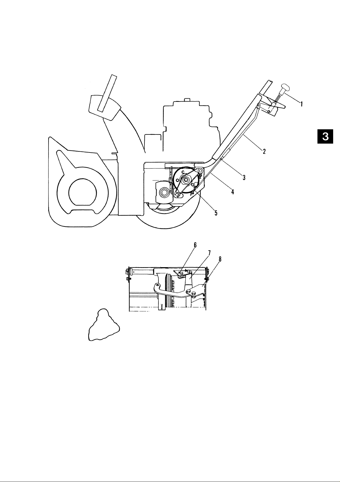
1. Chute Crank
2. Universal Joint
3. Impeller
4. Gear Case
5. Scraper Blade
Figure 7-1: Auger/Impeller Assembly
6. Runner
7. Auger Housing
8. Auger
9. Discharge Chute
10. Worm Gear
7-1
Page 44

Auger/Impeller
¿^>,3
7-2
Figure 7-2: Auger/Impeller
Page 45

Auger/Impeller
ITEM
NO.
1 Deflector 36
2
3
4
5
6 Universal Joint
7
8 Rod
9
10
11
12
13
14
15
16
17
18
19
20 Runner 55
21
22 Lock Nut 3/8-16
23
24
25 Radial Bearing 3/4 or Ball Bearing
26 Bearing Flange
27
28
29
30 Lock Nut 5/16-18 65
31 Zerk Fitting
32 Auger
33
34
35 Bearing Support
36
DESCRIPTION
Cap
Knob 38
Chute Control Crank
Hair Pin or Cotter Pin
Roll Pin 1/8 X 3/4
Chute Crank Bracket
Worm Shaft
Wave Washer
L.H. Worm Gear 47
Washer 25/64 - Plastic
Carriage Bolt 5/16-18 x 3/4 49
Worm Clevis
Lock Washer 3/8
Lock Washer 5/16
Nut 5/16-18
Auger/Impeller Housing
Washer 3/8
Carriage Bolt 3/8-16 x 1"
Carraige Bolt 3/8-16 x 3/4
V
Rib Neck Bolt 1/4-20 x 1/2
Scraper Blade
Carriage Bolt 5/16-18 x 5/8
Shear Boltw/Nut
Washer 1"
ITEM
NO.
37
39
40
41
42
43
44
45
46
48
50
51
52
53
54
56
57
58
59
60
61
62
63
64
66
67
68
69
70
DESCRIPTION
Lock Nut 1/4-20
Bushing
Washer 1/2
Lock Washer 1/2
Cap Screw 1/2-13 x 1"
Extension Spring
Lock Nut 1/4-20
Arm Extension
Arm w/Lining
Clevis Pin
Cotter Pin 1/16 X 3/4
Brake Lining
Oval Rivet 3/16 x 7/16
Cap Screw 1/4-20 x 5/8
Nut Retainer 3/8-16
Flanged Screw 3/8-16 x 3/4
Bearing Flange
Taptite No. 10-24 x 3/8
Chute Clamp
Cotter Pin 3/32 X 3/4
Control Cable
Machine Screw No. 10-32 x 1/2
Tee Handle
Deflector Control Bracket
Discharge Chute
Lock Nut 3/8-16
Washer 13/32
Plastic Washer
Cap Screw 3/8-16 x 3/4
Rib Neck Bolt 5/16x7/16
Pulley
Hub
Set Screw 5/16-18 x 3/8
Nut 5/16-18
Impeller and Gear Case
7-3
Page 46

Auger/Impeller
7.1 Introduction
WARNING: Remove wire from spark plug
before attempting any repair or adjustment
A
When unit is tipped to preform the service proce
dures in this section, remove enough fuel so that no
spillage will occur, block securely and remove bot
tom cover.
A
7.2 Auger/Impeller Housing
To separate housing from unit, remove two screws
securing belt guard to unit and remove belt guard.
Remove hairpin from chute crank assembly at "U"
joint and separate.
Remove attachment drive belt from engine pulley
(it may be necessary to turn engine pulley using
rewind starter).
procedures.
WARNING: Gasoline is highly flammable
and its vapors are explosive. Handle with
care.
Grasp auger assembly and pull gear case and auger/
impeller assembly free of housing.
Drive roll pin out of shaft ends, remove shear bolts
and remove auger from shaft.
Check all parts for wear or replacement.
Assemble using reverse procedure.
7.4 Attachment Clutch/Impeller Brake
WARNING: With improper use injury may
A
To check and/or adjust impeller brake, tip unit
forward onto auger/impeller housing. Remove bot
tom cover by removing four cap screws. Measure
distance between impeller brake shoe and belt with
attachment clutch engaged. When attachment clutch
is disengaged, brake must contact belt.
result if attachment clutch lever is released
and brake DOES NOT STOP auger/impeller
within 5 seconds.
IMPORTANT: To avoid bending bottom cover,
when tipping unit apart, support handlebars firmly
or tip unit up on housing and remove bottom cover
by removing four cap screws before separating
unit.
Remove cap screws securing housing to frame (one
on each side). Tip housing and frame apart on pivot
pin.
7.3 Auger/Impeller Removal
Remove (3) three nuts holding pulley to hub and re
move pulley and key.
Loosen set screw in hub and remove hub.
Remove (3) three nuts holding bearing flange to
housing and remove bearing flange.
Remove (2) two cap screws and lockwashers on each
side of blower housing holding rake shaft in position
and remove bushing.
Remove (3) three lock nuts attaching bearing
support to housing and remove bearing support.
1. Brake Shoe
2. Drive Belt
3. 1/16" -1/8" Between Shoe and Belt
4. Spring Extension - 3/8"
Figure 7-3: Impeller Brake
7-4
Page 47

Auger/Impeller
If impeller brake shoe is not 1/16 to 1/8 inch from
belt, disengage clutch, loosen attachment idler nut,
reposition idler to compensate for belt length,
tighten nut and adjust attachment clutch per in
structions below.
Adjust attachment clutch with both clutch lever and
clutch arm in disengaged position, pull clutch chain
taut and connect chain link to spring. Spring should
extend approximately 3/8" when clutch is engaged
but allow clutch arm (at lower end) to return to it's
maximum down position when clutch is disengaged.
7.5 Discharge Chute
DANGER: DO NOT put hands or feet near
A
A
or under rotating parts. Keep clear of dis
charge opening at all times.
WARNING: NEVER direct discharge of
material toward bystanders nor allow any
one in front of equipment while unit is in
operation. Be familiar with area of opera
tion.
7.6 Deflector
On ST 1136 remove one jam nut from deflector
cable, route cable through retainer mounted on
engine and chute bracket. Replace jam nut and
secure cable threaded connector (from left side) to
deflector bracket with cotter pin. Position deflector
in its lowest position with calDle control pushed full
in and tighten jam nuts on chute bracket.
NOTE: Check deflector movement to highest posi
tion. Adjust jam nuts and/or threaded connector if
necessary to obtain full travel.
Slide handle end of Deflector Control Cable through
hole in upper handlebar panel and secure with
washer and jam nut. Secure T-Handle on end of
Deflector Control Cable.
1. Discharge Chute
2. Mounting Clip
Figure 7-4: Discharge Chute
Remove mounting clips from discharge chute, oil
and position chute on auger/impeller housing.
Secure discharge chute with mounting clips and
hardware.
NOTE: Chute must rotate freely.
1. Discharge Chute
2. Deflector
3. Cotter Pin
7-5
4. Cable Control
5. Deflector Bracket
6. Mounting Clip
Figure 7-5: Deflector
Page 48

Gear Case
Table of Contents
Page
8.1 Introduction.........................................................................................................................8-6
8.2 Cast Iron Gear Case (Worm Gear)....................................................................................8-6
8.3 Aluminum Gear Case (Worm Gear)..................................................................................8-6
8.4 Cast Iron Gear Case (Helicon Gear)..................................................................................8-7
List of Illustrations
Page
8-1; Gear Case Assemblies.......................................................................................................8-1
8-2: Cast Iron Gear Case (Worm Gear) Exploded View
8-3: Aluminum Gear Case (Worm Gear) Exploded View........................................................8-4
8-4: Cast Iron Gear Case (Helicon Gear) Exploded View.......................................................8-5
......................... ...............................
8-2
Page 49

Gear Case
1. Cast Iron Gear Case (Worm)
2. Cast Iron Gear Case (Helicon)
3. Aluminum Gear Case (Worm)
Figure 8-1: Gear Case Assemblies
8-1
Page 50

Gear Case
Cast Iron
Page 51

Gear Case
Cast Iron
ITEM
NO.
1
2
3
4 Worm Shaft
5
6
7 Seal
8
9
10
11
12
13
14
15
16
17
DESCRIPTION
Roll Pin 5/16 X 1-3/4
Fan
Woodruff Key 3/16x7/8x3/8
Straight Key 3/16 x 1" x 3/16
Adjusting Plug
Bearing Cup 1-25/32 O.D.
Bearing Cone 3/4 I.D.
Bearing Spacer
Worm & Gear
Snap Ring Int. 1-25/32
Seal 1-5/8
Pipe Plug
Washer 21/64
Lock Washer 5/16
Cap Screw 5/16-18 x 3/4
ITEM
NO. DESCRIPTION
18
19
20
21
22
23
24
25
26
27
28
29
30
31
Dust Cap
Roll Pin 3/16 X 1-1/2
Gear Case
Bushing
Washer 1-5/8
Woodruff Key 1/4 X 7/8 X 3/8
Gear Case Shaft
Gasket
Gear Case Cover
Lock Washer Int. 1/4
Cap Screw 1/4-20 x 3/4
Rake Shaft
Gear Case Assembly
Requires 5 oz. L-2 Special Gear
Lube Part No. 000080
L-2 Special Gear Lube
16 oz. Bottle
8-3
Page 52

Gear Case
Aluminum
ITEM
NO.
1
2
3
4
5
6
7
8
9
10
11
12
13
14
ITEM
DESCRIPTION
Roll Pin 1/4 X 1-3/4 15
Impeller
0-Ring
Bushing
Thrust Collar
Groove Pin 3/16 X 1-1/4
Woodruff Key 3/16 x 7/8 x 3/8
Worm Gear & Shaft
L.H. Gear Case Half
Carriage Bolt 1/4-20 x 1-1/4
Seal
Taptite No. 10-24 x 3/4
Carriage Bolt 1/4-20 x 7/8
Roll Pin 3/16 X 1-1/2
NO.
8-4
20
21
22
23
24
25
16
17
18
19
DESCRIPTION
Bushing
Bushing
Washer 1"
Groove Pin 5/16 x 1-7/16
Gasket
R.H. Gear Case Half
Lock Nut 1/4-20
Taptite 3/8-16 x 1/2
Rake Shaft
Gear Case Assembly
Requires 2 oz. Liquid Grease
Part No. 000072
Liquid Grease 8 oz. Tube
Page 53

Figure 8-4: Cast Iron Gear Case (Helicon Gear)
Gear Case
Cast Iron
ITEM
NO.
1
2
3
4
5
6
7
8
9
10
11
19 ' I
DESCRIPTION
Roll Pin 1/4 X 1-1/4
Fan
Seal
Adjustment Plug 15
Bearing Cup 16
Bearing Cone
Helicon Pinion Shaft
Bearing Spacer 19
Snap Ring
Roll Pin 5/16x1-3/8
Washer
ITEM
NO.
12 Seal
13 Gear Case
14
17
18
20
21
DESCRIPTION
Gasket
Flange Whiziock Screw
Pipe Plug
Bushing
Helicon Gear
Front Gear Shaft
Roll Pin 3/16 X 1-1/2 1
Gear Case Flange
8-5
Page 54

Gear Case
8.1 Introduction
WARNING: Remove wire from spark plug
A
When unit is tipped to preform the service proce
dures in this section, remove enough fuel so that no
spillage will occur, block securely and remove bot
tom cover.
A
Remove Auger/Impeller and gear case from housing
per instructions in Auger/Impeller Section to pre
form the following service procedures.
8.2 Cast Iron Gear Case (Worm Gear)
before attempting any repair or adjustment
procedures.
WARNING: Gasoline is highly flammable
and its vapors are explosive. Handle with
care.
Using adjustment wrench, tighten down on adjust
ment plug until input shaft is snug.
Replace side cover using a sealant on threads of two
bottom bolts.
Fill gear case with L-2 oil until level reaches bottom
of threads in filler hole.
Check oil level periodically. Oil level must be up to
oil fill hole. Change oil every 25 hours or once each
season whichever comes first. Fill with Ariens
Special L-2 Gear Lubricant (Part No. 000080). Use
approximately 5 oz.
8.3 Aluminum Gear Case (Worm Gear)
Remove (6) six bolts that hold right and left gear-
case halves together.
If flange bushings need replacement, first remove
seals from outside of gearcase halves with a screw
driver. Flange bushings can then be pressed out from
outside in with a bearing driver. Bushings are very
lightly pressed in.
Remove four bolts from bearing flange.
Remove flange and gasket.
NOTE: At this point bronze gear cannot be re
moved.
Using bearing adjustment wrench remove adjust
ment plug.
While holding input shaft in one hand and using a
mallet, strike case until bearing cone pops out of
the case.
Bronze gear can then be removed from case.
After bronze gear is removed, input shaft can then
be removed.
NOTE: it is not necessary to remove the end cap
from case.
To remove worm gear and bearings, simply remove
bolt and washer from end of shaft.
When replacing bushings make sure flat on the
flange of bushing fits in the inside notch of case.
There are (2) special washers, one on either side of
bronze gear. If burred or worn they should be
replaced.
Holding bronze gear on rake shaft is a groove pin.
When driving out, drive in direction of least resis
tance. Flat on bronze gear face's fill hole side of
gearcase.
Remove bronze bushing from front of worm shaft
by sliding it off. If replacement is necessary, replace.
Notice a flat on the bushing flange when installed
sets against flat in gearcase.
Behind rear bronze bushing is an "0-Ring" which
fits into a groove in gearcase. It should be replaced
at time of repair.
Rear bushing is a larger diameter than one in front,
but are identical in design. Replace if necessary.
Assembly is done by inserting bronze and worm gear
at same time.
If replacement of thrust collar is necessary, again
drive out groove pin towards direction of least
resistance.
8-6
Page 55

Gear Case
Inspect worm for burrs or black coloration. If either
show up, replace shaft.
To assemble make sure you replace the case gasket
and make sure flats on bushings are in their proper
place.
This case requires No. 70 Liquid Grease and should
be half full.
After assembly is completed you should be able
to turn input shaft freely.
Auger/impeller gear case is lubricated with Ariens
Liquid Grease (Part No. 000070). This grease will
not flow at lower temperatures. It is therefore
difficult to check lubricant level. Best method for
checking is to place unit in a warm location over
night. This allows grease to flow to level. Check
lubrication by removing filler plug on side of gear
case just above left auger shaft. Lubrication should
be even with hole with machine sitting level. It may
be necessary to insert a wire into hole to check
level. Unit will not be damaged by over lubricating.
8.4 Cast Iron Gear Case (Helicon Gear)
To remove Gear Case from Auger/impeller Housing
refer to Auger/impeller Section.
Tools Required:
Open End Wrench - 7/16"
Ratchet Wrench with 7/16" socket
Hammer
Punch-5/16", 3/8"
Screwdriver (two required)
AriensToolsNo. 37, No. 90, No. 130 & No. 131
Unscrew adjustment plug. (Use No. 90 Bearing
Adjustment Wrench.)
Insert punch through the oil filler hole and drive
pinion shaft assembly out of gearcase.
Remove bearing cup and snap ring from inner por
tion of gearcase only if necessary.
To assemble proceed as follows:
Pin helicon gear on front gear shaft.
Insert front gear shaft assembly into gear case.
Install in helicon pinion shaft assembly and drive in
bearing cup. Use No. 131 Bearing Driver.
Install new seal against shoulder in adjustment plug.
On adjustment nuts, insert the seal so that top of
seal is flush with bottom of the spanner slot or
about 1/32 of an inch below the bottom of the nut.
Use No. 130 Seal Driver.
Seal the adjusting nut in position by putting a
small bed of gasolia sealer in the gear case threads.
The nut will drag the sealer around threads. Tighten
adjustment nut until a slight drag is felt while
turning the pinion shaft.
Use No. 90 Bearing Adjustment Wrench.
Check the oil level in the snow rotar gear case. Tip
machine back on handlebars. Remove filler and
drain plugs. Fill with Ariens Gear Oil (SAE MP90)
until it runs out the drain. Replace drain and filler
plugs.
Remove pipe plug and drain oil. Use 7/16" Open
End Wrench.
Remove cap screws holding flange and remove
flange and gasket.
Insert punch through oil filler hole and drive roll
pin out of helicon gear just far enough to clear
shaft.
Pull out front gear shaft.
After shaft is removed, it is possible to remove
helicon gear by tipping to clear pinion shaft.
8-7
Page 56

Engine and Headlight
Table of Contents
Page
9.1 Engine Oil...........................................................................................................................9-2
9.2 Engine Cooling.................................................................................................................. 9-2
9.3 Engine Oil Recommendations..........................................................................................9-2
9.4 Headlight.............................................................................................................................9-2
9.5 Engine Air Cleaner.............................................................................................................9-2
9.6 Headlight Assembly...........................................................................................................9-3
9.7 Add-On Alternator..............................................................................................................9-4
List of Illustrations
Page
9-1: Engine Components..........................................................................................................9-1
9-2: Headlight Assembly and Location....................................................................................9-3
9-3: Add-On Alternator..............................................................................................................9-4
Page 57

Engine and Headlight
1. Engine
2. Hex Cap
3. Nipple
4. Street Elbow
5. Tube
6. Hose Clamp
7. Drain Lock
8. Adapter
9. Nut 5/16-18
10. Lock Washer 5/16
11. Plate
12. Choke
13. Throttle
14. Primer Bulb
15. Spark Plug and Wire
16. Oil Fill and Dipstick
17. Carburator
18. Fuel Tank and Cap
Figure 9-1: Engine Components
9-1
Page 58

Engine and Headlight
Ariens Dealers will provide any service which may
be required to keep your Sno-Thro operating at
peak efficiency. Should engine service be required,
it can be obtained from an Ariens dealer or an
authorized engine manufacturer's service center.
WARNING: Stop engine, remove key, wait
A
A
9.1 Engine Oil Checking
The engine crankcase oil should be checked daily or
every 5 hours of operation. Oil level MUST be
maintained in safe operating range on dipstick at
all times or engine damage will result.
for moving parts to stop and remove wire
from spark plug (keep wire away from
spark plug to prevent accidental starting)
before any lubrication or maintenance
procedures.
CAUTION: DO NOT touch engine or Sno-
Thro drive parts which are hot from opera
tion. Allow such parts to cool before ser
vicing unit.
crankcase with new oil of proper grade (per engine
manufacturer's instructions). Recheck oil level with
dipstick.
9.2 Engine Cooling
The engine is air cooled. Air must circulate freely
around engine from air intake screen, over cooling
fins on cylinder head and block to prevent over
heating.
Every 100 operating hours or yearly (more often if
conditions require) remove cooling shrouds and
clean cooling fins. Also clean external surfaces of
your engine of dust, dirt and oil deposits which can
contribute to improper cooling.
IMPORTANT: DO NOT operate engine with cooling
shrouds removed - this will cause overheating and
engine damage.
Fill crankcase with oil as recommended below.
Refer also to Engine Manufacturer's Instructions
supplied with the product. Check oil level before
each use and change oil regularly according to
Engine Manufacturer's Instructions.
9.3 Engine Oil Recommendations
To check oil, park Sno-Thro on a flat level surface.
Wipe all debris from around dipstick, remove it and
wipe oil off. Screw dipstick assembly firmly but
slowly until cap bottoms on tube. Remove dipstick
and observe oil level. If low add clean fresh oil, of
same type and viscosity as is in engine, to bring oil
level to Full (F) mark (per engine manufacturer's
instructions).
IMPORTANT: DO NOT overfill. Level must not
exceed full (F) mark.
Changing
IMPORTANT: Change oil after first 5 hours of oper
ation, thereafter change oil every 25 hours of opera
tion (more often in dusty, dirty conditions). See
Engine Manufacturer's Instructions for proper type,
viscosity and amount required.
NOTE: Run engine just prior to changing oil. Oil
will flow more freely and carry away more conta
mination when warm.
Drain crankcase by removing oil drain plug (open
petcock on ST 1136). When oil has drained replace
plug (close petcock on AT 1136) and refill engine
Summer:
(Above 32° F)
Winter SAE 5W20, 5W30 or Substitute:
(Below 32° F) SAE 10W
9.4 Headlight
To replace lamp remove metal ring or remove lamp
from rubber housing.
CAUTION: When handling glass lamp
A
Disconnect electrical plug and assemble new lamp in
reverse order.
NOTE: Be sure headlight assembly is grounded at
headlight bracket for single wire models and at
terminal on two wire models.
9.5 Engine Air Cleaner
IMPORTANT: When using tractor with summer
attachments, install air cleaner and clean element
every 25 hours of operation (more often under
dusty-dirty conditions).
breakage may occur.
SAE 30W or Substitutes:
10W30
9-2
Page 59

d.6 Headlight
Engine and Headlight
Install headlight bracket (level with floor) on right
handlebar with hardware provided (Figure 10-1).
NOTE; Two washers go between bracket and
handlebar at top hole.
Assemble headlight, bracket and U-bracket with
hardware provided and install onto headlight
bracket.
Position headlight wire harness behind name plate
along handlebar and plug into alternator connector.
Secure harness to handlebar with clips.
9-3
Page 60

Engine and Headlight
9.7 Add-On Alternator
Remove rewind starter keps nuts and starter from
engine. (Note location of rewind starter handle).
Remove pushout plug from top center of rewind
starter.
On die cast recoils, remove center hole cast material
with 1/4 inch drill.
Rotate pulley to expose 3 punch-outs (Figure 1),
place starter on back-up surface and remove punchouts with 1/8" punch.
NOTE: Remove quadrant mounting hardware (on
Models 932001, 4, 6 and 7) for additional clearance
when mounting alternator. Secure quadrant when
assembled.
For Use On Sno-Thro Models
Model
924050
924051
924074
924075
Install alternator shaft over crank shaft nut (tap hex
with pipe or light drift until it contacts flywheel
washer) and place centering tube onto alternator
shaft.
NOTE: 3" alternator shaft and short centering tube
are for 932000 Series and ST 524. 4" alternator
shaft and long centering tube are for ST 824. Alter
nator shaft must extend approximately 5/8" beyond
top of starter, if not, incorrect shaft has been in
stalled.
Center rewind starter (using centering tube) and
secure with keps nuts removed earlier.
Remove centering tube and position alternator on
to alternator shaft with lighting connector receptical
to right (as viewed from operator's position).
Serial No.
050501 & Up
000501 & Up
000101 & Up
000101 & Up
Secure alternator to rewind starter with 3 self
tapping screws.
IMPORTANT: DO NOT exceed 15 inch pounds
seating torque (after threads are formed) to prevent
screws from contacting pulley or distorting alter
nator.
9-4
Page 61

Notes
Page 62

Attachments
Table of Contents
Page
10.1 Caster Wheels
10.2 Rotary Mower Lubrication.
.....................
List of Illustrations
10-3
10-7
Page
10-1: Rotary Brush ..................................................................................................................10-2
10-2: Rotary Mower Drive....................................................................................................... 10-4
10-3: Rotary Mower Pan..........................................................................................................10-6
Page 63

Notes
10-1
Page 64

Attachments
Figure 10-1: Rotary Brush
10-2
81 1 0 /V
82^m 1
\
J
0p%
s'a
Page 65

Attachments
ITEM
N0.
1
2
3
4
5
6
7
8
9
10
11
12
13
14
15
16
17
18
19
20
21
22
23
24
25
26
27
28
29
30
31
32
33
34
35
36
37
38
39
40
41
42
43
DESCRIPTION
Nut 5/16-18
Lock Washer 5/16
Set Screw 1/4-20
Bearing 47
Carriage Bolt 5/16-18 x 3/4
Cap Screw 1/2-13 x 1"
Lock Washer 1/2
Retainer Plate
Brush Selection (Poly)
Cap Screw 3/8-16 x 3-1/2
Cap Screw 3/8-16 x 3"
Hood 55
Core
Cap Screw 5/16-18 x 1"
Washer 5/16 58
Chain 59
Locknut 3/8-16
Idler Arm
Bushing
Cap Screw 3/8-16 x 2"
Chain Tightener
Washer 3/8
Spring
Lock Washer 3/8
Shaft Guard
Brush Frame
Speed Nut 5/16-18
Chain Shield
Cap Screw 3/8-16 x 1"
Lock Nut 3/8-16
Lock Nut 3/8-16
Castor Leg 75
Castor 76
Cap Screw 5/16-18 x 3/4
Shaft
Bearing Flange
Bearing 80
Washer 81
Roll Pin 3/16x1-3/4
Sprocket 83
Spacer
Nut 5/16-18
Cap Screw 3/8-16
ITEM
N0. DESCRIPTION
44
45
46
48
49
50
51
52
53
54
56
57
60
61
62
63
64
65
66
67
68
69
70
71
72
73
74
77
78
79
82
84
85
86
Roll Pin 3/16 X 1-1/2
U-Joint
Drive Shaft
Sprocket
Stiffener Plate
Hub
Sheave
V-Belt
Lock Nut 5/16-18
Set Screw
Ribbed Neck Bolt 5/16-18 x 3/4
Cap Screw 3/8-16 x 1-1/4
Gear Box
Adapter Frame
Retainer Nut
Lock Screw 3/8-16 x 3/4
Woodruff Key 3/16x5/8x5/16
Sprocket
Chain
Extension Spring
Shift Ball
Position Rod
Position Support Bracket
Lock Nut 5/16-18
Lock Screw 5/16-18 x 3/4
Carriage Bolt 5/16-18 x 1-3/8
Release Rod
Clamp
Spacer Bushing
Washer 5/16
Bottom Mount
Latch Bar
Hood Strap
Cap Screw 5/16-18 x 1-1/4
Top Mount
Washer 21/64
Spring
Belt Retainer
Cap Screw 1/4-20 x 1/2
Lock Nut 1/4-20
Lock Nut 3/8-16
Mounting Plate
Washer 11/32
NOTE: Installation of belt retainer required when
brush model 824004 is to be mounted on sno-thro
tractor models 924040 and 924050.
10.1 Caster Wheels
Caster Wheels - Adjust the caster wheels by loosen
ing the cap screw on each side of brush and sliding
the caster wheel support up or down as required.
Casters must be adjusted so that brush cleans
properly, but does not "dive" into the grass and
stall the tractor.
10-3
Page 66

Attachments
Page 67

Attachments
ITEM
N0.
1
2 Lockwasher 3/8-.145 x .115
3
4
5
6
7 Washer 1/4 Wrought Plated 51
8
9
10
11
12
13 Nut 5/16-18 Hex Plated
14 Flange Whiziock Screw 5/16-18 x 1/2 58
15
16
17 Belt Guard
18
19
20
21
22
23
24 Axle Bolt 69
25
26 Caster Wheel
27 Belt Small Wheel Tractor
28
29
30
31
32
33
34 Spacer 79
35
36
37
38
39
40
41
43
44
DESCRIPTION
Cotter Pin 1/8 X 1"
Ball Bearing
Woodruff Key No. 9
Nut 3/8-16 Hex Full Plated
Bushing 50
Lockwasher 5/16-.130 x .097
Cap Screw 5/16-18 x 3/4 H.H. 53 Gasket
Link Rod
Lockwasher 3/4-.234 x .188
Nut 3/4-10 Hex Jam Plated
Rear Lift Adapter
Rear Adapter Pin
Snap Ring
Frame 63 Cap Screw 3/8-16 x 1 -1/4
Washer .754 I.D. x 1" O.D. x .032
Zerk Fitting
Washer 67 Washer 7/8
Caster Fork 68
Washer 1"
Spring
Drive Sheave
Swivel Bracket
Snap Ring
Washer
Cap Screw 5/16-18 x 1-3/4
Pulley
Lower Mounting Bracket
Upper Mounting Bracket
Cap Screw 83
External Tooth Lockwasher
Spring
Idler Arm
Pulley
Roll Pin, 1/4x1"
ITEM
NO.
45
46
47
48
49
52
54 Gear Shaft
55
56
57 Snap Ring
59
60
61
62
64
66
70
71
72 Locknut 1/4-20
73
74
75
76 Cap Screw 1/4-20 x 1/2
77 Locknut 1/4-20
78
80
81
82
84
85
86
87
DESCRIPTION
Pinion Shaft
Snap Ring
Bearing Spacer
Bevel Pinion and Gear
Pipe Plug 3/8 Square Head
Setscrew 1/4-20 x 1/2 Socket Head
Expansion Plug
Gear Case
Roll Pin 5/16 X 1-1/4
Woodruff Key No. 11
Bearing Flange
Seal
Brake, w/Lining
Setscrew, 5/16-18 x 3/8 Socket Head
Mounting Bracket
Flange Whiziock Screw 3/8-16 x 1/2
Nut 3/8-16 Hex Jam Plated
Cotter Pin
Shield
Extension Strip
Carriage Bolt 1/4-20
Clevis Pin
Nut
Arm Extension
Twin Whiz Locknut 5/16-18
Brake Lining
Rivet
Gear Case Assembly
Cap Screw 3/8-16 x 3/4
Hub
Ribbed Neck Bolt
Flange Whiziock Nut
Hairpin
Clevis Pin
10-5
Page 68

Attachments
Figure 10-3: Rotary Mower Pan
Page 69

Attachments
ITEM
N0.
1
2
3
4 Link Rod
5
6 Lockwasher 3/8
7
8
9 Snap Ring
10
11
12 Woodruff Key No. 9
13 Mower Spindle
14
15
16
17
18
19
20
21
22
23
24
25
26
27 Spring
28
29
DESCRIPTION
Cotter Pin 1/8 X 1"
Shoulder Bolt
Yoke
Yoke Lift Lever
Screw Pin
Snap Ring
Ball Bearing
Roll Pin 1/8x1"
Nut 3/8-16 Hex
Nut 3/8-16 Locknut
Bearing Slinger
Belt
Spindle Sheave
Bearing Housing
Lockwasher 5/16
Ball Bearing
Mower Spindle Housing
Height Control Plunger
Shift Ball
Roll Pin 1/4 X 1-1/4
Height Adjustment Quadrant
Adapter Pin
Front Adapter Pin
ITEM
N0. DESCRIPTION
30
31
32
33
34
35
36
37
38
39
40
41
42
43
44
45
46
47
48
49
50
51
52
53
54
55
56
57
58
Front Lift Adapter
Mower Pan
Plate
Retainer Hub
Cap Screw 3/8-16 x 1 H.H.
Blade Tray
Mower Blade
Lockwasher 3/4
Nut
Reinforcing Strip
Nut 5/16-18
Shoulder Bolt
Chute
Hinge Pin
Bushing
Spring
Cotter Pin
Spacer
Cap Screw 2-1/4-20 X 1/2
Hex Nut 3/8-24
Hex Connector
Lockwasher
Lug Nut
Locknut 5/16-18 X 2"
Cap Screw 5/16-18 x 1/2
Mulcher Kit
Z-Bolt
Washer
Mulcher Bracket
10.2 Rotary Mower Lubrication
Remove belt guard on mower and lubricate spline
shaft on which mower driven sheave is located.
This sheave is to be free to move up and down when
height of mower is moved up and down.
Gear Case - Check gear case oil level approximately
every 8 hours of operation. Oil level should be
within 1/4" of filler hole. Drain and refill gear case
every 100 hours of operation or once each season.
Use Ariens special gear lubrication L-2 (Part No.
000080) (approximately 8 ounces).
Caster Wheel Assembly - Grease fittings are pro
vided on top of caster wheel swivel shaft and on axle
bolt. Grease these four fittings approximately every
8 hours of operation.
10-7
Page 70

Page 71

Page 72

Ask your dealer for information
about these other fine Ariens
products;
Obriens
Ariens Company
655 W. Ryan Street
Brillion,WI 54110-1098
 Loading...