

Page 1
cT^tiens
A SAFETY MESSAGE A
The product for which you have requested
information or replacement parts is not a current
product. The replacement models incorporate
product designs, safety features, safety
instructions or warnings which represent the latest
“State Of The Art” developments. For your safety
and those around you please contact your nearest
Ariens/Gravely Dealer for a demonstration of the
current product safety provisions and features.
Series
Walk Behind
Lawn Mowers
Owner’s
Manual
PRINTED IN USA
PART NO. 011670J
1-96
Page 2

A Message to Ariens Customers...
Welcome to the world of Ariens equipment. We are
pleased that you have selected Ariens and sincerely
believe you have purchased the best equipment
available. The care you give your new Ariens
equipment will determine the satisfaction and service
life you will obtain from it. Use this manual and the
engine manual supplied as your guide. By observing
the instructions and suggestions in these manuals,
your Ariens equipment will serve you well for many
years.
Your Ariens dealer will be happy to supply any
service or advice which may be required to keep your
Ariens equipment operating at peak efficiency. He
stocks genuine Ariens parts and lubricants,
manufactured with the same precision and skill as the
original equipment. His trained staff is kept well
informed on the best methods of servicing Ariens
equipment and is ready and able to serve you. If
Safety Alert Symbol and Notations
engine repairs or services are required, they can be
obtained from an Ariens dealer or from an authorized
engine manufacturer’s service center. If service is
required, be prepared to supply the service person
with the Model Number and Serial Number of the
equipment and engine, as well as a full description of
the problem encountered.
NOTE: The descriptions and specifications contained
in this manual were in effect at the time the manual
was approved for printing. Ariens Company reserves
the right to discontinue models without notice and
without incurring obligation. The equipment described
within this manual may not be identified as either
standard or optional and the various illustrations may
not all be applicable to your particular unit. If you
have questions, always check with your Ariens
dealer.
The following safety notations are used throughout
this manual to call attention to special information or
operating procedures. Understand the message in
each notation and be alert to unsafe conditions and
the possibility of personal injury.
NOTE: A NOTE points out general reference
information regarding proper operation and
maintenance practices.
IMPORTANT: An IMPORTANT statement indicates
specific procedures or information that is required to
prevent damage to the machine or its attachments.
This safety alert symbol is used to
attract your attention! PERSONAL
A
SAFETY — IS INVOLVED! When you see
this symbol -BECOME ALERT - HEED
ITS MESSAGE.
A
A
A
DANGER: Indicates an imminentiy
hazardous situation that, if not avoided,
wiii resuit in death or serious injury.
WARNiNG: indicates a potentiaiiy
hazardous situation that, if not avoided,
couid resuit in death or serious injury.
CAUTION: indicates a potentiaiiy
hazardous situation that, if not avoided,
may resuit in minor moderate injury.
The engine exhaust from this product
contains chemicals known to the State of
California to cause cancer, birth defects or
other reproductive harm.
OL0010
Page 3

Contents
Models
Safety Alert and Notations
Safety Precautions................................................................... 3
Safety Decals...............................................................................5
Controls and Features
Operation.....................................................................................7
Lubrication and Maintenance............................................12
Adjustments.............................................................................21
Storage ......................................................................................23
Service Manual
Troubleshooting......................................................................24
Specifications
Dealer Preparation
Accessories................................................................................34
Warranty
Specific Model and Serial Numbers are on a label
located on the frame of your mower and on a label
located on the product registration form. Record and
transfer the label from the product registration to
place indicated below. Use these numbers whenever
parts or service is required.
.......................................................................
...........................................................................
................................................................
...................................................................................
Model Number.
Serial Number.
....................................................
.............................................................
TRANSFER
MODEL SERIAL
LABEL FROM
PRODUCT
REGISTRATION
i
6
24
25
31
35
Model 911065 (LM230sp)
4 Cycle,Kawasaki 5 HP
Recoil, Self-Propelled
Serial Number 000101 and up
Model 911067 (MM223)
4 Cycle, Tecumseh Centura 5 HP
Recoil, Push
Serial Number 000101 and up
Model 911068 (MM224sp)
4 Cycle, Tecumseh Centura 5.5 HP
Recoil, Self Propelled
Serial Number 000101 and up
Model 911069 (LM225SP)
4 Cycle,Briggs & Stratton Diamond Plus 5.5 HP
Recoil, Self Propelled
Serial Number 000101 and up
Model 911070 (LM226SP) - Swivel
4 Cycle,Briggs & Stratton Diamond Plus 5.5 HP
Recoil, Self-Propelled
Serial Number 000101 and up
Model 911071 (LM227SP) - Swivel
4 Cycle,Tecumseh Vector 6 HP
Electric Start, Self Propelled
Serial Number 000101 and up
Model 911072 (LM228SP)
4 Cycle, Tecumseh Vector 6 HP
Recoil, Self Propelled
Serial Number 000101 and up
Model 911073 (LM229sp) - Swivel
4 Cycle, Tecumseh Vector 6 HP
Recoil, Self Propelled
Serial Number 000101 and up
Model 911304 (LM21)
4 Cycle, Briggs & Stratton Quantum 5 HP
Recoil, Push
Serial Number 001001 and up
Model 911311 (LM21s)
4 Cycle, Briggs & Stratton Quantum 5 HP
Recoil, Self Propelled
Serial Number 001001 and up
© Ariens Company-All Rights Reserved
Page 4

Models (Continued)
Model 911312(LM21sm)
4 Cycle, Tecumseh Vector 6 HP
Recoil, Self-Propelled
Serial Number 000101 and up
Model 911313 (LM21S)
4 Cycle, Tecumseh Vector 6 HP
Recoil, Self Propelled
Serial Number 000101 and up
Model 911314 (LM21sw) - Swivel
4 Cycle, Tecumseh Vector 6 HP
Recoil, Self Propelled
Serial Number 000101 and up
Model 911315 (LM21se)
4 Cycle, Tecumseh Vector 6 HP
Electric Start, Self Propelled
Serial Number 000101 and up
Model 911316 (LM21SCSW)
Self Propelled
Serial Number 000101 and up
Model 911317 (LM21scsw) - Swivel
4 Cycle, Kawasaki 5 HP
Recoil, Self Propelled
Serial Number 000101 and up
Model 911318 (LM21S)
2 Cycle, Tecumseh 5 HP
Recoil, Self Propelled
Serial Number 000101 and up
Model 911319 (LM21SW)
4 Cycle Briggs & Stratton Quantum 5 HP
Recoil, Self Propelled
Serial Number 000101 and up
Model 911469(LM232sp)
4 Cycle, Briggs & Stratton Diamond Plus 5.5 HP
Recoil, Self-Propelled
Serial Number 000101 and up
Model 911470 (LM233sp) - Swivel
4 Cycle, Briggs & Stratton Diamond Plus 5.5 HP
Recoil, Self-Propelled
Serial Number 000101 and up
Model 911471 (LM234sp) - Swivel
4 Cycle, Tecumseh Vector 6 HP
Electric Start, Self Propelled
Serial Number 000101 and up
Model 911472 (LM235sp)
4 Cycle, Tecumseh Vector 6 HP
Recoil, Self-Propelled
Serial Number 000101 and up
Model 911473 (LM236sp) - Swivel
4 Cycle, Tecumseh Vector 6 HP
Recoil, Self-Propelled
Serial Number 000101 and up
Page 5

Safety Precautions
Training
Read and understand this Owner’s Manual and
engine manufacturer’s instructions before operating
unit. Be thoroughly familiar with controls and proper
use of equipment. Know how to disengage controls
and stop unit quickly in an emergency.
Understand and follow each Danger, Warning,
Caution and Instructional decal installed on mower.
NEVER allow children to operate mower. DO NOT
allow adults to operate it without proper instruction.
Keep the area of operation clear of all persons,
particularly children and pets.
Safe operation of this equipment requires your
complete and unimpaired attention at all times. DO
NOT operate unit after or during the consumption of
medication, drugs or alcohol.
Preparation
Thoroughly inspect and clear work area of objects
which might be picked up and thrown. Remove all
stones, sticks, wires, and other foreign objects.
minutes before removing fuel cap. Replace gasoline
tank cap securely and clean up any spilled fuel
before starting engine.
DO NOT start the engine or operate mower with the
Side Discharge Opening Cover or the Side Discharge
Deflector removed. NEVER operate the engine with
the Rear Door open unless the Grass Bag is in place.
Doing so may result in serious injury due to Blade
contact or thrown objects. When mulching the Side
Discharge Opening Cover must be installed and the
Rear Door fully closed whenever the engine is
operating.
Operation
Keep equipment in good condition. Keep all shields in
place and safety devices operating properly.
Operate unit only when there is good visibility and
light.
DO NOT put hands or feet near, or under, rotating
parts. Keep clear of the discharge opening and
mower pan at all times. NEVER open the Rear Door
without the Grass Bag in place when the engine is
operating.
Wear sturdy footwear. DO NOT operate mower
barefoot or when wearing open sandals or canvas
shoes. DO NOT wear loose clothing that may get
caught in rotating parts of unit.
NEVER attempt to make any adjustments to unit
while engine is running (except where specifically
recommended). DO NOT make cutting height wheel
adjustment while engine is running.
Gasoline is highly flammable and its vapors are
explosive. Handle with care. Use an approved (RED)
gasoline container.
NEVER allow smoking materials, sparks or flame
(match, pilot light, etc.) near mower or gasoline
container.
Check fuel supply before starting engine. DO NOT fill
gasoline tank indoors, when engine is running, or
while engine is still hot. Allow engine to cool several
Open doors if unit is run in garage, exhaust fumes
are dangerous. DO NOT run engine in an enclosed
area.
DO NOT operate mower in wet grass. Always be
sure of your footing, keep a firm hold on handlebar
and walk, never run.
Do not operate mower on gravel or on loose material
such as sand. Stop mower when crossing gravel
drives, walks, or roads. Objects may be picked up
and thrown, causing damage or injury.
NEVER direct discharge of material toward
bystanders nor allow anyone near equipment while
unit is in operation. The operator is responsible for
the safety of bystanders.
Be familiar with area of operation. Stay alert for
holes, rocks, roots and hidden hazards in area of
operation. Keep away from drop-offs.
Page 6

Safety Precautions (Continued)
Mow across face of slopes, never up and down. Be
especially cautious when changing direction on
slopes. DO NOT mow steep slopes.
Engine/Blade Control feature on mower will cause
engine and blade to stop whenever operator releases
control on handlebar. If feature fails to operate,
disconnect spark plug wire and adjust or have it
repaired before using unit.
Stop engine, wait for moving parts to stop, remove
ignition wire and secure away from spark plug before
attempting to; unclog discharge chute, when making
any repairs, adjustments, inspections or cleaning
unit.
DO NOT touch equipment parts which might be hot
from operation. Before attempting to maintain, adjust
or service allow such parts to cool.
If equipment vibrates abnormally, stop engine at
once, wait for moving parts to stop and remove wire
from spark plug. Abnormal vibration is a warning of
trouble. Repair any damage before restarting unit.
(See your Ariens Dealer.)
After striking a foreign object, stop engine, wait for
moving parts to stop and remove wire from spark
plug. Thoroughly inspect unit for any damage and
repair damage before restarting and operating unit.
Take all possible precautions when leaving unit
unattended. Remove and keep wire away from spark
plug to prevent accidental starting or unauthorized
use. (On electric start units, remove key or unplug
battery.)
DO NOT change engine governor setting or over
speed engine.
Keep all nuts, bolts and screws tight and be sure
equipment is in safe working condition. Check all
hardware at regular intervals.
Check grass bag for wear and/or deterioration.
Replace only with Ariens original equipment
replacement part for safety.
Before tipping mower to work or clean underside.
Disconnect ignition wire and secure away from spark
plug. Follow instructions in Lubrication and
Maintenance Section of this manual.
To reduce fire hazard and overheating, keep
equipment free of grass, leaves, debris or excessive
lubricants.
Worn out mufflers are more than just a noise
nuisance and should be replaced immediately.
Continued use could result in fire or explosion.
Follow engine manufacturers safety instructions
when servicing engine.
NEVER store equipment with gasoline in tank inside
a building where fumes may reach an open flame or
spark. Allow engine to cool before storing in any
enclosure.
Refer to Storage Section of this Owner’s Manual for
important instructions if unit is to be stored for
extended periods.
Maintenance and Storage
Use only attachment or replacement parts designed
for your unit. See your Ariens Dealer.
#•
Page 7
A WARNING
STOP ENGINE BEFORE ATTACHING
OR REMOVING GRASS BAG.
1. Under normal usage bag material is sub
ject to deterioration and wear. Bag should
be checked periodically and replaced
when necessary.
2. Replace bag with Ariens original service
part only.
3. Do not store grass in bag. Empty bag
completely and make sure bag is kept
dry.
(ON BAG) 07893200
(911065,069,070,071,072,073
304,311,313,314,315,317,
318,469,470,471,472,473)
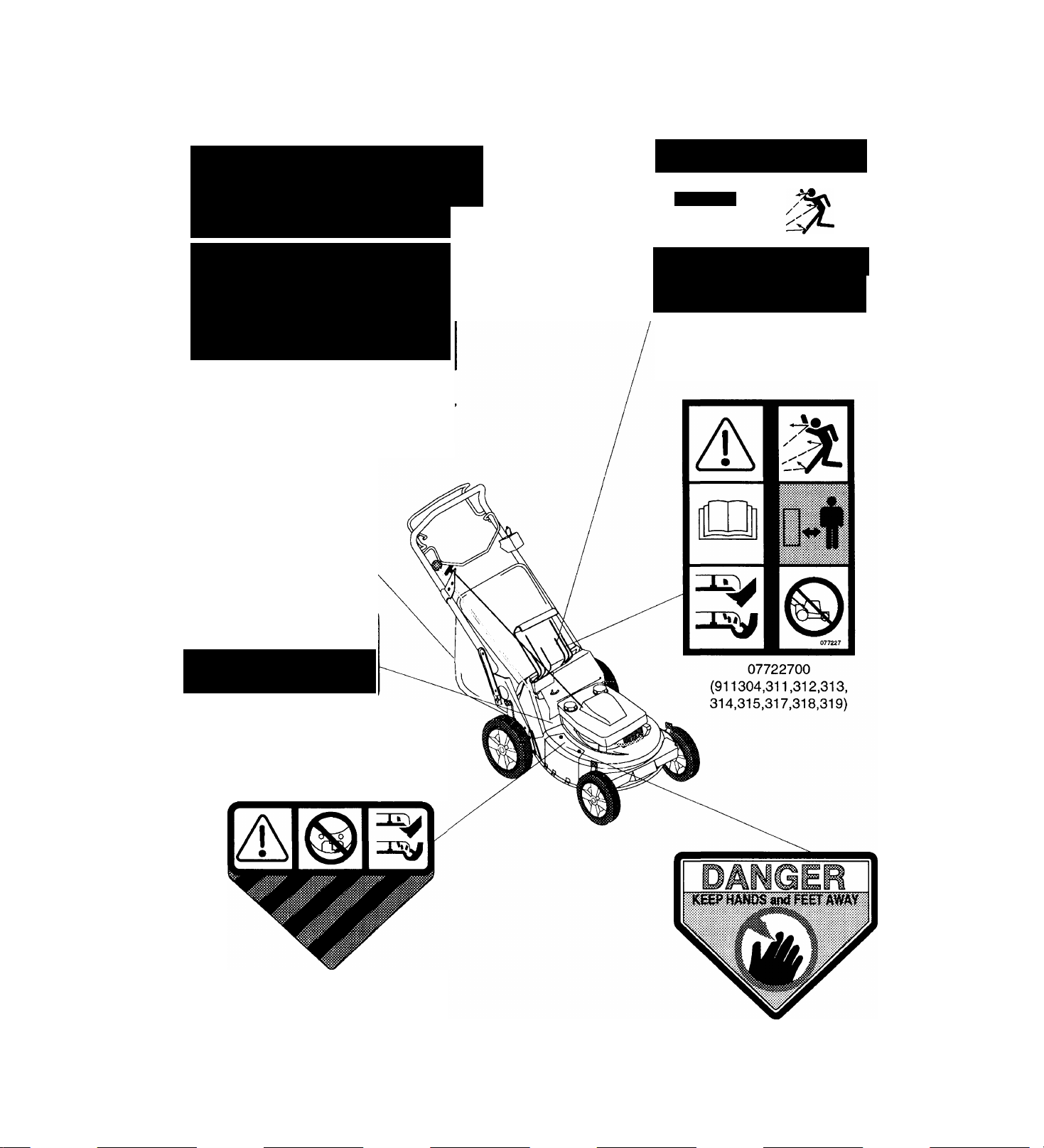
Safety Decals
AIIA Mil PH
; MM MMt it
• ENGINE MUST BE STOPPED
BEFORE CLEARING DISCHARGE.
• BLADE MUST BE STOPPED
WHEN DOOR IS OPENED.
07759200
(911065,067,068,069,070,071,072,
073,469,470,471,472,473)
▲WARNING
Do not operate mower unless
guards are in operating
position or bagger is attached.
07893700
(911065,067,068,069,070,071,072,
073,469,470,471,472,473)
(07722800)
(911304,311,312,313,
314,315,317,318,319)
Figure 1: Safety Decals
5
07874200
(911065,067,068,069,070,071,
072,073,469,470,471,472,473)
Page 8
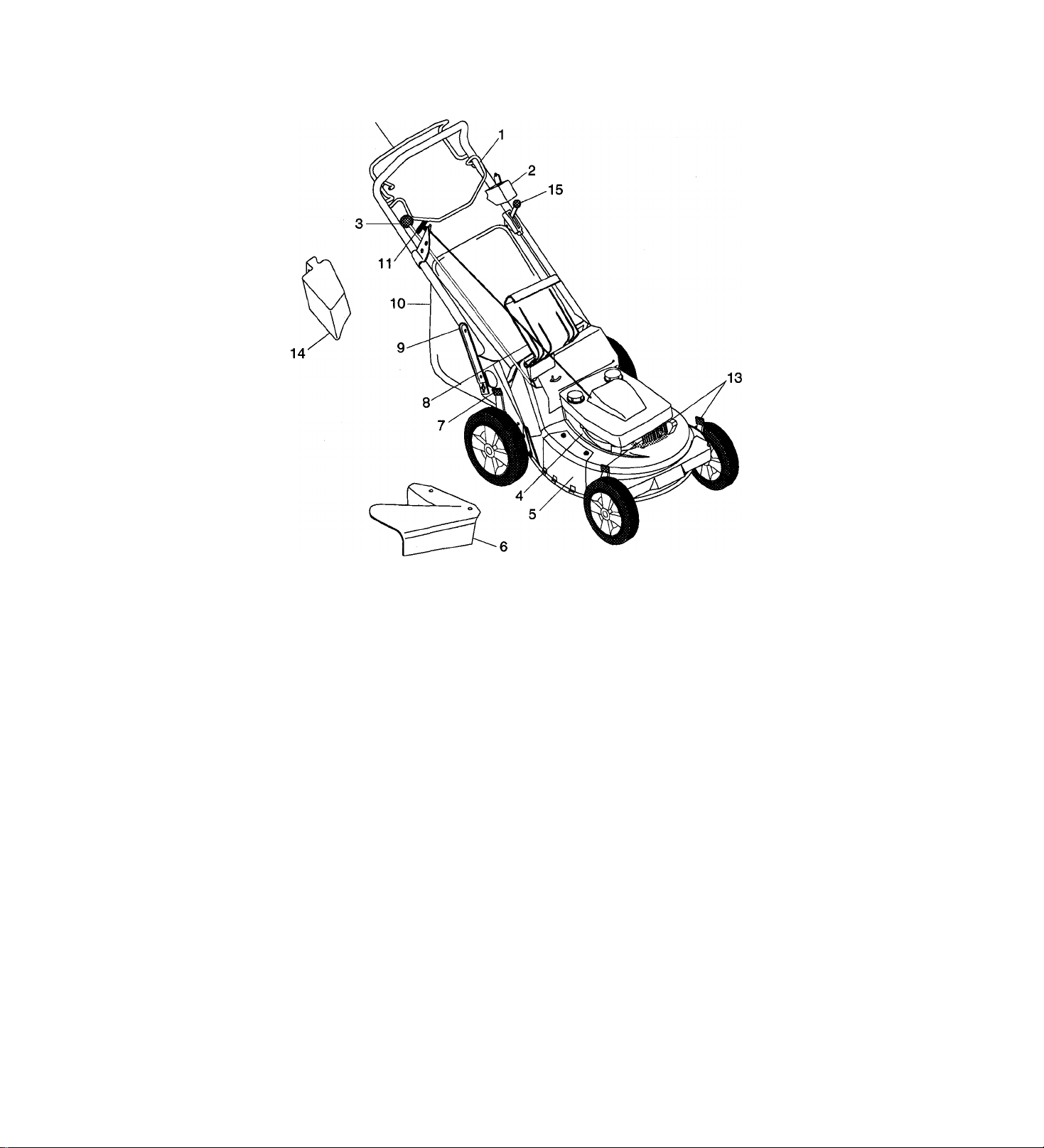
Controls and Features
12
2.
3.
4.
5.
6.
7.
8.
9.
10.
11.
12.
13.
14.
15.
1.
Engine Control
Electric Start Control (Electric Start Models)
Speed Selector (Self Propelled Models)
Primer
Side Discharge Opening Cover
Side Discharge Deflector
Cutting Height Levers (Wheel Adjustors)
Rear Door
Adjustable and Folding Handlebars
Grass Bag
Rewind Starter
Wheel Drive Control (Self Propelled Models)
Cutting Height Levers (Wheel Adjustors - See Page 9 For Swivel Wheel Models)
Mulch Master™ Plug
Throttle Control (Professional Models)
Figure 2: Control and Feature Locations
Page 9

Operation
PRE-STARTING
• Check that engine crankcase oil is at proper level
using dipstick. Fill or change as per instructions
in Lubrication and Maintenance Section. Two
cycle engines require that oil be mixed with fuel.
NOTE: This product is equipped with an internal
combustion engine. DO NOT use on or near any
unimproved, forest or brush covered land unless the
exhaust system is equipped with a spark arrester
meeting applicable local, state or federal laws. A
spark arrester, if used, must be maintained in
effective working order by the operator. See your
Ariens Dealer or engine manufacturer’s service
center.
CAUTION: Make sure all hardware is
tight, aii safety devices in place and all
A
adjustments made correctly.
Check air cleaner for dirt. Clean as required. See
Lubrication and Maintenance Section of this
manual.
Fuel
WARNING: Gasoline is highly flammable
A
and must be handled with care. Allow
engine to cool several minutes before
removing fuel tank cap. Never fill tank
when engine is running or is hot from
operation. DO NOT allow open flame,
matches, or smoking in area. DO NOT
over fill. Allow about 1/4” of tank space
for fuel expansion. Wipe up any spills
and allow vapors to dissipate before
starting engine. Use approved (Red)
gasoline container.__________________
W) approved oil. One gallon of gasoline requires 2.5
ounces of oil.
IMPORTANT: Observe the recommended gasoline
to oil mixing ratio to prevent engine damage.
To assure thorougn mixing of gasoline and oil, fill
container partially with gasoline, add oil, shake
container vigorously, add remainder of gasoline into
container and shake vigorously
Handlebar Height
Handlebar adjusts to four positions by selecting holes
in braces. Select a safe comfortable height and place
pin through hole in brace that is closest to that height.
Refer to Adjustment Section. (On professional
models, 911065 and 911317 nuts and carriage bolts
replace pin). Adjust handlebar to a safe, comfortable
operator height according to instructions in
Adjustments Section of this manual.
Mower Configurations
WARNING: DO NOT operate mower
unless either side discharge opening
A
To configure your mower for bagging, side discharge
or mulching, proceed as follows:
Bagging: Lift rear door, place bar of grass bag frame
on lip of mounting flange and lower rear door. If
necessary, lift rear of grass bag frame to lock in
position.
cover or side discharge deflector is
instalied. Objects may be picked up and
thrown causing damage or personal
injury. Never operate engine with rear
door open unless grass bag is in place.
NOTE: To prevent foreign particles from entering
tank while filling: wipe dust, dirt and debris from
around cap before removing it.
• Check fuel supply.
For 4 cycle engine, fill fuel tank with a good grade of
fresh lead free gasoline. DO NOT use premium,
gasohol, or mix gasoline with oil. (Use of lead free
gasoline produces fewer combustion deposits.
For 2 cycle engine, the recommended gasoline to oil
ratio is 50:1. For every 50 parts of gasoline, mix one
part Boating Industry Association two cycle (BIA TC-
Be sure there are no openings between bag and
mounting surface after installing bag, if necessary
clear bag mounting surface of debris.
To,remove grass bag, lift rear door. Then with
handle, lift bag up off mounting flange and close rear
door.
CAUTION: Objects may be thrown.
Check Grass Bag frequently for wear or
A
deterioration. Replace worn or
damaged bag with Ariens original
equipment replacement part only.
Page 10
Operation (Continued)
Side Discharge: With grass bag removed, remove
two lock nuts and washers that secure side discharge
opening cover to mower. Lift cover to free tabs from
slots and remove cover from mower.
Position holes in side discharge deflector over studs
on mower with tab on rear edge of deflector placed
onto edge of discharge opening. Secure deflector
with cover hardware.
CAUTION: NEVER direct discharge of
A
Muiching: With grass bag removed and side
discharge opening cover installed, install the
Mulchmaster Plug by the handle with the beveled
face to the left. Open rear door and insert
Mulchmaster Plug. Rear door will close flush with
proper insertion.
For maximum mulching performance, install the
mulchmaster mulching kit. Installation instructions
are provided in the accessory kit.
material toward bystanders nor allow
anyone near equipment while unit is in
operation.
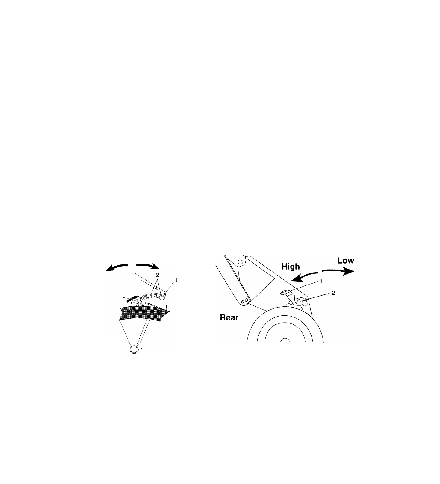
Cutting Height - Standard Models
DANGER: To avoid inadvertent biade
A
A
To change cutting height, move Cutting Height levers
one notch at a time on each wheel until desired
height of cut is obtained.
NOTE: Each Wheel on mower must be set at the
same height for a level cut.
Low Setting = 1-1/4" cut grass length.
Second Notch = 1 -3/4" cut grass length.
Third Notch = 2-1/8" cut grass length.
Fourth Notch = 2-5/8" cut grass length.
Fifth Notch = 3" cut grass length.
High Setting = 3-1/2" cut grass length.
contact, NEVER attempt to make any
cutting height adjustments while
engine is running.
CAUTION: On self-propelled models,
both rear wheels must be positioned at
same height or traction drive may not
clutch or operate properly.
r
Low
Front
r
High
1. Cutting Height Lever
2. Notch
Figure 3: Cutting Height Levers (Wheel Adjusters)
r
Page 11
Operation (Continued)
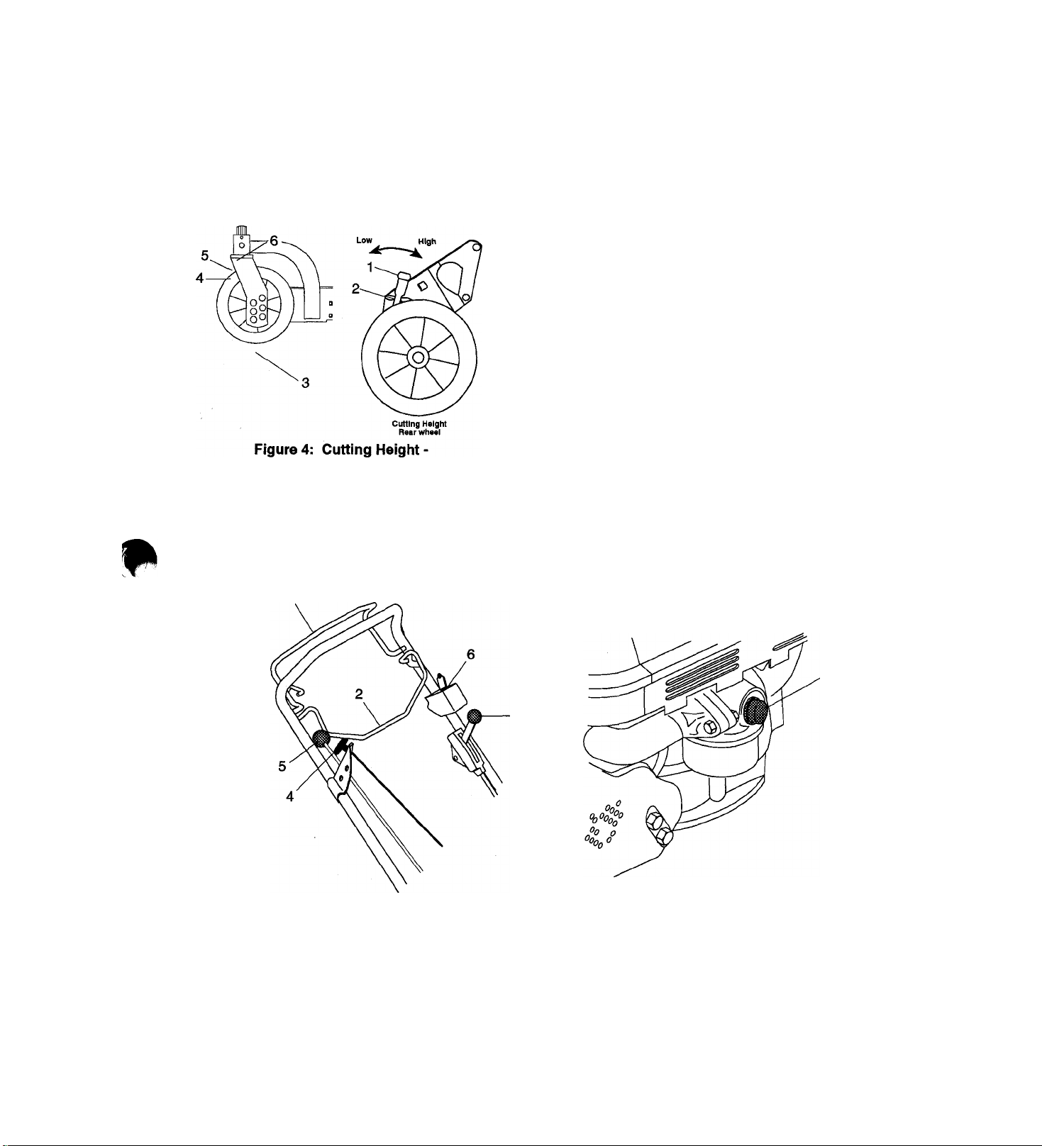
Cutting Height - Swivei Models
To change front wheel cutting height, insert clevis pin
into the holes that corresponds to the desired cutting
height. (Figure 4).
Swivel Models
STARTING
To change rear wheel cutting height, move cutting
height levers one notch at a time until the desired
cutting height is obtained. (Figure 4)
1. Cutting Height Lever
2. Notches
3. Clevis Pin & Swivel Height Adjustment Holes
4. Grease Fitting
5. Swivel Lock Hole (Clevis Pin Thru To Lock)
6. Lynch Pin Storage Hole (Clevis Pin Thru To
Swivel)
WARNING: DO NOT attempt to start
your engine at this time. Familiarize
A
yourself with controls to see what they
do, how they work and thoroughly read
and understand entire Operator's
Manual first.
1. Wheel Drive Control (Self Propelled Model)
2. Engine Control
3. Primer
4. Rewind Starter
5. Speed Selector (Self Propelled Model)
6. Key Switch (Electric Start Model)
7. Throttle Control (Professional Models Only)
Figures: Controls
Page 12

Operation (Continued)
Primer
To start a cold engine, push Primer bulb three
times.
Throttle
For engines with a choke, place throttle control in
the choke position. Once the engine has started,
place throttle in the high speed detent.
NOTE: It is not necessary to prime or choke a warm
engine.
Engine/Blade Control
The engine is equipped with a switch, that stops
the engine ignition, and a brake, that stops the
engine (blade), within 3 seconds after the
operator releases the Engine Control. The
Engine Control must be held against the
handlebar in order to start the engine as well as
during mowing operations to keep the engine
running. Releasing the control during operation
stops the engine and blade.
CAUTION: Function of Engine/Blade
A
Control should be checked regularly
per instructions in Adjustments Section
of this manual. Improper function of
control could contribute to operator or
bystander injury.
(Recoil may be used to start the engine. The key
must be in the on position.) "
Wheel Drive Control (self-propelled models)
CAUTION: Holding Wheel Drive Control
A
of self-propelled models against
handlebar, when attempting to start
mower, will propel mower forward.
On self-propelled models, with engine running,
slowly squeeze and hold Wheel Drive Control
against handlebar to propel mower forward.
Release Wheel Drive Control to stop forward
motion.
Speed Selector (self-propelled models)
Speed Selector is used to select variable forward
travel speeds of mower.
Lowest speed is when Speed Selector is pulled all
the way to rear and highest speed is provided when it
is pushed all the way forward.
With Speed Selector set at a slow travel speed and
engine running, engage Wheel Drive Control, then
increase speed with Speed Selector to a safe
comfortable walking pace. Once speed has been
selected. Speed Selector should remain in this
position, if not, adjust speed control bell crank spring
tension per instructions in Adjustments Section.
r
Rewind starter
Grasp Rewind Starter handle and pull rope out
slowly until it pulls harder (this is the compression
stroke) and let rope rewind slowly. Then pull rope
with rapid continuous full arm stroke to start
engine and allow rope to rewind slowly.
IMPORTANT: DO NOT let starter rope snap back
against bracket.
Repeat above instructions until engine starts. (Refer
to engine manufacturer’s instructions.)
NOTE: Start engine (blade) on a hard level surface
that is free of debris. To start on lawn, push down on
handlebar to allow blade to rotate above grass.
Electric Start
On electric start models, turn the key with the
Engine Control held against the handlebar.
Stopping
Release control, and allow engine to cool. On
electric start models turn key to off position after
releasing controls
CAUTION: Remove wire from spark
plug to prevent accidental starting or
A
unauthorized use of mower.
Operating Tips
The following tips will help you to mow safely,
achieve maximum performance from your mower and
maintain the appearance of your lawn.
When Bagging, be sure to release Engine/Blade
Control before attempting to remove and empty grass
bag. Empty bag before it becomes overloaded, clogs
mower and/or affects performance.
10
Page 13

Operation (Continued)
mowing. By changing direction of mowing (when
CAUTION: If clog or obstruction prevents
grass flow, release Engine/Blade Control
A
and disconnect spark plug wire before
attempting to clear away any clogs.
CAUTION: On swivel wheel models when
mowing on slopes it is recommended that
A
the lynch pin be positioned thru the swivel
lock hole. If wheels are in the swivel
position and control handles are released
the mower may "free roll" downhill. Never
mow on steep slopes.
possible) you can prevent this.
When using side discharge, turn clockwise (right turn)
when beginning to mow large open areas. This
discharges clippings away from borderline objects
(sidewalks, driveways, fences, etc.). After making a
clockwise pass, mow in a counterclockwise (left turn)
direction. This discharges clippings evenly over cut
grass. Continuous clockwise mowing will cause a build
up of clippings, preventing a uniform cut. Also, plan
cutting so that you always trim with the ieft side of
mower when using side discharge.
Restarting engine will be easier if mower is allowed to
completely discharge clippings before stopping engine.
On electric start model, if starter will not cycle because
of grass buildup under deck, rotate blade with rewind
starter to clear blockage.
Be sure your mower blade is sharp. A dull blade will tear
grass blades. This usually results in a white cast over a
freshly cut lawn. Later, tips of grass blades will turn
brown.
A new lawn has much softer blades of grass and has a
higher moisture content. It is important for this type of
lawn to be cut with sharp blades.
Cutting height will vary with different types of grass,
climate and individual preference. Generally, grass
should be cut about 1-1/2” long in spring, and not less
than 2” long in hot summer weather.
If grass is high, or if it contains a high degree of
moisture, cut it first with mower set high and then cut it
with mower set lower. This gives better distribution or
collection of clippings and provides a clean second cut.
A good fertilization program and frequent watering will
keep your lawn weed free and green all year long. Due
to variations in climate, soil and grass varieties, contact
your local garden supply dealer, park or golf course
superintendent, or county agent to obtain specific
information pertaining to your area.
NOTE: Be sure to empty grass bag and clean mower
pan after each use. A dirty unit may not bag and/or cut
grass properly.
Do not allow grass clumps or a coating of grass and
debris to collect inside of grass bag or mower pan.
Avoid operating over bare ground intermittent with grass
cuttings as this causes dirt and grass to collect and cake
under pan surface as well as in grass bag. To tip mower
for cleaning under side of pan refer to Lubrication and
Maintenance section of this manual.
Grass bag should be washed with hose and allowed to
dry. Washing grass bag prevents debris buildup, that
will clog mesh of bag, which will prevent proper air
circulation and bagging of grass.
Mulching Tips
Height of cut should not be set too low on thick, lush
lawns. Such grass, if cut too short, may die. This also
applies to springy, heavy growth lawns. If blade is set
too low, mower pan will drag on grass and restrict air
flow thus reducing discharge or collection of clippings.
Grass should be cut when it is dry; not when it is wet
from dew, rain or from watering. When wet, grass tends
to pack inside mower pan or chute and will not
discharge, mulch or bag properly, especially if height of
cut is set too low.
To insure most complete and even cut, overlap each
swath.
Following the same pattern each time you mow your
lawn can develop ridges at right angles to direction of
For best performance, it is recommended that the height
of cut for your mower be set at, or as near as possible
to, 3 inches and that not more than 1 inch of grass is
removed per cutting. This can be controlled easier by
obsen/ing the “Mulching Zone Decal” (Part No. 077123).
The decal serves as a height gage for measuring the 1
inch maximum per cutting range.
Grass should be cut when it is dry, not when it is wet
from dew, rain, or from watering. When wet, the grass
will tend to ball and pack inside the mower pan and will
not disperse evenly. If the grass does not disperse
evenly, it is probably because too much grass is being
removed per cutting, the grass is too wet, or the travel
speed is too fast.
11
Page 14

Lubrication and Maintenance
Ariens Dealers will provide any service which may be
required to keep your mower operating at peak
efficiency. Should engine repair or service be
required, it can be obtained from an Ariens Dealer or
an authorized engine manufacturer’s service center.
WARNING: Stop engine, wait for moving
parts to stop, and remove wire from
A
A
spark plug (keep wire away from plug to
prevent accidental starting) before
attempting any lubrication or
maintenance procedures.
CAUTION: DO NOT touch engine or
parts which are hot from operation.
Allow such parts to cool before
servicing
General
Mower does not require any lubrication. Wheel
assemblies are .designed for long life without
additional lubricatiori. (The professional models
911065 and 911317 has zerk fittings on drive carrier
and rear axle).
Service Positions
Pi
Figure 6: Handlebar Service Position
NOTE: On the models with Kawasaki engines,
remove the side discharge deflector, if so equipped,
prior to tipping the machine.
NOTE: A piece of plastic bag may be used to seal
fuel tank opening when tipping mower. To seal,
remove fuel tank cap, cover fuel tank opening with
plastic, replace and tighten cap securely before
tipping mower. Be sure to remove plastic before
attempting to operate mower.
A handlebar service position is provided, for tipping
the unit, for convenient cleaning and service
operations.
To place handlebar into the handlebar service
position, remove braces from pins, rotate handlebar
forward and place pins into holes of braces. See
Figures 6 and 13.
NOTE: Nuts and bolts replace pins on Professional
Models.
IMPORTANT: When tipping to service engine or unit,
use the following service positions for the brand and
type of engine on your mower:
Tecumseh Vector and Centura Engines; place
handlebar into handlebar service position and tip
machine to the rear.
Briggs & Stratton Quantum and Diamond Plus
Engines; place handlebar into handlebar service
position and tip the machine to the left, opposite the
side descharge deflector.
Kawasaki Engines; place handlebar into handlebar
service position and tip machine to the right, side
discharge deflector side.
WARNING: Gasoline is highly flammable
A
IMPORTANT: If 4 cycle engine becomes “flooded”
due to tipping, clean air cleaner. Gasoline, drawn into
cylinder may wash cylinder wall and shorten engine
life. If cylinder wall becomes washed with gasoline,
remove spark plug, put one teaspoon of oil in
cylinder, turn engine over a few times and replace
spark plug.
and must be handled with care.
Engine Oil (4 cycle engines)
Use a high quality detergent oil classified “For API
Service SF or SG” with a single viscosity SAE30.
Capacity is approximately 1-1/4 pints. Detergent oils
keep engine cleaner and retard formation of gum and
varnish deposits. DO NOT add anything to
recommended oil.
Checking
The engine crankcase oil should be checked daily or
every five (5) hours of operation.
To check oil, place mower on flat, level surface. Wipe
all debris from around oil fill cap.
12
Page 15

Lubrication and Maintenance (Continued)
To check oil, place mower on flat, level surface. Wipe
all debris from around oil fill cap.
Turn cap, remove dipstick from engine and wipe oil
off dipstick. Insert dipstick into fill hole and turn slowly
until cap bottoms firmly. Remove dipstick and
observe oil level. If low, add fresh clean oil (of same
type and viscosity as is in engine) to bring oil level to
full (F) mark. Replace dipstick being sure to tighten
cap firmly.
IMPORTANT: DO NOT over fill. Level must not
exceed full (F) mark. Oil level MUST be maintained in
safe operating range on dipstick at all times or engine
damage will result.
Changing Oil
IMPORTANT: Change engine crankcase oil after
first two (2) hours of operation, thereafter, change oil
every twenty fiye hours of operation (more often in
dusty dirty conditions).
NOTE: Run engine just prior to changing oil. Oil will
flow more freely and carry away more contaminant’s
when warm.
Place mower into the Service Position specified for
your brand and type of engine. (See Service
Positions section). Professional models 911065 and
911317 remain in the operator’s position. Attach oil
drain hose to end of engine oil drain. Place a
suitable container under oil fill, remove oil fill cap with
dipstick and allow oil to drain into container.
Place machine back onto wheels, add fresh clean oil
to proper level and be sure to replace oil fill cap with
dipstick.
4 Cycle Briggs & Stratton
Quantum & Diamond Plus Engine
1. Oil Fill Cap and Dipstick
2. Air Cleaner
3. Spark Plug and Wire
4. Fuel Cap and Tank
13
Page 16

Lubrication and Maintenance (Continued)
4 Cycle Tecumseh Engine
Centura Engine
1. Oil Fill Cap and Dipstick
2. Air Cleaner
3. Spark Plug and Wire
4. Fuel Cap and Tank
Air Cleaner
IMPORTANT: DO NOT run engine with air cleaner
removed. Operating engine with dirty air cleaner for
only a brief time can cause engine damage.
14
Page 17

Lubrication and Maintenance (Continued)
Inspect air cleaner every 10 hours of operation or
every month, whichever occurs first.
When dirty, filter elements should be removed and
cleaned per the following instructions.
NOTE: Inspect air cleaner more often if unit is used
under dirty dusty conditions.
A
CAUTION: Periodically clean muffler
and manifold areas to remove all grass,
dirt and combustible debris. If engine
muffler is equipped with spark arrester
screen assembly, remove every 50
hours for cleaning and inspection.
Replace if damaged.
To inspect and/or clean remove cover and filter
element(s) and/or cartridge from air cleaner body.
NOTE: Clean air cleaner cover and body before
installing clean or new components.
Foam Filter Element (Pre-cleaner) - Wash foam
elements in warm water with detergent. Rinse
thoroughly until all traces of detergent are eliminated,
squeeze (don’t wring) away excess water and air dry.
Soak foam element in clean fresh oil, wrap in paper
towel or rag and squeeze out excess oil.
Cartrldge/Or Paper Filter Element - Clean by
tapping gently on flat surface. Replace if it is very
dirty or becomes distorted.
Engine Cooling
The engine is air cooled. Air must circulate freely
around engine and over cooling fins on cylinder head
and block to prevent overheating.
Once a year or every one hundred (100) operating
hours (more often if conditions require) clean engine
fins and external surfaces of engine of dust, dirt, and
oil deposits which can contribute to improper cooling.
IMPORTANT: DO NOT operate engine with blower
housing removed - this will cause overheating and
engine damage.
Spark Plug
Spark plug should be cleaned or replaced (if
necessary) and gap reset to .030” every 100 hours of
operation or yearly whichever comes first.
To clean, remove debris from area around spark plug
base, remove spark plug from engine, scrape and
wash with a commercial solvent. DO NOT blast
clean.
NOTE: Sparking can occur if wire terminal does not
fit firmly on spark plug. Reform terminal if necessary.
Muffler
Worn out mufflers are more than just a noise
nuisance and should be replaced immediately.
Continued use could result in fire or explosion.
Mower Blade
CAUTION: Use sturdy gloves or
padding to protect hands when working
A
Regularly check mower blades for wear and that lock
washer is fully compressed by cap screw (requires
25-30 foot pounds of torque on cap screw.
with mower blades.
15
Page 18

Lubrication and Maintenance (Continued)
WARNING: Stop engine, wait for
A
When blade needs sharpening, block blade to
prevent rotation, remove cap screw(s), lock washer(s)
and blade from shaft.
Sharpen both ends of blade at original angle (25
degrees), removing equal amounts of material from
each end to maintain proper blade balance. New
blades are balanced to within 1.3 inch ounces at
factory, DO NOT grind around corner at tip of blade.
moving parts to stop and remove wire
from spark piug before attempting any
maintenance procedures.
If cutting edge of blade cannot be sharpened in a
straight line to within 1/8 of an inch of its end, replace
blade with Ariens replacement blade only. Blades
are available through your Ariens Dealer.
Install blade, lock washer(s) and tighten cap screw(s)
until lock washer is fully compressed (requires 25-30
foot pounds of torque on nuts).
NOTE: The 01172300 mulching blade is the only
blade to be used with the mulchmaster insert dome.
IMPORTANT: If mower is used under sandy soil
conditions, replace blades when air lifts become
eroded through at end.
Cutting Edge 4. Idler
1.
Square Corner
2.
3. Air Lift Erosion
4. Air Lift
Reverse Lift
5.
Figured: Mower Blade
16
Blade
1.
Cap Screws,Lock Washer,
2.
& Flat Washer
Drive Belt
3.
Figure 9: Mower Blade Replacement
Page 19

Lubrication and Maintenance (Continued)
IMPORTANT: Use battery supplied only. DO NOT
attempt to “jump start” mower.
To charge with battery charger, connect charger plug
to mating plug on battery (not engine) and plug
charger into 120 volt Alternating Current (A.C.) outlet.
Charge for 24 to 48 hours (battery may be charged
for up to 72 hours with no harmful effects).
An engine run time of at least 8 hours is required to
charge a fully discharged battery.
Swivel Lubrication (swivel models)
DANGER: To avoid inadvertent biade
1. Drive Belt
A
contact, NEVER attempt iubrication or
maintenance procedures whiie the
engine is running.
Figure 10: Drive Beit
Drive Belt (self propelled models)
To remove drive belt, position right hand rear wheel
Height Adjustment lever in first notch and left hand
rear wheel Height Adjustment lever in third notch.
This provides clearance between friction wheel and
drive disk.
Remove belt from idler, drive disk and engine pulley.
Pull belt through opening under mower pan and over
blade.
Check idler for free rotation of pulley and movement
of pivot.
Replace drive belt in reverse order being sure that
belt seats in pulley grooves with idler positioned on
back (flat) side of belt.
Battery (electric start model)
CAUTION: Do not put battery in fire or
mutilate; battery may burst or release
A
toxic materiais. Do not short circuit;
battery may cause burns.
NOTE: Use Ariens multi-purpose grease (part
number 000150) or a good grade of general purpose
grease. Grease swivels every 10 hours of use.
NOTE: Lynch pin must be in the swivel lock hole
while lubricating.
Swivel Lock Hole
A 12 volt, 2.5 ampere hour sealed lead acid battery is
supplied with unit. Engine alternator will normally
keep battery fully charged with a 3 to 5 minute
start/run cycle.
17
Page 20

Lubrication and Maintenance (Continued)
Chart 1 shows the recommended service schedule that should be performed on a regular basis. More frequent
service may be required due to working condition, (i.e. Heavy Loads, high ambient temperatures, dusty
conditions or when airborne debris are present.) See the engine manual for maintenance instructions. Use chart
2 to record the actual hours on the hourmeter and the date at which each service item is performed.
MAINTENANCE SCHEDULE
SERVICE PREFORMED
Check Engine Oil
Check Belt Drive
Check Air Cleaner
General Lubrication
Check Drive Control
Check Mower Blade
Check Fasteners
Check Engine/Blade Controls
Check Bag Wear
DAILY
•
•
•
•
•
TIME INTERVALS BETWEEN SERVICE
10 HRS.
•
•
•
•
Chart 1
Always use genuine Ariens service parts and accessories to ensure your machines peak
performance.
18
Page 21

MAINTENANCE RECORD
■o
o
c
o
o
o
o
c
(0
c
0)
(0
■o
c
(0
£
o
SERVICE TO BE PERFORMED
General Lubrication
Check the Fasteners
Check Drive Control
Check Bag Wear
TIME INTERVALS BETWEEN SERVICE
LU
LLI LJU
LU
LU
LU
LU LU
LU
LU
LU
LU
LU
CM
■c
o>
<0
U
(0
o
n
3
Always use genuine Ariens service parts and accessories to ensure your machines peak performance.
Page 22

MAINTENANCE RECORD
■o
0)
3
c
o
o
o
o
c
(0
c
0)
+-*
c
■ <5
■o
c
(0
SERVICE TO BE PERFORMED
General Lubrication
Check the Fasteners
Check Drive Control
Check Bag Wear
TIME INTERVALS BETWEEN SERVICE
■o
o
c
o
o
CM
■c
es
sz
O
o
CM
(0
o
3
Always use genuine Ariens service parts and accessories to ensure your machines peak performance.
Page 23

Adjustments
• For storage, remove braces from pins, rotate
WARNING. Stop engine, wait for moving
parts to stop and remove wire form
A
spark plug (keep wire away from plug to
prevent accidental starting) before
attempting any adjustment procedures.
handlebar forward and place pins into holes
further up on braces.
NOTE: Nuts and bolts replace pins on Professional
models.
CAUTION: DO NOT change engine
governor setting or over speed engine.
A
"Operate engine at the governed no
load speed recommended by the Ariens
Company only." DO NOT exceed this
speed as personal injury may result.
Handlebar
• Holes in handlebar braces provide four height
positions, a service and (except on professional
models 911065 and 911317) a storage position.
• To adjust to a safe comfortable operating height,
use one of four hole positions; 1,2,3, or 4 in order
of increasing height, in brace on both sides of
mower and place pin through hole in brace. (On
professional models 911065 and 911317) use
hole positions 1 & 3,1 & 4, 2 & 3 or 2 & 4.)
Refer to illustration.
• To place handlebar into the handlebar service
position, remove braces from pins, rotate
handlebar forward and place pins into holes of
braces. See Figures 6 and 12.
Engine/Blade Control
• Engine Control must stop engine ignition, at a
point 3/4”-1 1/4” from handlebar as control is
released. To check, start engine and slowly
release Control until engine stops firing.
• Measure distance between handlebar and control
at the point that engine stopped firing.
• Turn cable nuts at handlebar mount clockwise if
measurement is more than 11/4" or
counterclockwise if measurement is less than ^
3/4". Turn nuts against mount to lock in position.
1.
Hole No. 1 5. Pin
Hole No. 2
2.
3. Hole No. 3 7.
4. Hole No. 4 8.
Figure 12: Handlebar Height
6. Brace
Professional Brace
Storage Position
21
1.
Engine Control
2. Handlebar
Cable Nuts
3.
4.
Mount
Figure 13: Engine Control
Page 24

Adjustments (Continued)
Drive Wheel (self propelled model)
• When the Wheel Drive Control is squeezed
toward the handlebar the extension spring,
located at the bottom end of the traction cable,
must start to extend when the control is between
1" and 1 -1/2" away from the handlebar. To
check, squeeze the Wheel Drive Control toward
the handlebar until the spring starts to open.
• Measure the distance between the Wheel Drive
Control and handlebar at the handlebar
indentation.
• To obtain the proper adjustment turn the cable
nuts at either the handlebar end or the bottom
end of the traction cable. Tighten the nuts
against the bracket to lock in position.
Speed Control Bell Crank
• To adjust, remove cover, fully compress the
helical spring lockwashers with lock nut and then
back lock nut off one half turn. Align notch in
L.H. side of cover with bolt and secure with knob.
1. Lock Nut
2. Helical Spring Lockwashers
3. Speed Control Bell Crank
4. Speed Control Rod
1. Traction Cable
2. Handlebar Indentation
3. Cable Nuts
4. Wheel Drive Control
Figure 14: Wheel Drive Control
Figure 15: Speed Control Bell Crank
22
Page 25

A
storage
WARNING: Never store mower in an
enclosed area where fuel fumes may
reach flame, sparks, pilot lights, or an
ignited object. Drain fuel outdoors away
from any ignition source. Use only
approved (Red) fuel container.
Remove Grass Bag and clean out all debris prior to
storage. Grass Bag may be stored in position on
mower. Keep Grass Bag dry during storage.
On electric start models, fully charge battery and
store in a cool dry location. (Refer to Battery in
Lubrication and Maintenance Section.)
Your authorized Ariens Dealer is trained and
equipped to service your mower. A periodic
checkup by your dealer will help reduce your
maintenance costs.
Inspect mower for visible signs of wear, breakage or
damage. Order any parts required and make
necessary repairs to avoid delays when beginning
use again.
Service Manual
Service manuals are available for owners who wish
to perform some of their own maintenance and
service operations. Should a complete service
manual be desired, order by referring to the model
and serial number of your machine.
When ordering parts always include the model and
serial number of your unit to assure prompt service.
A parts manual is included in your literature package
to make ordering of service parts easier.
When storing mower for an extended period, refer to
engine instruction for proper engine storage
procedures.
Clean unit thoroughly. Touch up all areas to prevent
rust. Matching touch up paint is available from your
Ariens Dealer. Store mower in a cool, dry protected
location.
Mail Request to: Ariens Service
655 West Ryan Street
P.O. Box 157
Brillion,WI 54110-0157
Walk Behind Mower Model Number.
Walk Behind Mower Serial Number.
23
Page 26

Trouble Shooting
1. Engine won’t start
Low or empty gas tank.
Spark plug wire attached.
Engine/brake control cable deattached or broken.
Engine/brake control cable adjusted properly.
Engine/brake control bail engaged.
Discharged battery.
2. Self-propelled drive does not engage
Drive belt not in position.
Drive belt in good condition.
Rear wheels in the same cutting height.
Friction Wheel engagement adjusted properly.
Friction wheel in good condition.
Idler and idler spring installed properly.
Traction drive cable deattached or broken.
Traction drive bail engaged.
Bearings in good condition.
Debris in gear set.
24
Page 27

Specifications
Model No.
Description Name
Length
Height
Width
Weight Actual
911065
LM230sp
60.5 153.7 CM
37.75 96 CM
23” 58.4 CM
113 Lbs
Engine - Manufacturer Kawasaki
- Cycles
Four
- HP (3600 rpm) 5.0 HP
Fuel Tank Cap.
1.4 Qt.
Fuel Unleaded
Primer Bulb N/A
Throttle/Choke Control
Standard
Starting Recoil
Cylinder Bore
Pressurized Oil System
Governed RPM
Crank Case Cap.
Air Cleaner
Engine Oil Type Spark Plug
Differential
Variable Speeds - MPH
Cast Iron Sleeve
Standard w/Oil Filter
2850+ - 150
19 Oz.
Dual Element
SAE. 30
.30
Standard
0-4 MPH
0-6.4 KMPH
Mower Deck Gauge
14 Gauge Stamped
Steel Steel
Baked Powder Paint
Cutting Width
Cutting Height
Standard
21” 53.3 CM
6 Positions
1.00” - 3.25” 1.25” - 3.5”
2.5 - 8.3 Cm
911067
MM223
60.5 153.7 CM
37.75” 96 CM
23” 58.4 CM
72 Lbs.
Tecumseh
Four
5.0 HP
1.5 Qt.
Unleaded
Standard
N/A
Recoil
Aluminum
Standard
2850-1--150
27 Oz.
911068
MM224SP
60.5” 153.7 CM
37.75” 96 CM
23” 58.4 CM
92.5 Lbs,
Tecumseh
Four
5.5 HP
1.5 Qt.
Unleaded
Standard
N/A
Recoil
Aluminum
Standard
2850-I--150
27 Oz.
Paper Element Paper Element
SAE. 30
.30
N/A
N/A
SAE. 30
.30
Standard
0-3.5 MPH
0-5.6 KMPH
16 Gauge Stamped
16 Gauge Stamp
Steel
Standard
21” 53.3 CM
Standard
21” 53.3 CM
6 Positions 6 Positions
1.25”-3.5”
‘3.2-8.9 CM
‘3.2-8.9 CM
Folding Handlebar Standard
One Piece
Adjustable Handle Bar
Front Wheel Dia.
Rear Wheel Dia.
Side Discharge
Bagger
4 Position
7.0” 17.8 CM
10.0” 25.4 CM
Standard
Standard
Accessory
Dethatcher
Mulchmaster Plug
Leaf Shredder
Side Discharge Chute
Rear Bagger
Swivel Wheel Kit
Rear Discharge Chute
Rear Roller Kit
Mulching Accessory
= Part of Base Model
711024 N/A
*
711028
•k
■ k
711033
711032
711034 711034
711035
25
Standard
One Piece
4 Position
7.5” 19.1 CM
10.5” 26.7 CM
N/A (Rear Opt)
Optional
•k
711028
N/A
711030
711033
711032
711035
Standard
One Piece
4 Position
7.5” 19.1 CM
10.5” 26.7 CM
N/A (Rear Opt)
Optional
711024
k
711028
N/A
711030
711033
711032
711034
711035
Page 28

Specifications
Model No.
Description Name
Length
Height
Width
Weight Actual
Engine - Manufacturer
- Cycles
- HP (3600 rpm)
Fuel Tank Cap.
Fuel
Primer Bulb
Throttle/Choke Control
Starting
Cylinder Bore
Pressurized Oil System
Governed RPM
Crank Case Cap.
Air Cleaner
Engine Oil Type
Spark Plug
Differential
Variable Speeds - MPH
Mower Deck Gauge
Baked Powder Paint
Cutting Width
Cutting Height
911069/911469
LM225sp/LM232sp
60.5 153.7 CM
37.75 96 CM
23” 58.4 CM
99.5 Lbs
Briggs & Stratton
Four
5.5 HP
1.6 Qt.
Unleaded
Standard
N/A
Recoil
Cast Iron Sleeve
Standard
2900 +-100
20 Oz.
Dual Clean
SAE. 30
.30
Standard
0-4 MPH
0-6.4 KMPH
14 Gauge Stamped
Steel
Standard
21” 53.3 CM
6 Positions
1.25”- 3.5”
‘3.2-8.9 Cm
911070/911470 911071/911471
LM226sp/LM233sp LM227sp/LM234sp
60.5 153.7 CM
37.75” 96 CM
23” 58.4 CM
102.5 Lbs.
Briggs & Stratton
Four
5.5 HP
1.6 Qt.
60.5” 153.7 CM
37.75” 96 CM
23” 58.4 CM
108.5 Lbs.
Tecumseh
Four
6.0 HP
1.5 Qt.
Unleaded Unleaded
Standard
N/A
Recoil
Cast Iron Sleeve
Standard
2900+ -100
20 Oz.
Dual Clean
SAE. 30
.30
Standard
0-4 MPH
0-6.4 KMPH
14 Gauge Stamped
Steel
Standard
21” 53.3 CM
6 Positions
1.25” - 3.5”
‘3.2-8.9 CM
Standard
N/A
Electric/Recoil
Aluminum
Standard
2850 +-150
27 Oz.
Paper Element
SAE. 30
.30
Standard
0-4 MPH
0-6.4 KMPH
14 Gauge Stamped
Steel
Standard
21” 53.3 CM
6 Positions
1.25” - 3.5”
‘3.2-8.9 CM
Folding Handlebar
Adjustable Handle Bar
Front Wheel Dia.
Rear Wheel Dia.
Side Discharge
Bagger
Accessory
Dethatcher
Mulchmaster Plug
Leaf Shredder
Side Discharge Chute
Rear Bagger
Swivel Wheel Kit
Rear Discharge Chute
Rear Roller Kit
Mulching Accessory
= Part of Base Model
Standard
One Piece
4 Position
7.5” 19.1 CM
10.5” 26.7 CM
Standard
Standard
711024
•k
711028
*
•k
711033
711032
711034
711035
26
Standard
One Piece
4 Position
7.5” 19.1 CM
10.5” 26.7 CM
Standard
Standard
N/A
к
711028
к
к
*
711032
711034
711035
Standard
One Piece
4 Position
7.5” 19.1 CM
10.5” 26.7 CM
Standard
Standard
N/A
к
711028
к
к
к
711032
711034
711035
Page 29

Specifications
Model No.
Description Name
Length
Height
Width
Weight Actual
Engine - Manufacturer
- Cycles Four
- HP (3600 rpm) 6.0 HP
Fuel Tank Cap. 1.5 Qt.
Fuel Unleaded
911072/911472
LM228sp/LM235sp
60.5 153.7 CM
37.75 96 CM
23” 58.4 CM
99.5 Lbs
Tecumseh
911073/911473
LM229sp/LM236sp
60.5 153.7 CM
37.75 96 CM
23” 58.4 CM
102.5 Lbs.
Tecumseh
Four
6.0 HP
1.5 Qt.
Unleaded
Primer Bulb Standard Standard
Throttle/Choke Control N/A
Starting
Recoil
Cylinder Bore Aluminum
N/A
Recoil
Aluminum
Pressurized Oil System Standard Standard
Governed RPM
Crank Case Cap.
2850+ -150 2850-1--150
27 Oz.
27 Oz.
Air Cleaner Paper Element Paper Element
Engine Oil Type .
Spark Plug
SAE. 30
.30
SAE. 30
.30
Differential Standard Standard
Variable Speeds - MPH 0-4 MPH
i
Mower Deck Gauge
0-6.4 KMPH
14 Gauge Stamped
Steel
0-4 MPH
0-6.4 KMPH
14 Gauge Stamped
Steel
Baked Powder Paint Standard Standard
Cutting Width 21” 53.3 CM 21” 53.3 CM
Cutting Height 6 Positions
1.25”- 3.5”
3.2-8.9 CM
6 Positions
1.25” - 3.5”
3.2-8.9 CM
Folding Handlebar Standard Standard
One Piece One Piece
Adjustable Handle Bar 4 Position 4 Position
Front Wheel Dia. 7.5” 19.1 CM
7.5” 19.1 CM
Rear Wheel Dia. 10.5” 26.7 CM 10.5” 26.7 CM
Side Discharge
Standard Standard
Bagger \ Standard Standard
1
Accessory
Dethatcher
Mulchmaster Plug
Leaf Shredder
Side Discharge Chute
Rear Bagger
Swivel Wheel Kit
Rear Discharge Chute
1 Rear Roller Kit
711024
* it
711028 711028
* *
it
711033
N/A
*
*
711032 711032
711034 711034
Mulching Accessory 711035 711035
Part of Base Model
27
Page 30

Specifications
Model No.
Description Name
Length
Height
Width
Weight Actuai
Engine - Manufacturer
- Cycles
- HP (3600 rpm)
Fuel Tank Cap.
Fuel
Primer Bulb
Throttle/Choke Control
Starting
Cylinder Bore
Pressurized Oil System
Governed RPM
Crank Case Cap.
Air Cleaner
Engine Oil Type
Spark Plug
Differential
Variable Speeds - MPH
Mower Deck Gauge
Baked Powder Paint
Cutting Width
Cutting Height
911304 911311
LM21
60.5 153.7 CM
LM21S LM21sm
60.5 153.7 CM
37.75 96 CM 37.75” 96 CM
23” 58.4 CM
81.5 Lbs
Briggs & Stratton
Four
5.0 HP
1.5 Qt.
Unleaded
N/A
Standard
Recoil
Aluminum
Standard
2900+ -100
20 Oz.
Paper Element
SAE. 30
.30
N/A
N/A
23” 58.4 CM 23” 58.4 CM
96.5 Lbs. 97.2 Lbs.
Briggs & Stratton
Four
5.0 HP
1.5 Qt.
Unleaded
N/A
Standard N/A
Recoil
Aluminum
Standard
2900-I--100
20 Oz.
Paper Element
SAE. 30
.30
Standard
0-4 MPH
0-6.4 KMPH
14 Gauge Stamped
Steel
Standard
21” 53.3 CM
6 Positions
1.25”- 3.5”
3.2-8.9 CM
14 Gauge Stamped
Steel
Standard
21” 53.3 CM
6 Positions
1.25”-3.5”
3.2-8.9 CM
911312
60.5” 153.7 CM
37.75” 96 CM
Tecumseh
Four
6.0 HP
1.5 Qt.
Unleaded
Standard
Recoil
Aluminum
Standard
2850+ -150
27 Oz.
Paper Element
SAE. 30
.30
Standard
0-4 MPH
0-6.4 KMPH
16 Gauge Stamped
Steel
Standard
21” 53.3 CM
6 Positions
1.25”-3.5”
3.2-8.3 CM
Folding Handlebar
Adjustable Handle Bar
Front Wheel Dia.
Rear Wheel Dia.
Side Discharge
Bagger
Accessory
Dethatcher
Muichmaster Plug
Leaf Shredder
Side Discharge Chute
Rear Bagger
Swivel Wheel Kit
Rear Discharge Chute
Rear Roller Kit
Mulching Accessory
= Part of Base Model
Standard
One Piece
4 Position
7.5” 19.1 CM
10.5” 26.7 CM
Standard
Standard
N/A
711027
711028
*
*
711033
711032
711034
711035
28
Standard
One Piece
4 Position
7.5” 19.1 CM
10.5” 26.7 CM
Standard
Standard
711024
711027
711028
*
ic
711033
711032
711034
711035
Standard
One Piece
4 Position
7.5” 19.1 CM
10.5” 26.7 CM
N/A (Rear Opt)
Optional
711024
711027
711028
N/A
711030
711033
711032
711034
■k
Page 31

Specifications
Model No.
Description Name
Length
Height
Width
Weight Actual
Engine - Manufacturer
- Cycies Four
- HP (3600 rpm)
Fuel Tank Cap.
Fuel
Primer Bulb
Throttle/Choke Control
Starting
Cylinder Bore
Pressurized Oil System
Governed RPM
Crank Case Cap.
Air Cleaner
Engine Oil Type
Spark Plug
Differential
Variable Speeds - MPH
Mower Deck Gauge
Baked Powder Paint
Cutting Width
Cutting Height
911313
LM21S
60.5 153.7 CM
37.75 96 CM
23" 58.4 CM
99.5 Lbs
Tecumseh
6.0 HP
1.5 Qt.
Unleaded
Standard
N/A
Recoil
Aluminum
Standard
2850 +-150
27 Oz.
Paper Element
SAE. 30
.30
Standard
0-4 MPH
0-6.4 KM PH
14 Gauge Stamped
Steel
Standard
21” 53.3 CM
6 Positions
1.25”- 3.5”
3.2-8.9 CM
911314
LM21SW
60.5 153.7 CM
37.75” 96 CM
23” 58.4 CM
102.5 Lbs.
Tecumseh
Four
6.0 HP
1.5 Qt.
Unleaded
Standard
N/A
Recoil
Aluminum
Standard
2850+ - 150
27 Oz.
Paper Element
SAE. 30
.30
Standard
0-4 MPH
0-6.4 KMPH
14 Gauge Stamped
Steel
Standard
21” 53.3 CM
6 Positions
1.25” - 3.5”
3.2-8.9 CM
911315
LM21se
60.5” 153.7 CM
37.75” 96 CM
23” 58.4 CM
105.5 Lbs.
Tecumseh
Four
6.0 HP
1.5 Qt.
Unleaded
Standard
N/A
Electric/Recoil
Aluminum
Standard
2850+ -150
27 Oz.
Paper Element
SAE. 30
.30
Standard
0-4 MPH
0-6.4 KMPH
14 Gauge Stamps
Steel
Standard
21” 53.3 CM
6 Positions
1.25” - 3.5”
3.2-8.9 CM
Folding Handlebar
Adjustable Handle Bar
Front Wheel Dia.
Rear Wheel Dia.
Side Discharge
Bagger
Accessory
Dethatcher
Mulchmaster Plug
Leaf Shredder
Side Discharge Chute
Rear Bagger
Swivel Wheel Kit
Rear Discharge Chute
Rear Roller Kit
Mulching Accessory
= Part of Base Model
Standard
One Piece
4 Position
7.5” 19.1 CM
10.5” 26.7 CM
Standard
Standard
711024
711027
711028 711028
*
*
711033
711032
711034
711035
29
Standard
One Piece
4 Position
7.5” 19.1 CM
10.5” 26.7 CM
Standard
Standard
N/A
711027
*
it
it
711032
711034
711035
Standard
One Piece
4 Position
7.5” 19.1 CM
10.5” 26.7 CM
Standard
Standard
711024
711027
711028
it
it
711033
711032
711034
711035
Page 32

Specifications
Model No.
Description Name
Length
Height
Width
Weight Actual
911316 911317
LM21SCSW LM21SCSW
60.5 153.7 CM
37.75” 96 CM
23” 58.4 CM 23” 58.4 CM
88 Lbs
Engine - Manufacturer N/A
- Cycles
- HP (3600 rpm)
Fuel Tank Cap.
Fuel
Primer Bulb
Throttle/Choke Control
Starting
Cylinder Bore
N/A
N/A
N/A
N/A
N/A
N/A
N/A
N/A
Pressurized Oil System N/A
Governed RPM
Crank Case Cap.
Air Cieaner
Engine Oil Type
Spark Plug
Differential
Variable Speeds - MPH
Mower Deck Gauge
Baked Powder Paint
Cutting Width
Cutting Height
N/A
N/A
N/A
N/A
N/A
Standard Standard
0-4 MPH
14 Gauge Stamped
Standard Standard
21” 53.3 CM
6 Positions
60.5 153.7 CM 60.5 153.7CM
37.75” 96 CM 37.75” 96CM
113 Lbs
Kawasaki
Four
5.0 HP
1.4 Qt.
Unleaded
N/A
Standard
Recoil
Cast Iron Sleeve
Standard w/Oil Filter
2850+ - 150
19 0z.
Dual Element
SAE. 30
.30 .30
0-4 MPH 0-3.5 MPH
0-6.4 KMPH
0-6.4 KMPH
14 Gauge Stamped
Steel
Steel
21” 53.3 CM
6 Positions
1.25” - 3.5”
1.25”- 3.5”
3.2-8.9 CM 3.2-8.9 CM
911318 911319
LM21S
LM21SW
60.50 153.7CM
37.75” 96CM
23” 58.4 CM
23” 58.4CM
99 Lbs. 99.5 Lbs.
Tecumseh
Briggs & Stratton
Two Four
5.0 HP 5.0 HP
1.5 Qt.
Unleaded/Oil (50:1)
Standard
N/A
Recoil
Aluminum
Standard
3200+ - 150
N/A
Paper Element
N/A
1.5 Qt.
Unieaded
N/A
Standard
Recoil
Aluminum
Standard
2900 100
20 Oz.
Paper Element
SAE.30
.30
Standard
Standard
0-4 MPH
0-5.6 KMPH
14 Gauge Stamped
Steel
Standard
21” 53.3 CM
6 Positions
1.25” - 3.5”
3.2-8.9 CM
0-6.4 KMPH
14 Gauge Stamped
Steel
Standard
21” 53.3 CM
6 Positions
1.25” - 3.5”
3.2-8.9 CM
Folding Handlebar
Adjustable Handle Bar
Front Wheel Dia.
Rear Wheel Dia.
Side Discharge
Bagger
Accessory
Dethatcher
Mulchmaster Plug
Leaf Shredder
Side Discharge Chute
Rear Bagger
Swivel Wheel Kit
Rear Discharge Chute
Rear Roller Kit
Mulching Accessory
= Part of Base Model
Standard
One Piece
Standard
One Piece
4 Position 4 Position
7.5” 19.1 CM
10.5” 26.7 CM
7.5” 19.1 CM
10.5” 26.7 CM
Standard Standard
Standard
N/A
Standard
N/A
711027 711027
711028
•k
■k
711033
711032
711034
711028
*
•k
711033
711032
711034
711035 711035
30
Standard
One Piece
4 Position
7.5” 19.1 CM
10.5” 26.7 CM
Standard
Standard
711024
*
711028
*
•k
711033
Standard
One Piece
4 Position
7.5” 19.1 CM
10.5” 26.7 CM
Standard
Standard
N/A
711027
711028
■k
*
711033
711032 711032
711034
711035
711034
711035
Page 33

Dealer Preparation
Consumer Note: Your Ariens Dealer is expected to
complete these preparation steps and review
important information, including this manual, with you
before or upon delivery of unit.
The preparation information is included here so that
you and your dealer may review it together.
NOTE: All references to “Left", “Right”, “Front” and
“Rear” are given from operator’s position.
WARNING: Failure to follow all
instructions could result in personal
A
Instructions contained in this manual apply to several
models of mower. Use the instructions that apply to
your unit.
injury and/or damage to mower. Remove
wire from spark plug before attempting
any adjustment or assembly procedure.
Tools Required:
None
Package Contents - All Models (except
where noted).
Side Discharge Chute (not included
in 911067 and 911068)
IMPORTANT: Engines are shipped without oil in
engine crankcase. Refer to Lubrication and
Maintenance Section for filling instructions.
Step 1
Remove the mower and other components from
shipping container.
31
Page 34

Dealer Preparation
step 2
Unfold the handlebar. Select a safe comfortable
handlebar operating height, place hole in braces onto
pins on both sides of mower. (Refer to Adjustments
Section.)
On Professional models, nuts and bolts are used to
secure handlebar.
1. Speed Selector Rod
2. Speed Control Bell Crank
3. Washer
4. Hair Pin
5. Swivel
1. Handlebar Height Adjustment Holes
Figure 16: Handlebar Set-up
Step 3 (Self Propelled Models)
On self propelled models, Speed Selector rod is
shipped on handlebar with hardware in position.
Remove hair pin and washer, insert bent end of rod
through hole in swivel of speed control bell crank,
place washer onto rod and retain with hair pin.
Figure 17: Speed Selector
Step 4
Assemble grass bag onto bag frame by sliding bag
over frame (longest side of bag is top and goes over
long side of frame).
32
3. Bag Molding
Figure 18: Grass Bagger
Page 35

Dealer Preparation (Continued)
Secure bag to each side of bag frame by separating
molding on bag enough to slide frame into molding.
Be sure molding is completely seated on all four
sides of bag frame.
To install grass bag or side discharge deflector on
mower refer to Pre-Starting in Operation Section of
this manual.
WARNING: DO NOT operate mower
unless either side discharge opening
A
cover or side discharge defiector is
instaiied. Objects may be picked up and
thrown causing damage or personai
injury. Never operate engine with rear
door open uniess grass bag is in piace.
Step 5 (electric start models)
On electric start models, battery was charged before
unit was shipped but may start mower only a few
times because of long term self discharge. Fully
charge battery before delivery of mower to customer.
(Refer to instructions in Lubrication and Maintenance
ection.)
Step 6
Engine/Blade Control feature on this mower must
cause engine and blade to stop within 3 (three)
seconds whenever operator releases control on
handlebar. Control was adjusted at factory but must
be checked according to instructions in Adjustments
Section of this manual.
Step 8
Complete Walk Behind Lawn Mower Warranty
Registration Form and mail original copy to Ariens
Company.
Warranty is registered under model and serial
number found on decal on mower pan.
Step 9
Using the Owner’s Manual, instruct customer on
controls and operation of unit. Emphasize safety and
discuss the Safety Precautions.
Explain recommended lubrication and maintenance
of the unit.
IMPORTANT: Remind customer to change oil in 4
cycle engine crankcase after first two (2) hours of
operation.
Advise customer on adjustments, demonstrate how to
install grass bag, deflector and discharge opening
cover.
Explain Ariens Company, Limited Warranty Policy,
and fill out Original Purchaser Registration Card,
Parts and Repair Manual Order Form and return to
Ariens Company. Place Model and Serial Number on
page (1) of this manual.
Give customer his Owner’s Manual and engine
manufacturer’s instructions. Advise him to thoroughly
read and understand them.
Step 7
Oil air cleaner precleaner per instructions in
Lubrication and Maintenance section of this manual
before delivery to customer.
33
Page 36

Accessories
Enhance your Walk Behind Lawn Mower with these Ariens Accessories.
71102400 Dethatcher
71102700
71102800
71102900
71103000 Grass Bag
71103200
71103300
71103400 Rear Roller
71103500
Be sure to always use genuine Ariens parts to keep your
walk behind lawn mower running like new.
Mulchmaster Plug
Leaf Shredder
Side Discharge Deflector
Rear Discharge Chute
Swivel Wheel
Mulching Accessory
34
Page 37

AraENS
PRODUCTS
GUARANTEE
LIMITED
WARRANTY
PROTECTION PLAN
e The Company will provide for the replacement of any
part found upon examination by the Cotnpany to be
defective. Such repair or replacement will be free of
charge to the purchaser (labor and parts) for two years
(24 months) from the date of purchase. Arlens
manufadured parts (but not labor) will be free of charge
for an additional throe years (36 months) thereafter.
This warranty Is subject to the following exceptions and limitations:
PURCHASER RESPONSIBILITIES -
• Maintenance & minor adjustments per owners manual
• Notification of need for warranty service
• Transportation to/from place of warranty repair
PRODUCT REGISTRATION -
• Return of registration card required to validate
warranty
PURCHASED COMPONENTS AND NORMAL WEAR -
• TVvo year labor and parts on purchased components
i.e., (tractor drive train components manufactured by
Dana, Eaton, Foote, Sundstrand and any plastic and
electrical components, wire harnesses, bags, boots
tubes, etc.).
• Two year labor and parts on normal wear items i.e.,
(belts and rubber components, bearings, cables,
controls, clutches, tines, etc.).
BATTERY WARRANTY PRORATED -
• One to six months • tree replacement
• Seven to twelve months - 50 % credit
• Thirteen to twenty-four months - 25% credit
WARRANTY - COMMERCIAL PRODUCTS -
• One year parts and labor
• Product labeled commercial/professional
• Household use - 5 year limited warranty applies
Aliens Company hereby wanants to the ori^nal consumer purchaser that
products manufactured by Aliens Company win be free from defects in material
aid workmanship FOR A PERIOD OF FIVE (5) YEARS FROM T>E DATE OF
PURCHASE, EXCEPT AS NOTED BELOW.
SERVICE -
• For warranty service, contact any Ariens Distributor or
Dealer. For the name and location of the Ariens
Distributor or Dealers in your area, and for further
warranty information, write or call the Ariens
Conpany.
ENGINES, ENGINE ACCESSORIES, AND
PEERLESS PRODUCTS -
• Covered only by manufacturer's warranty.
EXCLUSIONS -
• No warranty is extended to blades, mower vanes, skid
shoes, runners, scraper blades, shear bolts, light
bulbs, headlights and any equipment which has been
altered, misused, misassembled. Improperly
adjusted,neglected, or damaged by accident.
• No warranty is extended for service completed by
someone other than an authorized distributor or
dealer.
• No warranty is extended on any parts that are not
genuine Ariens service parts.
Ariens Company reserves the right to incorporate any changes in design
into its products without obligation to make such changes on products
previously manufactured.
DISCLAIMER OF FURTHER WARRANTY
There Is no other express warranty. Implied warranties, Including any
warranty of merchantability or fitness for a particular purpose, are limited
to the duration of this written warranty, and are excluded to the extent
permitted by law. Thera are no warranties which extend beyond the
description of the product contained herein. In no event shall the company
be liable for indirect, special or consequential damages (such as loss of
anticipated profits) in connection with the consumer's use of the product.
This warranty gives you specific legai rights, and you may also have other
rights which vary from state to state. Some states do not aiiow the
exiusion of incidentai or consequential damages, or limitations on how
long an implied warranty lasts, so the above limitation and exclusions may
not apply to you.
RENTAL USE - ALL PRODUCTS
• NINETY DAYS LABOR & PARTS
CONSUMER PRODUCT - PUT TO
COMMERCIAL, INDUSTRIAL, INSTITUTIONAL USE
• NINETY DAYS LABOR & PARTS
SERVICE PARTS AND ACCESSORIES -
• NINETY DAYS LABOR & PARTS
35
o4i
lens.
Page 38

Index
Accessories
Adjustments
Drive Wheel
Engine/Blade Control 21
Handlebar
Speed Control Bell Crank
Controls and Features
Lubrication and Maintenance
Battery Service
Drive Belt
Engine Maintenance
Maintenance Charts 18
Mower Blade
Service Positions
Swivel Wheel Lubrication
Models
Operation
Cutting Heights
Electric Start
Engine/Blade Control
Handlebar Height
Mower Configurations
Mulching Tips
Operating Tips 10-11
Primer 10
34
21
22 Throttle
21
22 Preparation
6 Steps to Assemble
12 Safety Alert Symbol and Notations
17
17 Safety Decals
12
15 Maintenance and Storage
12 Operation
17 Preparation
1-2
7
8-9 Specifications
10
10 Storage 23
7
7-8 Trouble Shooting 24
11
Rewind Starter
Speed Selector
Stopping
Wheel Drive Control
31
Package Contents
Safety Precautions 3-4
Training
Service Manual
Warranty 35
31
31-33
3-4
25-30
10
10
10
10
10
i
5
4
3
3
23
Page 39

911 Series
Obriens
NOTE: Refer to Owner’s Manual for detailed instructions.
□ 1. Unfold handlebar and adjust for height.
□ 2. Install speed selector rod if applicable.
□ 3. Install grass bag on bag frame and on unit.
□ 4. Charge battery is applicable.
□ 5. Fill engine crankcase with recommended oil.
□ 6. Add recommended fuel.
Walk Behind Lawn Mowers
Dealer Preparation
Checklist
□ 7. Start engine and check engine control.
□ 8. Check wheel drive control.
□ 9. Complete Warranty Registration form and mail to Ariens Company.
□ 10. Using Owner’s Manual Instruct customer on controls and operation of unit. Emphasize
safety and discuss the Safety Precautions.
Explain recommended lubrication and maintenance of unit.
Advise customer on adjustments.
Give customer his Owner’s Manual and engine manufacturer’s instructions. Inform him of
his 5 year limited warranty. Advise him to thoroughly read and understand them.
Ariens Company
655 W. Ryan Street
Brilllon, Wl 54110-1098
Part No. 079915
Printed In U.S.A.
 Loading...