

Page 1

EZRider
Owner/Operator Manual
-------
1.
MODELS
008 -1540
009 - 1648
010-1540
m
01533600 Orig. 1/98
Printed in USA
Page 2

CT^iens
ThankŸQU
Ariens outdòór power equipment is
engineered to pé thé best tròni
finish. We hâve one
. Value /s pot meesured solely, by.price;. .
value is à dursòiéreasy-^^ .
that performs season after season.
This manuat and thè engine manual aré.
your guidés. By following the instructí^
and procedures in therh, your Ariens
equipment will serve you wet! for many
years: The care you give this unit will
detérminé your overall satisfaction and its .
servicéíife. . . . \
Safety is up to you: Obey all correct
operating practices and procedures for this
Unit. ' Prevent serious injury or death: :
Three reasons safety is important:
1. Accidents can disable, and kill
Your Satisfaction Is Important
Questions? Please follow these helpful steps:
1. Always Refer to Your Owner/Operator or
Engine Manual First.
a) Its detail will guide you through safe and
proper operation and maintenance.
b) It contains specifications on your model.
c) If your questions are not answered in these
manuals, go to step number two.
2. Contact Your Ariens Dealer.
a) Our dealers will be happy to supply any
sen/ice or advice required to keep your unit
operating at peak efficiency.
b) A factory trained staff is available to support
your equipment needs. They stock genuine
Ariens parts and lubricants manufactured
with the same precision and skill as the
original.
c) If your questions are not resolved by the
support staff, ask for the manager or owner.
d) When contacting your Ariens Dealer supply
your model and serial numbers.
_________________
2. Accidents can be avoided^
3. Accidents always cost. .
Ariens proudly offers one of the finest: .
. warranties in the business. Contact your
Ariens .Dealer with any questions, .
comments or. orders. Ariens equipment for
. the world is made in the USA- - -
Crafted In
America
Since Í93.3
The engine exhaust from this product
contains chemicals known to the State of
California to cause cancer, birth defects
or other reproductive harm.
Page 3
<t4
TABLE OF CONTENTS
Models
Model 915008
1540.15 HP Briggs & Stratton, 40” Deck
Model 915009
1648.16 HP Briggs & Stratton, 48” Deck
Model 915010
1540,15 HP Kohler, 40” Deck
Section 1: Introduction
The Manual.......................................
Service and Replacement Parts
Product Registration
Disclaimer........................................
Section 2: Safety
Safety Alert Symbol
Signal Words..............................
Practices and Laws
Required Operator Training ..
Safety Decals and Locations
Safety Precautions
Section 3: Operation
Controls and Features.....................................8
Pre-Start
Starting and Shut-Off
Operation
Mowing.............................................................12
Parking............................................................13
Mowing Tips
.........................................................
........................................................
...................................................
......................
..................
...................
....................
....................................
2
2
2
2
3
4
11
12
12
13
Section 4: General Maintenance
Service Position
Fuel Tank
Hardware.........................................................14
Engine
.............................................................
Engine Cooling
Engine Oil
Belts
................................................................
Lubrication
Tire Pressure
Hydraulics and Transaxles
Sharpening Mower Blades
Battery.............................................................17
Adjustments
Transport........................................................21
Cleaning and Storage
.............................................
........................................................
..............................................
.......................................................
.....................................................
..................................................
...........................
............................
...................................................
...................................
Section 5: Specifications
Models.............................................................22
Engine
.............................................................
Tires.................................................................22
y
100S
OL0700
Hydrostatic System
Dimensions.....................................................22
Weight
.............................................................
Waranty...............................Inside Back Cover
.......................................
________
14
14
15
15
15
15
16
17
17
17
19
21
22
22
22
Ariens* EZRider™ Orig. 1/98
Page 4

All rights reserved. No part of this publication may be reproduced, transmitted,
(0 Copyright 1998 Arlens Company
transcribed, stored In a retrieval system, or translated Into any language In any form by
any means without the written permission of Ariens Company
Ariens® EZRider™ Orig, 1/98
Page 5
SECTION 1
<t4
Introduction
The Manual
Before you operate your unit, carefully
and completely read manuals
supplied with the unit. The contents
1800
OL
of safety instructions and controls during normal
operation and maintenance. Graphics are provided to
help you understand the text.
All reference to left, right, front or rear are given from
the operator sitting in the operation position and facing
the front of the unit.
will provide you with an understanding
Service and
Replacement Parts
When ordering replacement parts or
making service inquires, know the
I
---------------
I Transfer |
. Model & Serial .
i Number Label I
I from product I
. registration .
I here. I
I
____________
Model and Serial Numbers of your
1
unit and attachment. Numbers are
located on the product registration
card in the attachment literature
package. They are printed on a Serial
Number Label, located on the frame
of the attachment (Figure 1).
1
Record numbers on this page for convenience and
quick reference.
Unit Model and Serial Numbers:
Attachment Model and Serial Numbers:
Product Registration
A warranty registration card must be
filled out by the Ariens dealer, signed,
and returned at sale. This card
activates the warranty. The
replacement of any part on this unit with anything other
than a Ariens authorized replacement part may
adversely affect the performance, durability, or safety
of this unit and may void the warranty. Claims meeting
requirements during limited warranty period will be
honored. To guarantee full warranty service, make
sure your registration card has been returned to
Ariens.
Ariens® EZRider'“ Orig. 1/98
Figure 1
Disclaimer
Ariens Company is hereinafter referred to as Ariens.
Ariens reserves the right to discontinue, make
changes to, and add improvements upon its products
at any time without public notice or obligation. Ariens
disclaims liability for any claims or damages, whether
regarding property, personal injury or death arising out
of the use of unauthorized replacement parts. The
descriptions and specifications contained in this
manual were in effect at printing. Units described
within this manual may not be identified as either
standard or optional. Illustrations may not be
applicable to your unit.
Page 6

SECTION 2
<t4
Safety
Safety Alert Symbol
This is a Safety Alert Symbol. It means:
• ATTENTION!
• YOUR SAFETY IS INVOLVED!
----------
2!:i2d When you see this symbol:
• BECOME ALERT!
• OBEY ITS MESSAGE!
Notations
NOTE: General reference information for proper
operation and maintenance practices.
IMPORTANT: Specific procedures or information
required to prevent damage to unit or attachment.
Signal Words
The Safety Alert Symbol is used with the Signal Words
DANGER, WARNING, and CAUTION to alert you to
safety messages.
They are used in Safety Decals on the unit and with
proper operation procedures in this manual. They alert
you to the existence of and relative degree of hazards.
Understand the safety message. It contains important
information about personal safety. For your safety and
the safety of others ALWAYS read, understand, and
follow all ADANGER, AWARNING, and ACAUTION
messages.
A DANGER
IMMINENTLY HAZARDOUS SITUATION which,
if not avoided, will result in death or serious injury.
POTENTIALLY HAZARDOUS SITUATION which,
if not avoided, could result in death or serious injury.
IMPROPER OPERATION of this unit
can result in death or serious injury.
m
Before starting engine, follow these
three steps:
1. Read and understand this manual
and all safety decals on unit or
attachment.
2. Keep children and people away
when operating unit.
3. Always clear area before operation
of unit.
iL
Practices and Laws
Practice usual and customary safe working
precautions, for the benefit of yourself and others.
Understand and follow all safety messages. Be alert to
unsafe conditions and the possibility of minor,
moderate or serious injury or death.
Information in this manual does not replace any safety
rules or laws in your area. Before operating this unit,
learn all applicable rules and laws in your area.
A CAUTION
POTENTIALLY HAZARDOUS SITUATION which,
if not avoided, may result in minor or moderate injury.
It may also be used to alert against unsafe practices.
Required Operating Training
Original purchaser of unit was instructed by seller on
safe and proper operation and use. If this unit is to be
used by someone other than original purchaser such
as loaned, rented or sold, ALWAYS provide this
manual and any needed safety training before
operation.
Ariens® EZRider™ Orig. 1/98
Page 7
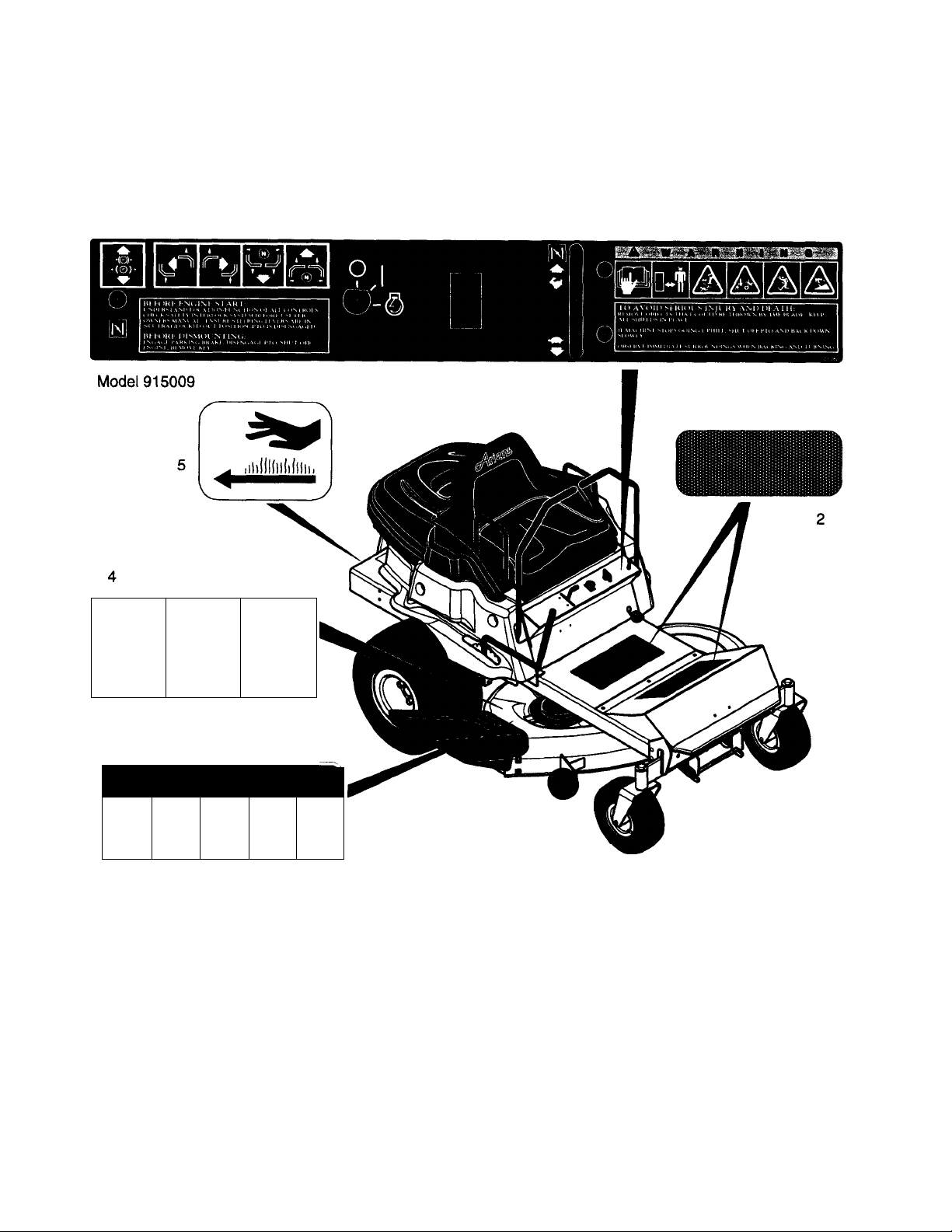
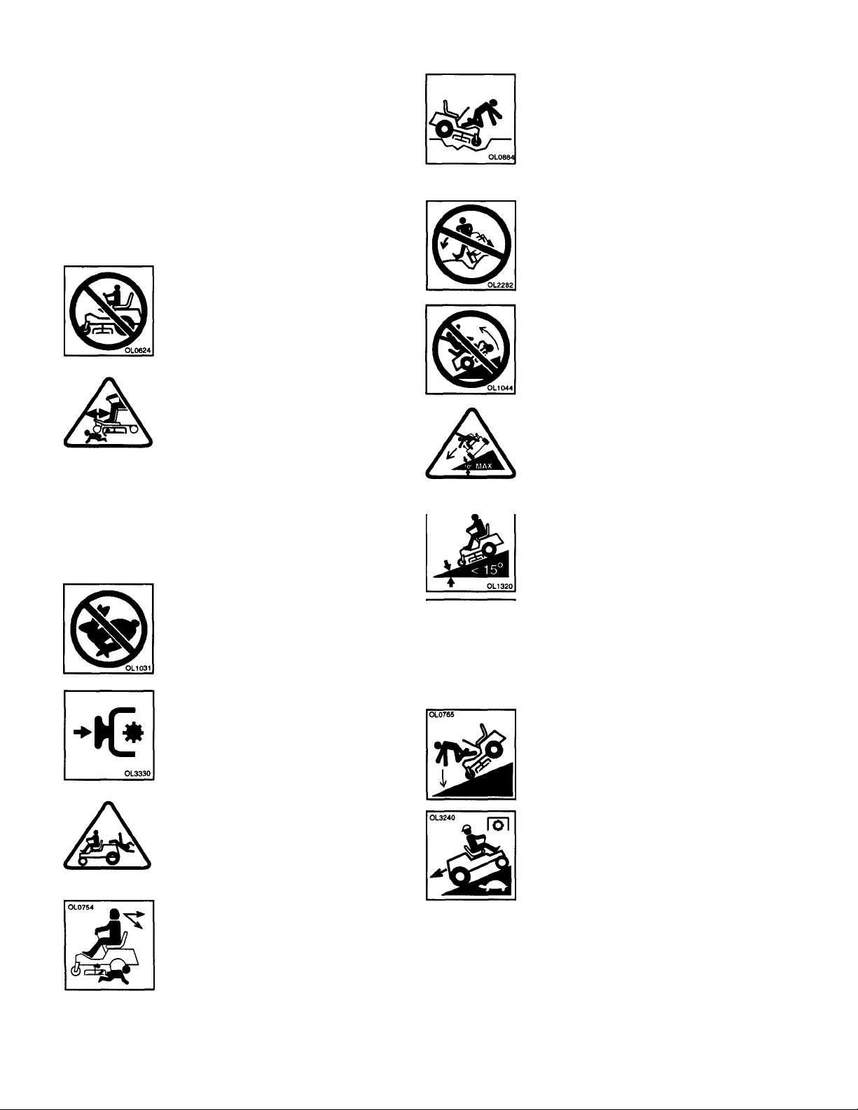
Safety Decals and Locations
ALWAYS replace missing or damaged Safety Decals.
Refer to Figure 2 for Safety Decal Locations.
Models 915008,010
A
II Jt
r ADANGER 1
3=^
V
____
D-t
«n*M J
1. WARNING Decal
2. Safety Tread Foot Board Cover
3. DANGER Rotating Blade
4. WARNING Guards
5. Hot Surface.
Ariens» EZRider™ Orig. 1/98
Figure 2
Page 8
Unit Safety
Walk Around Inspection
Complete a walk around inspection of
unit and work area to understand:
• Work area
• Your unit
• All safety decals
Clearances
ALWAYS check overhead and side
clearances carefully before operation.
Safety Guards and Devices
ALWAYS keep protective structures,
guards, and panels in good repair, in
place and securely fastened.
NEVER modify or remove safety
devices.
Discharge Covers
ALWAYS keep discharge cover or
complete grass catcher in place and
in proper working condition.
ALWAYS be aware of traffic when
operating along streets or curbs.
Work Area
Keep children and people away.
Keep children out of work area and
under watchful care of a responsible
adult.
Clear Work Area
Keep area of operation clear of all
toys, pets, and debris. Thrown objects
can cause injury.
Avoid Falls
Check for weak spots on dock, ramps
or floors. Avoid uneven work areas
and rough terrain.
Slippery Surfaces
Avoid siippery surfaces. ALWAYS be
sure of your footing.
Safety Interlock System
Safety Interlock System must function
properly. DO NOT operate unit if
operator presence controi is damaged
or disabled.
Modification
NEVER modify, alter, or permit
anyone to modify or alter the unit or
its components.
Brakes
Check brake operation frequently.
Adjust and service as required.
No Step
DO NOT step on rotary mower deck.
DO NOT operate on wet grass to
avoid siiding.
Visual Obstruction
Dust, smoke, fog, etc. can reduce
vision and cause an accident.
Operate unit only when there is good
visibility and light.
Safety Surfaces
Keep all nonskid surfaces clean.
Replace safety treads if worn,
damaged, or missing.
Ariense EZRider™ Rev. 1/97
Page 9
jLuaiü
Operational Safety
Rules of Operation
Understand:
• How to operate all controls
• The functions of all controls
• How to STOP in an Emergency
• Braking and steering characteristics
• Turning radius and clearance
Child Safety
NEVER allow children to operate, play
on or near unit.
Be alert and shut-off unit if children
enter area.
Pre-Start
Before starting engine: disengage
PTO, place unit in neutrai, lower
attachment, and set parking brake (if
applicable).
Avoid Tip over
Avoid uneven and rough terrain.
DO NOT operate near drop offs,
ditches, or embankments. Unit can
suddenly turn over if a wheel is over
the edge of a cliff or ditch, or if an
edge caves in.
DO NOT try to stabilize unit by putting
foot on ground.
Hazardous Slopes
DO NOT operate on steep slopes.
Operate up and down slopes, not
across slopes.
DO NOT operate on side hill slope of
more than 10°.
DO NOT operate on a downhill slope
of more than 15°.
AVOID starting and stopping on a
slope.
Speed Ranges
DO NOT operate at too fast a rate.
DO NOT change engine governor
settings or over speed engine. Slow
down and turn corners slowly.
PTO Control
Disengage PTO when attachment is
not in use. ALWAYS turn off power to
attachment when transporting,
crossing drives, etc.
No Riders
NEVER carry passengers.
Reverse
DO NOT operate in reverse uniess
absolutely necessary. ALWAYS
backup slowly. ALWAYS look down
and behind, before and while backing.
Keep all movement on slopes slow
and gradual. Use a slow speed to
avoid stops or shifts on slopes.
DO NOT make sudden changes in
speed or direction.
Traction
DO NOT turn on slopes unless
necessary, and then, turn slowly and
gradually down the slope.
If tires lose traction, turn off PTO, and
proceed slowly straight down slope.
If you cannot back up the slope or feel
uneasy, DO NOT mow it.
Ariens» EZRider’“ Rev. 1/97
Page 10

fol
OL0663
St
STOP
Shut-Off
ALWAYS disengage PTO, stop unit
and engine, remove key and allow
moving parts to stop.
Engage parking brake before leaving
operator’s position.
OL0220
Abnormal Vibrations, Foreign Objects, Clogged Unit
Immediately shut off unit.
INSPECT for any damage or loose
parts and repair before restart.
Parking
NEVER leave a running unit
unattended. ALWAYS shut off engine
before leaving unit.
ALWAYS remove key to prevent
unauthorized use.
Personal Safety
Responsible Operators
• Only trained adults may operate unit
• Training includes actual operation
No Drugs or Alcohol
NEVER operate unit after or during
the use of medication, drugs or
alcohol. Safe operation requires your
complete and unimpaired attention at
all times.
NEVER allow anyone to operate this
unit when their alertness or
coordination is impaired.
Safety Gear
Wear adequate safety gear,
protective gloves and footwear.
OL
NEVER wear open sandals or canvas
shoes during operation.
Unit Roli-Away
DO NOT park unit on a slope unless
absolutely necessary. When parking
on a slope always cock or block the
wheels. ALWAYS set parking brake.
Protect eyes, face and head from
objects that may be thrown from unit.
>L
Wear appropriate hearing protection.
a
Avoid Sharp Edges
Sharp edges can cut. Movement of
parts can cut off fingers or a hand.
Wrap blade(s), wear gloves and use
extreme caution when servicing.
IMPORTANT: On multi-blade
mowers, rotation of one blade will
cause all blades to rotate.
Avoid Rotating Parts
ALWAYS keep hands and feet away
from all rotating parts during
operation. Rotating parts can cut off
body parts
Ariens® EZRider™ Rev. 1/97
Page 11

Avoid Pinch Points
ALWAYS keep hands away from all
pinch points.
Maintenance and
Service Safety
^ r»i no
.0100 -
Avoid Hot Surfaces
DO NOT touch unit parts which might
be hot from operation. Allow parts to
cool before attempting to maintain,
adjust or service.
Avoid Entangiement
NEVER place your hands or any part
of your body or clothing inside or near
any moving part while unit is running.
DO NOT wear loose clothing or
jewelry and tie back hair that may get
caught in rotating parts.
Safe Distances
Keep children and people away from
unit during operation.
Avoid Thrown Objects
Deflected materials can cause injury
and property damage. DO NOT point
discharge at anyone or discharge
directly onto paved or gravel surfaces.
Always stand clear of the discharge
area when operating this unit.
loi
OL0863
B
0)
St
If*.
■ i* f
STOP
0
OL1410
Prepare Unit
Before making any inspections,
repairs, etc.: disengage PTO, stop
unit and engine, remove key, allow
moving parts to stop.
Allow hot parts to cool.
Service Position
ALWAYS block wheels and know all
jack stands are strong and secure
and will hold weight of unit during
maintenance.
Expiosive Fuei
Fuel is highly flammable and its
vapors are explosive. Handle with
care. Use an approved fuel container.
No smoking. No sparks. No flames.
ALWAYS allow engine to cool before
servicing.
NEVER fill fuel tank when engine is
running or hot from operation.
NEVER fill or drain fuel tank indoors.
Replace fuel cap securely and clean
up spilled fuel.
Avoid Exhaust Fumes
Fumes from engine exhaust can
cause injury or death.
Ventiiation
DO NOT run engine in an enclosed
area. Always provide good ventilation
and wait until hazard has been
removed.
Ariens» EZRider'“ Rev. 1/97
Replacement Parts
ALWAYS maintain unit in safe
operating condition. Damaged or
worn out muffler can cause fire or
explosion.
Hardware
Keep hardware, especially blade
attachment bolts, tight.
Page 12

Battery
Avoid Electric Shock. DO NOT
reverse battery connections.
Explosive Gases!
Poisonous battery fluid contains
sulfuric acid and its contact with skin,
eyes, or clothing can cause severe
burns.
Transport
NEVER push or pull (tow) unit with
another vehicle. Transmission
damage will occur.
Use extra care when loading or
unloading unit onto trailer or truck.
Block wheels and secure unit chassis
to transport vehicle. NEVER secure
from rods or linkages that could be
damaged.
0
0
QUÛ&Q
No flames. No sparks. No smoking
near battery. ALWAYS wear safety
glasses and protective gear near
battery.
______
DO NOT TIP battery beyond a 45°
angle in any direction.
ALWAYS keep batteries out of reach
of children.
Hydraulics
HYDRAULIC FLUID WILL CAUSE
SEVERE BURNS. Fluid in the
hydraulic system can penetrate the
skin and cause death or serious
injury.
Cleaning
Keep unit free of grass, leaves, or
other debris. Clean up oil or fuel spills.
DO NOT transport machine while
engine is running.
Attachments and
Accessories
Use only attachments or accessories
designed for your unit.
Check attachment components
frequently. If worn or damaged,
replace with manufacturer’s
recommended parts.
Avoid Tipover
Use extra care with grass catchers
and other attachments. These can
change the stability of the unit. Use
only approved hitch points.
Clearances
ALWAYS be aware of attachments
when turning. ALWAYS allow
adequate clearance between
attachments, personnel, and other
objects.
DO NOT transport with attachment in
the lowered (operating) position
Storage
For unit storage or extended storage:
• NEVER store with fuel in fuel tank,
inside a building where any ignition
sources are present
• Allow engine to cool completely
A
ALWAYS lower attachment when unit
is parked or stored.
Load Capacity
Know the weight of loads. Limit loads
to those you can safely control and
the unit can safely handle.
Ariens® EZRider'" Rev. 1/97
Page 13

SECTION 3
Operation
Controls and Features
See Figure 3 for Controls and Features locations.
Travel-Steering Control Levers
The Travel-Steering Control Levers are used to star,
stop, steer and control the travel direction of the unit.
Neutral Lock
To start, lock unit in neutral by pushing
both Travel-Steering Control Levers
outward -to each side- from centered
(neutral) position (Figure 4).
Straight Forward
Push the Travel-Steering Control Levers
SLOWLY forward the same distance from
the centered (neutral) position. The further
you move the levers, the faster the unit will
travel forward. (Travel-Steering Control
Levers have quick response timing.)
Straight Backwards (Reverse)
Pull the Travel-Steering Control Levers
back the same distance from the centered
(neutral) position. The further you move the
levers, the faster the unit will travel in
reverse.
Turns
Move one Travel-Steering Control Lever forward and
the other backward. Pushing the lever forward from the
centered position moves the unit forward on that side;
pulling the lever back from the centered position moves
the unit backward on that side.
1. Left Lever further forward that Right
Lever: turns unit to the right.
2. Right Lever further forward that Left
Lever: turns unit to the left.
Throttle Lever
(Also Choke Lever on 1540 models)
The Throttle Lever is used to change the speed of the
engine.
^ ^ Moving the lever to the “FAST” position
increases the engine speed.
Moving the lever to the “SLOW”
position decreases engine speed.
Ignition Switch
The Ignition Switch is operated with a
removable key. The switch may be
turned clockwise from the “OFF”
position to the “START” position then
the key will spring back to the “RUN"
position.
“OFF” Position: Ignition system is shut down.
“RUN” Position: All controls are operable.
“START” Position: Starter turns over the engine.
To start the engine the key must be in the “START”
position. To stop the engine, turn the key to the “OFF”
position.
Choke Control
N
1648 Modeis: The engine is choked by pulling Choke
control out to “CHOKE" position.
1540 Modeis: The engine is choked by moving the
Throttle Lever to the “CHOKE” position.
Parking Brake
To engage the Parking Brake, lift up on
knob and pull forward until it stops.
To disengage Parking Brake, lift up on
knob and push backward until it stops.
If one or both of the rear wheels do not
turn easily, check brake to assure it is
disengaged.
NOTE: Engine will shut off if control levers are taken
out of neutral with brake engaged.
Ariens» EZRider" Orig. 1/98
Page 14

1. Operator’s Seat
2. Travel-Steering Control Levers
3. Battery Compartment
4. Choke Control (1648 Models)
5. Ignition Switch
6. PTC Switch
7. Throttle Lever (also Choke
Control for 1540 Models)
8. Parking Brake Knob
9. Mower Deck Attachment Lift Lever
10. Foot Rest
11. Anti-Scalp Rollers
12. Mower Deck Attachment
13. Discharge Chute
14. Engine Shroud Cover
Figure 3
10
Ariens» EZRider™ Orig. 1/98
Page 15

Neutral Lock Position
Figure 4
Power Take Off (PTO) Switch
The Power Take Off Switch is used to engage and
disengage the attachment.
---------
When the PTO Switch is pulled out, it is in
the “ON” position and the attachment is
^ engaged.
When the PTO Switch is pushed in, it is in
^ the “OFF” position and the attachment is
disengaged.
Transmission Dump Vaives
Closing the Dump Valves allows the unit to by pushed
by hand. Dump Valves must be open to drive unit.
IMPORTANT: NEVER push or pull (tow) the unit with
another vehicle. Use a truck or trailer when transporting
or transmission damage can occur.
To Open the Dump Valves: Lift up on the Dump Valve
Rod and pull rearward until the expanded section of the
rod comes through the hole in the trailer hitch. Push the
rod back down to lock it into position (Figure 5).
To Close the Dump Valves: Lift up on the Dump Valve
Rod and push it back fon/vard.
1. Dump Valve Rod
2. Trailer Hitch
Figure 5
Pre-Start
Attachment Lift Lever
To raise the attachment, move the lever to
iWl'Ih the right to unlock It and pull up on lever.
I|||X To lower the attachment, move the lever to
the right to unlock It and push lever down.
Maximum cutting height is 5"; lowest cutting height is
1.38". Intermediate positions allow selection of cutting
heights between these values.
Safety interiock System
The engine must shut off if the operator leaves the seat
while the Travel-Speed Control Levers are In any
position other than the “NEUTRAL LOCK” position and
the PTO Switch is in the “ON” position.
Check Tires
Before each use, make a visual check of tires.
Check Engine Oil
Check that the engine oil is at proper level using
dipstick. Fill or change per instructions in General
Maintenance.
Check Seat Adjustment
Be sure all controls can be reached safely from
operator’s position. If seat needs adjustment, refer to
Adjustments.
Test Operation of All Controls
A CAUTION
Check function of all controls before starting engine.
All safety devices and guards must be in position
and operating properly or injury may result.
Ariens* EZRider'“ Orig. 1/98
11
Page 16

Starting and Shut-Off
See Figure 3 for Controls and Features Locations.
Starting
1. The operator must be seated.
2. Travel-Steering Control levers must be in the
“NEUTRAL LOCK” position (Figure 4).
3. The PTO Switch must be in the “OFF" position.
4. If the engine is cold, apply choke. See Engine
Manual for detailed instructions.
5. Set Throttle to proper starting position (see Engine
Manual).
6. Turn the ignition switch key clockwise to the
“START” position. Release the key when the
engine starts.
7. As soon as the engine starts, adjust choke as
needed. Wait until the engine is running smoothly
before operating the unit.
Shut-Off
1. With both Travel-Steering Control Levers pulled
back to centered (neutral) position, bring unit to a
complete stop on level ground.
2. Put PTO in the “OFF” position.
3. Move the Throttle Lever to “SLOW”.
4. Turn the Ignition Key to “OFF”.
5. Engage the Parking Brake.
Operation
See Figure 3 for Controls and Features Locations.
NOTE: This unit is equipped with an internal
combustion engine. DO NOT use equipment on or near
any unimproved, forest-covered or brush-covered land
unless exhaust system is equipped with a spark
arrestor meeting applicable local, state or federal laws.
A spark arrestor, if it is used, must be maintained in
effective working order by operator.
Speed
DO NOT operate and too fast a rate.
Sudden forward or backward movement in TravelSteering Control Lever(s) and fast speeds can
cause injury or death.
Move one or both Travel-Steering Control Lever(s)
forward and backward SLOWLY until you learn how to
operate the unit properly. The further you move the
levers, the faster the unit will travel.
NOTE: This unit is designed to be highly
maneuverable and responds quickly to movement of
the Travel-Steering Control Levers. Practice operation
of the controls in a flat open area until you are
comfortable with their operation. ALWAYS start and
backup slowly and make turns with caution.
Mowing
To mow with the unit:
1. Adjust deck to desired height.
2. Move Throttle Lever to about half speed.
3. Pull the PTO Switch to the “ON” position to engage
the mower.
4. Move the Throttle Lever fon/vard to full engine
speed.
5. Move Travel-Steering Control Levers forward to
mow.
IMPORTANT: NEVER engage the PTO if the mower is
plugged with grass or other material. This may cause
damage to the PTO Belt.
12
Ariens® EZRider™ Orig. 1/98
Page 17

Parking
MACHINE ROLL AWAY can cause injury or death.
ALWAYS engage Parking Brake when leaving unit
unattended.
Stop engine and remove key before cleaning or
servicing unit.
To park, stop the unit and engage the Parking Brake.
Always take all possible precautions when leaving unit
unattended.
Mowing Tips
The following tips will help you to mow safely, achieve
maximum performance from you unit and maintain the
desired appearance of your lawn.
NOTE: Clean mower pan after each use. DO NOT
allow grass clumps or a coating of grass and debris to
collect inside of mower pan. Avoid operation over bare
ground intermittent with grass cutting as this causes
dirt and grass to collect and cake under pan surface.
Grass should be cut when it si dry, not when it is wet
from dew, rain or watering. Wet grass tends to pack
inside mower pan and will not discharge, mulch or bag
properly, especially if height of cut is set too low.
Keep mower blades sharp. Dull blades will tear grass
and a white cast will result over a freshly cut lawn. The
tips of the grass blades will then turn brown.
A new lawn has soft blades of grass and a high
moisture content. It is important to cut a new lawn with
sharp blades.
Proper leveling and pitch of the rotary mower pan is
needed for a smooth even lawn. If the pitch of the
mower pan is reversed or inadequate, grass will be cut
twice, resulting in frayed grass ends. Too much pitch
will cause an uneven cut.
Upon first use of mower, cut the grass at a longer
length than usual. This will prevent scalping due to the
irregularities in the lawn.
To insure the most complete and even cut, overlap
each swath.
Plan your cutting so that you always trim with the left
side of the mower pan.
Following the same pattern each time you mow the
lawn can develope ridges. Change direction in mowing
pattern (when possible) to prevent ridges.
Generally, grass should be cut at about 1-1/2” long in
the spring and not less than 2” long in the hot summer
weather.
Lower unit speed at turns to prevent scuffing.
If grass is high, or if it contains a high degree of
moisture, cut it first with the mower pan set high. Cut
the grass a second time, with the mower pan set lower,
for a better distribution of clippings and a cleaner cut.
For thick, lush or heavy growth lawns do not set the
cutting height too low. Grass cut too short may die.
When the mower pan is set too low, the mower pan will
drag on the grass and restrict air flow, causing a
reduction in the discharge of grass clippings.
Discharge grass clippings away from borderline objects
(sidewalks, driveways, fences) when cutting grass.
Discharge grass clippings over cut grass when not
cutting borderlines. This will prevent buildup of grass
clippings on uncut areas.
Adjust Anti-Scalp Rollers properly for smooth
appearance in cut (see Adjustments).
Mow with engine set a full throttle to maintain proper
blade speed and air flow for discharge of clippings.
NOTE: Grass catcher components are subject to wear,
damage and deterioration which could expose moving
parts or allow objects to be thrown. Frequently check
components and replace with manufacturer’s
recommended parts when necessary.
Ariens» EZRider™ Orig. 1/98
13
Page 18

SECTION 4
<A
General Maintenance
Ariens Dealers will provide any service which may be
required to keep your unit operating at peak efficiency.
Should engine service be required, it can be obtained
from an Ariens Dealer or an authorized engine
manufacturer’s service center.
ALWAYS turn PTO Switch “OFF”, place TravelSteering Control Levers in “NEUTRAL LOCK”
position, set Parking Brake, turn ignition switch
“OFF”, wait for moving parts to stop, and remove
wire from spark plug before any maintenance or
adjustment.
Service Position
Place the unit on a flat, level surface. ALWAYS stop
engine and disengage PTO. Assure unit is secure and
will not tip over. Strap and clamp onto lift if used.
A CAUTION
3. Tilt seat forward.
4. Clean the fuel cap and the area around the fuel cap
to prevent dirt from entering the fuel tank (Figure
6).
Remove enough fuel so that no spillage will occur.
DO NOT touch engine or drive parts which are hot
from operation. Allow such parts to cool before
servicing.
Fuel Tank
Fuei is highly flammable and its vapors are
expiosive. Handle with care.
NO smoking, NO sparks, NO flames.
Add fuel to the fuel tank as needed. See the Engine
Manuai for the correct type and grade of fuel.
To add fuel to the fuel tank:
1. ALWAYS place unit in open or well ventilated area.
2. Stop engine and allow to cool for 2 minutes.
5. Remove the cap from the fuel tank.
6. Fill the fuel tank. Use care; do not spill fuel.
7. Replace the cap on the fuel tank and tighten.
8. ALWAYS clean up any spilled fuel before staring
engine.
9. Lower Seat.
Hardware
Keep all nut, bolts and screws tight and be sure
equipment is in safe working condition. Check all
hardware at regular intervals.
14
Ariens« EZRider™ Orig. 1/98
Page 19

Engine
Correct maintenance can increase the life of the
engine. See Engine Manual for information on the
operation and maintenance of the engine.
IMPORTANT: DO NOT change engine governor
setting or over speed engine.
To access engine;
1. Flip seat forward.
2. Unhook Engine Shroud Cover latch.
3. Push in on clips located under seat and lift Cover
up and off unit. Place aside (Figure 6).
4. After engine service is complete, replace and
fasten Engine Shroud Cover.
Engine Cooling
Each day before operation, every 12 hours, or more
often if conditions require, check the following:
1. Check the level of oil in the engine. NEVER
operate the engine when oil level is below the add
mark.
2. Check air cleaner element. Dirt can decrease the
flow of air to the engine.
3. Check the air cooling system on the engine. Debris
can decrease the flow of air to the engine.
IMPORTANT: DO NOT operate engine with cooling
fins plugged or removed; this will cause overheating
and engine damage.
Engine Oil
IMPORTANT: DO NOT over fill. Oil level must not
exceed Full (F) mark. Overheating and engine damage
will occur. Be sure engine is level when adding oil.
7. Replace oil cap and dipstick.
8. Clean up any spilled oil.
Change Engine Oil
To drain engine crankcase oil:
1. Open the valve, located on the left side of the
engine at the back of the unit. The oil will drain
through a tube under the back of the frame.
2. Close valve when drained.
Belts
MOVING PARTS can cut or amputate body parts.
ALWAYS wait for moving parts to stop before
maintenance or service of unit.
Mower Drive Beit Replacement
Refer to Figure 7.
1. Disconnect main idler spring from frame.
2. Remove belt from electric clutch and mower pan.
3. Install new belt in reverse order, checking for belt
alignment and clearance.
4. Connect main idler spring to frame.
Check and Add Engine Oil
The engine crankcase oil should be checked daily or
every 5 hours of operation. Oil level MUST be
maintained in safe operating range on dipstick at all
times or engine damage will result (see Engine
Manual).
To Check Engine Crankcase Oil;
1. Park unit on a flat, level surface. Place TravelSteering Control Levers in neutral and set brake.
2. Stop engine and remove Engine Shroud Cover.
3. Clean debris away from oil cap.
4. Remove oil cap and dipstick. Wipe oil off dipstick
with a clean cloth. Replace dipstick until cap
bottoms on tube.
5. Remove dipstick again and observe oil level. Oil
should be at the Full (F) mark.
6. If low, add oil at oil fill opening and bring oil level up
to the Full (F) mark.
Ariense EZRider“ Orig. 1/98
Rotary Mower Belt Replacement
Refer to Figure 7.
1. Remove mower drive belt.
2. Remove sheave covers.
3. Remove idler spring.
4. Remove belt.
5. Reverse procedure for installation.
Transaxle Belt Replacement
1. Remove transaxle idler spring from frame.
2. Remove belt from belt from transaxles (Figure 8).
3. Remove belt from engine sheave.
4. Install new belt in reverse order, checking for belt
alignment and clearance.
5. Connect transaxle idler spring.
15
Page 20

Clutch Shaft Belt Replacement
1. Remove transaxle belt (Figure 8).
2. Remove clutch shaft idler spring from frame.
3. Remove belt from engine sheave.
4. Remove belt from clutch sheave.
5. Install new belt in reverse order, checking for belt
alignment and clearance.
5. Connect clutch Idler spring to frame.
6. Reinstall transaxle belt.
Lubrication
Apply a small amount of oil to the pivot points as
required for smooth and proper operation.
Grease the fittings on the front wheel spindles, the idler
arms, and the steering controls every 50 hours of
operation (Figures 8 and 9).
Apply astenMIx Hl-Temp Grease or equivalent to the
lube fittings. Order P/N: 00036800 - Three pack of 3
oz. cartridges or 00036700 - Ten pack of 14 oz.
cartridges.
1. Clutch Shaft Idler
2. Clutch Shaft Belt
3. Transaxle Idler
4. Transaxle Belt
5. Idler Springs
6. Mower Drive Belt
7. Mower Drive Idler
8. Main Idler Spring
Figure 8
16
Figure 9
OE0031
OE0192
Ariens« EZRider™ Orig. 1/98
Page 21

Tire Pressure
Before each use, make a visual check of tires. The
correct air pressure is 10-12 psi (65-83 kN/m^).
Battery
Hydraulics and Transaxles
HYDRAULIC FLUID WILL CAUSE SEVERE
BURNS. Fluid in the hydraulic system can penetrate
the skin and cause serious injury or death.
Keep body and hands away from pin holes or
nozzles which expel hydraulic fluid when under
pressure. Use paper or cardboard and not hands to
search for leaks.
Make sure all hydraulic fluid connections are tight
and all hydraulic hoses and lines are in good
condition before applying pressure to the system.
Foreign fluid injected into the skin must be surgically
removed within a few hours by a doctor familiar with
this form of injury or gangrene may result.
Transaxle Fluid
The transaxle fluid is a lifetime oil which need not be
changed over the unit life.
Sharpening Mower Blades
ELECTRIC SHOCK may result in injury and/or
damage to unit.
DO NOT allow objects to come into contact with
both terminals at the same time.
REVERSE CONNECTIONS may result in sparks
which can cause serious injury. ALWAYS connect
positive (+) lead of charger to positive (+) terminal,
and negative (-) lead to negative (-) terminal.
ALWAYS connect positive (+) cable FIRST, and
negative (-) cable SECOND.
EXPLOSIVE GASES from battery can cause death
or serious injury. ALWAYS keep open flames,
sparks, or smoking materials away from batteries.
POISONOUS BATTERY FLUID contains sulfuric
acid and its contact with skin, eyes, or clothing can
cause severe chemical burns. ALWAYS wear safety
glasses and protective gear near battery.
DO NOT TIP any battery beyond a 45° angle in any
direction.
ALWAYS KEEP BATTERIES OUT OF REACH of
children.
ACAUTION
MOVING PARTS AND SHARP BLADES can cut or
amputate body parts.
ALWAYS use sturdy gloves or padding to protect
hands when working with mower blades.
1. Shut off the engine and unit. Remove the ignition
key. Remove the ignition wire from the spark plug.
2. Remove the locknuts, flat washers, and blades
from the spindle shafts.
3. Sharpen the beveled edges of the blades in a
straight line. DO NOT change the angle of the
beveled edge. If more than 0.5 inch (12.7 mm) are
removed from the width of a blade, discard the
used blade. Make sure the sharpened blades are
balanced. Balance must be held within 1.3 in. oz.
4. Put the blades, washers, and locknuts back on the
spindle shafts.
5. Tighten lock nuts to a torque of 60 ft. lbs. (82 Nm).
6. Put the ignition wire back on the spark plug.
Battery Electrolyte First Aid
Follow First Aid directions for contact with battery fluid.
• External Contact: Flush with water.
• Eyes: Flush with water for at least 15 minutes
and get medical attention immediately!
• Internal Contact: Drink large quantities of water.
Follow with Milk of Magnesia, beaten egg or
vegetable oil. Get medical attention immediately!
IMPORTANT: In case of internal contact, DO NOT
induce vomiting.
Ariens® EZRider™ Orig. 1/98
17
Page 22

Battery Removal
Remove battery from unit before servicing (Figure 10).
To remove the battery from the unit:
1. Remove the four screws at the front of the seat
support; use a 7/16” wrench.
2. Pull the control panel forward.
3. Remove wing nut from the Battery Rod and remove
the rod.
4. Disconnect the negative (-) cable first.
5. Disconnect the positive (+) cable second.
6. Lift the battery out of the unit and place battery on
a bench or other well ventilated area where an acid
spill will not create damage.
When service is finished, reinstall battery into unit and
connect positive (+) cable first, then negative (-) cable.
Electrolyte Level
Every 25 hours or each week, check the electrolyte
level of each cell by removing caps one at a time. The
electrolyte level should be at level indicator. Use
distilled water to fill each cell if needed.
IMPORTANT: When distilled water is added to battery
during freezing weather, it must be charged to mix
water with electrolyte or water will remain at top and
freeze.
Battery Charger
Under normal conditions the engine alternator will have
no trouble keeping the battery charged. When unit has
not been operated for an extended period of time and
the battery has been completely discharged, a battery
charger will be required for recharging.
Before using a charger, an attempt can be made to
recharge the battery using the engine alternator by
jump starting the unit and allowing the engine to run.
Charging
FROZEN BATTERIES CAN EXPLODE and result in
death or serious injury.
DO NOT charge a frozen battery. Let the battery
thaw out before putting on a charger.
ALWAYS follow information provided on battery by
battery manufacturer. Contact battery manufacturer for
extensive instructions to charge battery.
To charge:
1. Remove battery from unit per removal instructions
above.
2. Remove caps and fill each cell to level indicated
with electrolyte at 1.230 ± specific gravity and 80° F
(27° C).
3. Let battery stand for one half hour.
4. Check electrolyte level and add more if necessary.
5. Connect positive (+) lead of charger to positive (+)
terminal of battery.
6. Connect negative (-) lead of charger to negative (-)
terminal of battery.
7. Charge the battery at two and a half amps for ten
hours or until all cells are gassing freely and the
specific gravity is constant over three 30 minute
intervals.
8. Immediately after charging, check electrolyte level.
If low, add distilled water to bring cell(s) up to
required level.
9. Reinstall battery into unit and connect positive (+)
cable first, then negative (-) cable.
18
Ariens® EZRider™ Orig. 1/98
Page 23

Jump Starting
Jump starting, battery charging or replacement is
required when the starter motor will not crank the
engine.
To jump start engine:
1. Ensure battery is not frozen. If the fluid is frozen,
remove battery from unit and allow it to thaw before
charging.
2. The unit used for jump starting should have a 12
volt battery with at least 500 cold cranking amperes
and a negatively grounded system.
UNIT MOVEMENT can result in death or serious
injury. NEVER jump start unit directly to the starter
or starter solenoid. Unit can move forward or
backward and injure the person jump starting unit.
3. Connect the positive (+) jumper cable to the
positive terminal of the discharged battery.
4. Connect the other end of the same jumper cable to
the positive (+) terminal of the booster battery.
5. Connect one end of the second jumper cable to the
negative (-) terminal of the booster battery.
6. Make the final jumper cable connection to the
engine block or the furthest ground point away from
the discharged battery.
7. Follow Starting and Shut-Off steps in Operation
section.
8. Remove jumper cables in the reverse order of their
connection. Remove cable from: the ground point,
then the negative (-) terminal of the booster battery,
then the positive (+) terminal of the booster battery,
and finally the positive (+) terminal of the
discharged battery.
Adjustments
Ahens recommends that adjustments be made by the
Ariens dealer. Should the decision be made to make
the following adjustments on the unit yourself, Ariens
recommends calling the dealer for answers to any
questions that might arise.
Neutral Adjustment (Speed Control Lever)
1. Stop the engine. Remove the ignition key. Push the
PTO knob in the “OFF” position.
A CAUTION
PREVENT personal injury! ALWAYS KNOW that
jack(s) or blocks used are stable, strong and will
support the weight of the unit.
Place jack(s) under rear transaxles only. If jack(s)
are not available, place support blocks under both
transaxles at the rear of unit.
Raise the rear drive wheels off the floor. Remove
3.
side shrouds. Place aside for replacement.
Start the engine and run it at part throttle.
Loosen the two lock nuts holding the Speed
Control Arm (Figure 11).
Turn and loosen the connection to the Speed
Control Arm with the Flange Bushing untii the
wheel stops rotating.
Lock the Speed Control Arm in place by tightening
the two lock nuts.
8. Repeat procedure for other side of unit.
Ariens® EZRider™ Orig. 1/98
19
Page 24

Parking Brake Adjustment
There are two knob positions for the Parking Brake.
“ON" or Engaged - Pull the knob up and fonward.
“OFF” or Disengaged - Pull the knob up and push
backward.
To adjust the “ON” position:
1. Pull the Parking Brake knob up in the travel slot
until the nut on the rod can pass through the
keyway. The knob can now be pulled forward.
2. Turn the nut on the rod threads until the rod can
not move backward when it is dropped in the travel
slot. The rod will now stay in the “ON” or Engaged
position.
Seat Adjustment
Lift up and tilt seat fonvard to locate seat adjustment
screws on the seat plate. Loosen the two front and two
back screws that hold the rear springs. Slide operator
seat forward or rearward as desired. Retighten screws
as required.
Mower Level (Side to Side)
NOTE: A wood block (about 1" square by 5“ long) may
be used under pan for blade measurement. Wrap block
with masking tape, mark tape with cutting edge of
blade and measure distance from end of block to
mark(s). (This method avoids errors by having to read
any measurements under pan.)
To Check Side to Side Level:
1. Position unit on a smooth, flat, level surface. Set
tire pressure properly.
2. Position blade(s) side to side, measure distance of
blade tips to floor at right and left side of mower
pan (Figure 12). Rotate blade(s) 180° and check
again. The measurement should be equal within
1/8" side to side.
To Adjust Side to Side Level:
1. Loosen nut on height adjuster (Figure 13).
2. Turn height adjuster nut clockwise on low side of
mower pan to raise low side one half the difference
in height. Turn height adjuster nut counterclockwise
on high side to lower high side the other one half of
the height difference.
20
Ariens® EZRider™ Orig. 1/98
Page 25

Mower Pitch
Proper blade pitch is when the blade tip, measured
from the bottom surface, is 1/8" to 1/4" lower at front of
mower pan than when same tip is at rear of mower pan
(Figure 14).
Front of Unit
TTTT
— 4
Anti-Scalp Rollers
Secure rollers in top position for average lawn mowing.
Use lowest roller position when mowing in higher
cutting height or rough terrain to guard against most
scalping. Use top roller position when cutting at lowest
cutting height.
For a smooth appearance, cut lawn using frame
suspended models with anti-scalp rollers. Keep anti
scalp roller adjusted to the minimum 1/2” above flat,
hard, smooth surface.
NOTE: Rollers are intended for anti-scalping, not for
controlling cutting height.
1. Cutting Edges
2. Ground Level
3. Front Blade Height
4. Rear Blade Height
Figure 14
To Adjust pitch loosen flange lock nuts and slide
adjusting tabs up or down to achieve proper pitch
(Figure 13).
Mower Height
Adjusting hanger hooks equally raises or lowers the
mower pan and changes cutting height.
To adjust:
1. Loosen upper nuts on hanger hooks and turn lower
nuts equally clockwise to lower or counterclockwise
to raise rear of rotary mower. With mower
attachment lift in highest position, front blade height
should measure 5" from ground level.
2. Secure hanger hooks by tightening nuts.
Mower Belt
The mower belt idler system Is designed to provide
constant tension on the belt.
Transport
Equipment should be shut off when transporting. To
move unit without the engine running, open the Dump
Valves (refer to Controls and Features). Close the
Dump Valves before operating.
IMPORTANT: NEVER push or pull (tow) the unit with
another vehicle. Use a truck or trailer when transporting
or transmission damage can occur.
Cleaning and Storage
IMPORTANT: NEVER spray unit with water or store
unit outdoors to aid in prevention of rust or corrosion.
Water can seep into sealed bearings, which are sealed
against dirt and debris only, causing reduced
component life.
Keep all nuts, bolts and screws tight and be sure
equipment is in safe working condition. Check all
hardware at regular intervals.
Never store equipment with fuel in tank inside a
building where fumes may reach an open flame or
spark. Allow engine to cool before storing in any
enclosure.
Ariens» EZRider™ Orig. 1/98
21
Page 26

EZRider Specifications
Model
Engine
15 HP Briggs&Stratton 16 HP Briggs&Stratton
Model Number
Type
Speed
Fuel Tank Capacity
Crankcase Capacity 56 oz. (1.66 liters)
Fuel Type
Lubricant Type
915008
28P777-0647E1
915009 915010
303777-114281
OHV
3250 rpm
3.5 gals. US (13.3 liters)
4 pts. (1.9 liters)
See Engine Manual
See Engine Manual
Tires
Rear
Front
Pressure (all tires)
18 X 8.50-8 4 ply rating
11.0x4.00-5
10to12psi (83 to103kN/m*)
Hydrostatic System
Lubricant Type
20W-50
Speeds @ 3200 rpm
Fon/vard
Reverse
0 to 5.7 mph (9.1 km/hr)
0 to 4.1 mph (6.6 km/hr)
Speeds @ 2900 rpm
Forward
0 to 5.2 mph (8.4 km/hr)
Reverse 0 to 3.6 mph (5.8 km/hr)
Length
Width
Height
Weight
52 in (132 cm) 60 in (152.4 cm) 52 in (132 cm)
588 ibs. (267 kg)
71.88 in (182.5 cm)
44.7 in (113.5 cm)
628 Ibs. (385kg) 588 Ibs. (267 kg)
15 HP Kohler
PS-41531
64 oz. (1.89 liters)
22
Arlense EZRider'“ Orig. 1/98
Page 27

QUALITY
QUALITY
PRODUCTS
Ariens will be fre^
PROTECTION PLAN
• The Company will provide for the replacement of any part found upon examination by the Company to be
defective. Such repair or replacement will be free of charge to the purchaser (labor and parts) for two years
LABOR
w
PUKCHASKD
*WEAR
(24 months) from the date of purchase. Ariens manufactured parts (but not labor) will be free of charge for
an additional three years (36 months) thereafter.
PURCHASER RESPONSIBLITIES
• Maintenance & minor adjustments per owners manual
• Notification of need for warranty service
• Transportation to/from place of warranty repair
PRODUCT REGISTRATION
• Return of registration card required to validate warranty
PURCHASED COMPONENTS & NORMAL WEAR
• Two year labor and parts on purchased components
i.e., (tractor drive train components manufactured by
Dana, Eaton, Foote, Sundstrand and any plastic and
electrical components, wire harness, bags, boots, tubes,
etc.).
• Two year labor and parts on normal wear items i.e.,
(belts and rubber components, bearings, cables,
controls, clutches, tines, etc.).
BATTERY WARRANTY PRORATED
• One to six months - free replacement
• Seven to twelve months - 50% credit
• Thirteen to twenty-four months - 25% credit
WARRANTY- COMMERCIAL PRODUCTS
• One year parts and labor
• Product labeled commercial/professional
• Household use - 5 year limited warranty applies
GUARANTEE
ÎARS FROM
This warranty is subject to the following exceptions and limitations:
RENTAL USE-ALL PRODUCTS
• NINETY DAYS LABOR & PARTS
CONSUMER PRODUCT - PUT TO COMMERCIAL,
INDUSTRIAL, INSTITUTIONAL USE
• NINETY DAYS LABOR & PARTS
SERVICE PARTS & ACCESSORIES
• NINETY DAYS LABOR & PARTS
SERVICE
For warranty service, contact any Ariens Distributor
or Dealer. For the name and location of the Ariens
Distributor or Dealers in your area, and for further
warranty information, write or call Ariens Company.
ENGINES, ENGINE ACCESSORIES, & PEERLESS
PRODUCTS
• Covered only by manufacturer’s warranty
EXCLUSIONS
• No warranty is extended to blades, mower vanes, skid
shoes, runners, scraper blades, shear bolts, light bulbs,
headlights and any equipment which has been altered,
misused, misassembled, improperly adjusted,
neglected, or damaged by accident.
• No warranty is extended for service completed by
anyone other than an authorized distributor or dealer.
• No warranty is extended on any parts that are not
genuine Ariens service parts.
• Ariens Company reserves the right to incorporate
any changes in design into its products without
obligation to make such changes on products
previously manufactured.
A
&
PARTS
c4lcns.
Crafted in
Amarica
Since 1933
DISCLAIMER OF FURTHER WARRANTY
There is no other express warranty. Implied warranties, including
any warranty of merchantability or fitness for a particular purpose,
are limited to the duration of this written warranty, and are excluded
to the extent permitted by law. There are no warranties which extend
beyond the description of the product contained herein.
In no event shall the company be liable for indirect, special or
consequential damages (such as loss of anticipated profits)
in connection with the consumer's use of the product.
This warranty gives you specific legal rights, and you may also have
other rights which vary from state to state. Some states do not allow
the exclusion of incidental or consequential damages, or limitations
on how long an implied warranty lasts, so the above limitation and
exclusions may not apply to you.
OL1243 9/97
Page 28

(T^lens
655 West Ryan Street • RO. Box 157 • Brillion, Wl 54110-0157 • 920-756-2141 • Fax 920-756-4421
Ask Your Dealer For Information On
These Other Fine Ariens Products
• Front and Rear Tine Tillers
• Walk-Behind Lawn Mowers
• Zero-Turning Radius Mowers
• Rear Engine Riding Mowers
• Yard and Garden Tractors
• Commercial Walk-Behind and Riding Mowers
• Sno-Thros
 Loading...