

Page 1

A SAFETY MESSAGE A
The product for which you have requested
information or repiacement parts is not a
current product. The repiacement modeis
incorporate product designs, safety features,
safety instructions or warnings which repre
sent the latest “State Of The Art” develop
ments. For your safety and those around you
please contact your nearest Ariens/Gravely
Dealer for a demonstration of the current
product safety provisions and features.
■
.^M
■
lens
Sno-Thro
Owner/Operator Manual
MODELS
006 - SS322 007 - SS522 008 - SS322E
009 - SS522E 301 - SS322 303 - SS522
038076 Orig.4/96
Printed in USA
Page 2

<^4tens
Thank You
Ariens outdoor power equipment is
engineered to be the best from start to
finish. We have one fundamental belief:
Value is not measured solely by price;
value is a durable, easy-to-use machine
that performs season after season.
This manual and the engine manual are
your guides. By following the instructions
and procedures in them, your Ariens
equipment will serve you well for many
years. The care you give this equipment
will determine your overall satisfaction and
its service life.
Safety is up to you. Obey all correct
operating practices and procedures for
this equipment. Prevent serious injury or
death. Three reasons safety is important:
1. Accidents disable and kill.
Your Satisfaction Is Important
Questions? Please follow these helpful steps:
1. Always Refer to Your Owner/Operator or
Engine Manual First.
a) Its detail will guide you through safe and
proper operation and maintenance.
b) It contains specifications on your model of
equipment.
c) If your questions are not answered in these
manuals, go to step number two.
2. Contact Your Ariens Dealer.
a) Our dealers will be happy to supply any
service or advice required to keep your
equipment operating at peak efficiency.
b) A factory trained staff is available to
support your equipment needs. They stock
genuine Ariens parts and lubricants;
manufactured with the same precision and
skill as the original equipment.
c) If your questions are not resolved by the
support staff, ask for the manager or owner.
d) When contacting your Ariens Dealer supply
your equipment or attachment model and
serial numbers.
______________________
2. Accidents can be avoided.
3. Accidents always cost.
Ariens proudly offers one of the finest
warranties in the business. Contact your
Ariens Dealer with any questions,
comments or orders. Ariens equipment for
the world is made in the USA.
Crafted in
America
Since 1933
The engine exhaust from this product
contains chemicals known to the State of
California to cause cancer, birth defects or
other reproductive harm.
Page 3

Table of Contents
o4rlenst
Section
Page
Section 1: Introduction
The Manual
Service and Replacement Parts
Product Registration........................................1
Disclaimer..........................................................1
Section 2: Safety
Safety Alert Symbol
Signal Words
Practices and Laws...........................................2
Required Operator Training
Safety Decais and Locations
Personal Safety
Operational Safety.............................................5
Maintenance and Senrice Safety
Section 3: Assembly
Dealer Preparation
Delivery
Section 4: Operation
Standard Controls............................................10
Impeller
Impeller Clutch Bail..........................................10
Ignition Switch.................................................10
Primer Bulb......................................................10
Choke Control Knob
Recoil Starter Handle......................................10
Discharge Chute Deflector
Discharge Chute...............................................12
Pre-Start............................................................12
Starting and Shut Off
Controls and Features
Throwing Snow.................................................13
........................................................
......................
____________
..........................................
.....................................................
.............................
...........................
.................................................
.....................
_________
............................................
..............................................................
_________
.............................................................
.......................................
..............................
.......................................
.....................................
10
1
1
10
12
12
13
Section
Page
Section 5:
General Maintenance
Filling Fuel Tank..............................................14
Service Position
Engine Cooling................................................14
Clutch and Brake
Drive Belt
Discharge Chute Deflector.............................16
Transport..........................................................16
2
2
2
3
4
«t
6
_
y
7
9
№
100S
Storage.............................................................16
Accessories.....................................................16
Maintenance Schedule
Section 6: Specifications
Model................................................................18
Engine..............................................................18
Fuel ................................................................ 18
Electric Start Option
Snow Clearing Width
OL0700
Snow Throwing Distance
Chute................................................................18
Size and Weight
Handlebar.........................................................18
Impeller
Drive Belt
Wheels..............................................................18
Warranty...........................................................19
............................................................
..............................................
............................................
.........................................................
...................................
.......................................
......................................
..............................................
.........................................................
________
...............................
14
15
16
17
18
18
18
18
18
18
#
Ariense Sno-Thro* Orig. 4/96
Page 4

Sno-Thro Models
Model 938006 (SS322)
3 HP 22” Single Stage
Serial Number 000101 and up
Model 938007 (SS522)
5 HP 22” Single Stage
Serial Number 000101 and up
Model 938008 (SS322E)
3 HP 22" Single Stage, Electric Start
Serial Number 000101 and up
Model 938009 (SS522E)
5 HP 22” Single Stage, Electric Start
Serial Number 000101 and up
Model 938301 (SS322) Export
3 HP 22" Single Stage
Serial Number 000250 and up
Model 938303 (SS522) Export
5 HP 22” Single Stage
Serial Number 000101 and up
o
All rights rasarvad. No part of this publication may ba raproducad, transmittad,
O Copyright 1996 Arlant Company
transcribad, storad In a ratrlaval systam, or translatad Into any languaga In any form
by any maans without tha writtan parmisslon of Arlans Company
Prlntad In U.S.A.
o
Arl«iii» Snd'Thro* OHg. 4/96
Page 5
SECTION 1: INTRODUCTION
<?4
Contents
• The Manual
• Service and Replacement Parts
• Product Registration
• Disciaimer
Introduction
The Manual
Before you operate your unit, carefully
and completely read manuals supplied
with unit. The contents wili provide you
with an understanding of safety
instructions and controis during normai operation and
maintenance of your unit. Graphics are provided to heip
you understand the text.
Ail reference to left, right, front, or rear are given from
operator standing in operation position and facing the
direction of forward travei.
Transfer |
model & serial .
label from '
product I
registration .
here. I
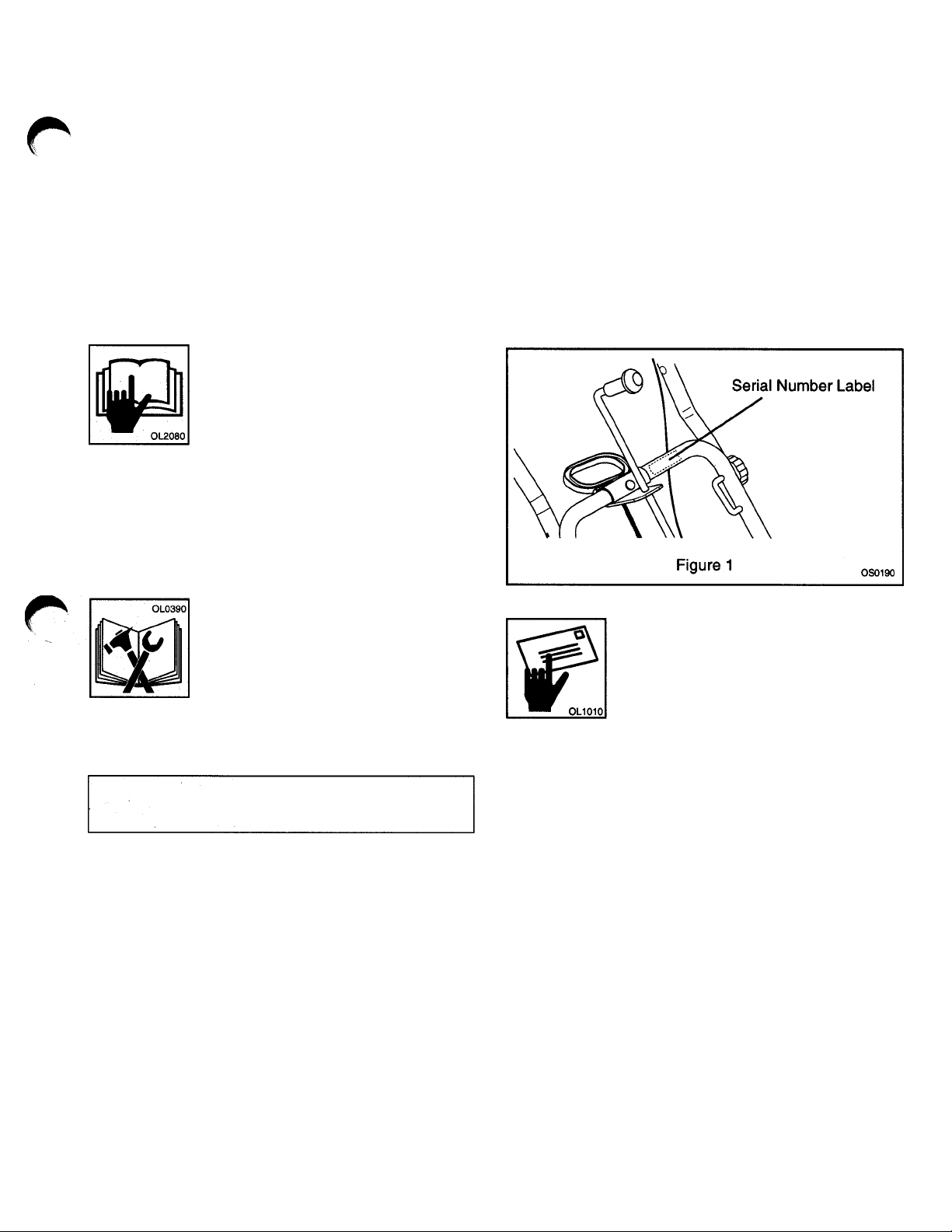
Service and
Replacement Parts
When ordering replacement parts or
making service inquiries, know the
Model and Serial numbers of your unit
and engine.
Record Unit Model and Serial numbers here.
Record Engine Model and Serial numbers here.
Numbers are located on the product registration form in
the unit Literature Package. They are printed on a Serial
Number Label (see Figure 1).
Product Registration
A warranty registration card must be
filled out by the Ariens dealer, signed,
and returned at sale. This form
activates the warranty. The replacement
of any part on this unit with anything other than an
Ariens authorized replacement part may adversely affect
the performance, durability, or safety of this unit and may
void the warranty. Claims meeting requirements during
limited warranty period will be honored. To guarantee
full warranty service, make sure your registration card
has been returned to Ariens Company.
Disclaimer
Ariens Company is hereinafter referred to as Ariens.
Ariens reserves the right to discontinue, make changes
to, and add improvements upon its products at any time
without public notice or obligation. Ariens disclaims
liability for any claims or damages, whether regarding
property, personal injury or death arising out of the use
of unauthorized replacement parts. The descriptions
and specifications contained in this manual were in
effect at printing. Equipment described within this
manual may not be identified as either standard or
optional. Illustrations may not be applicable to your unit.
Ariens® Sno-Thro® Orig. 4/96
Page 6

SECTION 2: SAFETY
<A
Contents
• Safety Alert Symbol
• Signal Words
• Practices and Laws
• Required Operator Training
Safety
• Safety Decals and Locations
• Personai Safety
• Operational Safety
• Maintenance and Service Safety
Safety Alert Symbol
This is a safety alert symbol. It means:
• ATTENTION!
A
• YOUR SAFETY IS INVOLVED!
When you see this symbol:
• BECOME ALERT!
• OBEY ITS MESSAGE!
Signal Words
The safety alert symbol is used with the following signal
words and colors to alert you to safety messages. They
are used in safety decals on the equipment and with
proper operation and procedures in this manual. They
alert you to the existence and relative degree of hazards.
Understand the safety message. It contains important
information about personal safety on or near the unit.
EXTREME HAZARD
Adanger
Awarning
ACAUTION •A'»!'"
For your safety and the safety of others read and
follow A DANGER, A WARNING, and A CAUTION
messages found in manuals and on safety decals.
• Avoid!
• ACT WILL RESULT in
serious injury or death.
HAZARD
• Avoid!
• ACT CAN RESULT in
serious injury or death.
POTENTIAL HAZARD
• ACT MAY RESULT in
injury.
Notations
NOTE : General reference information for proper
operation and maintenance practices.
IMPORTANT: Specific procedures or information
required to prevent damage to unit or attachment.
A WARNING
IMPROPER OPERATION of this
ft]. 1 f
_ •
hlTt
unit can result in serious injury or
death. Before starting the engine.
OL2080
OL1350
OL1021
follow these three steps:
1. Read and understand this
manual and all safety decals on
unit or attachment.
2. Keep children and people away
when operating unit.
3. Clear area before operation.
n
Practices and Laws
Practice usual and customary safe working precautions,
for the benefit of yourself and others. Understand and
follow all safety messages. Be alert to unsafe conditions
and the possibility of minor, moderate, or serious injury
or death.
Information in this manual does not replace any safety
rules and laws in your area. Before operating this unit,
learn all applicable rules and laws in your area.
Required Operator Training
Original purchaser of unit was instructed by seller on
safe and proper operation and use. If this unit is to be
used by someone other than original purchaser (loaned,
rented, sold) ALWAYS provide this manual and any
needed safety training before operation.
Ariens® Sno-Thro® Orig. 4/96
Page 7
P
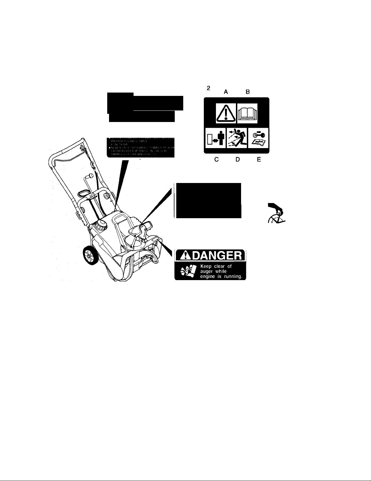
Safety Decals and Locations
ALWAYS replace missing or damaged Safety Decals.
Refer to Figure 2 for Safety Decal locations.
SAFETY
A
INSTRUCTIONS
TO AVOID POSSIBLE INJURY READ
OWNERS MANUAL AND UNDERSTAND
PURPOSE OF ALL SAFETY ALERTS.
1. SAFETY INSTRUCTIONS
2. SAFETY INSTRUCTIONS (938301,303)
A. Attention! Your safety is involved!
B. Read Owner/Operator Manual.
C. Keep people away from unit during
operation.
D. Always stand clear of discharge area
E. Shut off engine and remove key before
maintenance.
3. DANGER! Rotating Parts
A DANGER
I- ROTATING
PARTS
remove ignition
key before clearing
4. Safety Decal (938301,303)
A. Attention! Your safety is involved!
B. Read Owner/Operator Manual.
C. Keep hands away from rotating parts.
D. Shut off engine and remove key before
maintenance.
5. DANGER! Keep Clear of Auger
6. Safety Decal (938301,303)
A. Attention! Your safety is involved!
B. Read Owner/Operator Manual.
C. Keep feet away from rotating parts.
D. Shut off engine and remove key before
maintenance.
B
A
D
B
A
D
6
Ariens® Sno-Thro® Orig. 4/96
Figure 2
Page 8

Personal Safety
Responsible Operators
• Only trained adults may operate
unit
• Training includes actual operation
• Clearly understand instructions
• Be alert! Conditions can change
No Drugs
NEVER operate unit after or during
consumption of medication, drugs or
alcohol. Safe operation requires
complete and unimpaired attention at
all times.
No Alcohol
NEVER aliow anyone to operate unit
when their alertness or coordination is
impaired.
Safety Gear
Wear safety gear to protect body.
DO NOT wear loose clothing or jeweiry
that may get caught in rotating parts.
Wear adequate winter outer garments.
Rotating Parts
Movement of Impeller and other parts
can cut off body parts. Keep away from
rotating parts while parts are in motion.
Hot Surfaces
DO NOT touch parts which might be hot
from operation. Before maintenance,
adjustments or service, allow parts to
cool.
Avoid Pinch Points
ALWAYS keep hands away from all
pinch points.
Exhaust Fumes
Fumes from engine exhaust can cause
injury or death.
Gloves
Wear gloves to protect hands from
sharp edges.
Protective Footwear
NEVER wear open sandals or canvas
shoes during operation. Wear footwear
that will improve footing on slippery
surfaces.
Safety Goggles
Wear safety goggles to protect eyes
from thrown objects.
Entanglement
NEVER place hands, body parts or
clothing inside or near any moving
parts.
mL/
y . OL054C
0
OL1410
Ventilation
DO NOT run engine in enclosed area.
ALWAYS provide good ventilation and
wait until hazard has been removed.
Explosive Fuel
Fuel is highly flammable and its vapors
are explosive. Handle with care. Use
an approved (RED) fuel container.
Fuel Tank
No smoking. No sparks. No flames.
ALWAYS allow engine to cool.
NEVER fill tank when engine is running
or hot from operation.
NEVER Fill Fuel Tank indoors. Fill fuel
tank outdoors from approved (RED) fuel
container.
Replace Fuel Cap securely and wipe up
spilled fuel.
Ariens® Sno-Thro® Orig. 4/96
Page 9

r
Operational Safety
Rules of Operation
KNOW Unit before starting engine.
Understand;
Child Safety
Keep children out of work area and
under watchful care of an adult.
c
OL0340
• How to operate all controls
• Functions of all controls
• How to STOP in an Emergency
• Braking & steering characteristics
• Turning radius and clearances
Speed Ranges
DO NOT clear snow at too fast a rate.
DO NOT change engine governor
setting or over speed engine.
Walk Around Inspection
Complete a walk around inspection of
unit and work area to understand:
• Area of operation
• Your unit
• All safety decals
Visual Obstruction
Dust, smoke, fog, etc. can reduce
vision and cause an accident. Operate
equipment only with good visibility and
light.
n
Hazardous Slopes
DO NOT attempt to operate on steep
slopes.
Use Extreme caution on slopes.
Unit Roll-Away
DO NOT park unit on an incline and
leave unit unattended.
Clearances
ALWAYS check overhead and side
clearances carefully before operation.
Clearly mark potential obstructions
before seasonal changes.
ALWAYS be aware of traffic when
operating along streets or curbs. Set up
safety signs and/or flags.
OL1021
A
Clear Area
Keep area of operation clear of all toys,
pets, doormats, wire and debris to
avoid thrown objects which may result
in injury.
Work Area
ALWAYS be sure of your footing. Avoid
slippery surfaces. Walk; NEVER run.
Tip Over
DO NOT operate near drop offs,
ditches or embankments. Unit can
suddenly turn over if a wheel is over
the edge of a cliff or ditch, or if an edge
caves in. Avoid uneven and rough
terrain.
Safe Distances
Keep people away from unit during
operation.
Ariens® Sno-Thro® Orig. 4/96
Thrown Objects
Deflected materials can cause injury
and property damage. DO NOT
discharge directly onto paved or gravel
surfaces.
Discharge Area
ALWAYS stand clear of discharge area
during operation.
ALWAYS position Discharge Chute and
Deflector in safe direction and angle
before starting engine. ALWAYS
provide a safe, secure area for material
being discharged.
Page 10

\
OL0866
s
STOP
Clearing Debris & Blockages
ALWAYS disengage Impeller, stop
engine, remove key and wait for all
moving parts to stop before you: leave
operators position, unclog unit, make
repairs or adjustments or inspections.
Check for and repair any damage
before restart.
Run unit a few minutes after throwing
snow to prevent freeze-up of Impeller.
Electric Starter
Use only approved extension cords and
receptacles when starting units
equipped with Electric Starter.
Si
K.0610
_________
Engine
Before maintenance, adjustments or
service (except where specifically
recommended):
Shut off engine
^
Allow engine to cool
Transport
Disengage Impeller, and shut off engine
when unit is being transported.
Ol
Si
KJ
STOP
02»
OL0870
Maintenance and
Service Safety
Abnormal Vibrations
Stop unit and engine immediately,
remove key and wait for all moving
parts to stop. Check for and repair any
damage before restart. Check for and
tighten any loose hardware before
restart.
Parking
Never leave a running unit unattended.
ALWAYS shut off engine.
ALWAYS remove key to prevent
unauthorized use when unit is not in
operation.
Safety Devices
NEVER operate unit without guards
and other safety devices in place and
functional.
Check Clutch and Brake function
frequently as instructed in Assembly
Section.
Storage
NEVER store unit, with fuel in fuel tank,
inside a building where ignition sources
(pilot lights, hot water or space heaters,
clothes dryers, etc.) are present.
Allow engine to cool before storage in
any enclosure.
If storing for an extended period, clean
unit thoroughly and see Engine Manual
for proper storage.
Ariens* Sno-Thro* Orig. 4/96
Page 11

SECTION 3: ASSEMBLY
Contents
• Dealer Preparation
• Delivery
Assembly
Dealer Preparation
Customer Note - Your Ariens Dealer is expected to
complete these preparation steps and review important
information, including this manual, with .you before or
upon delivery of unit or attachment.
The preparation information is included here so that you
and your dealer may review it together.
TW
ÜmRNING
ELECTRIC SHOCK can result in
serious injury or death and/or damage
to equipment.
>
Tools Required
Open-end wrench: 7/16"
DO NOT remove wire from spark plug
while engine is running.
Handlebar
1 Unit is in handlebar “fold” position for shipping
(Figure 3).
2. Keep customer in mind and adjust Upper Handle
Bar higher or lower by selecting alternate holes for
“J” bolts (Figure 4).
3. Unfold Upper Handlebar.
4. Tighten Knobs to secure Upper Handlebar in
place.
Package Contents
Literature Package and Ariens Sno-Thro (Figure 3).
f
Ariens® Sno-Thro® Orig. 4/96
Page 12

Discharge Chute Crank (938006,009)
To install Discharge Chute Crank (Figure 6);
9. Remove Nut from bolt that holds Recoil Starter
Handle Bracket in place.
10. Pull the Chute Crank Assembly up so hole in
Chute Crank Bracket fits behind/under Lower
Handle Bar and over bolt end.
NOTE: DO NOT pull Chute Crank Assembly up too far.
If Chute Crank Bracket goes past Lower Handle Bar,
48T Gear and Spacer will fall off into unit.
11. With Crank Knob straight up and Discharge Chute
straight forward, check that 48T Gear meshes with
12T Pinion at Space and Tooth Identification
Marks. Align if necessary.
6. Remove Rear Cap Screw and Nut from rear of
Discharge Chute (Figure 5).
7. Tip Discharge Chute up and install hardware just
removed.
8. Tighten hardware at rear of Discharge Chute first,
then at sides.
1.
Nut
2.
Recoil Starter Handle Bracket
3.
Chute Crank Shaft
4.
Crank Knob
5.
Chute Crank Bracket
6.
Lower Handle Bar
7.
Space & Tooth Identification Marks
Spacer
8.
9.
48T Gear
10. 12T Pinion
11. Cotter Pin
Figure 6
Ariens» Sno-Thro» Orig. 4/96
Page 13

12. Insert Cotter Pin (taped to Chute Crank Assembly)
through 48T Gear and Chute Crank Shaft. Minor
movement of the Crank Shaft or Discharge Chute
Handle may be needed to align holes.
13. Rotate Chute Crank to access Cotter Pin and
secure Pin by bending ends over.
14. Reinstali Nut, securing Chute Crank and Starter
Handie Brackets to Lower Handle Bar.
№
Engine Fuel
A WARNING
Hardware
21. Check for loose hardware.
Walk Around Inspection
22. Walk around unit and check for leaking, damaged,
or missing parts. Make necessary repairs before
operation.
Clutch and Brake
A WARNING
UNIT ROLL AWAY can result in serious injury or
death. Check and test Clutch and Brake before
each operation.
EXPLOSIVE VAPORS and
FLAMMABLE FUEL can result in
serious injury or death. Handle fuel
with care. ALWAYS Use an
approved (RED) fuel container.
No Smoking!
0
0
0
IMPORTANT: 2 cycle engines require that oil be mixed
with fuei. Failure to mix oil with gasoiine will result in
seizure and severe damage to engine. DO NOT use
gasohol or gasoline containing alcohol because alcohol
will cause internal parts to deteriorate. See Engine
Manual for Correct type and grade of fuel.
No Lighted Materials!
No Open Flame!
Allow engine to cool before servicing.
OL1410
15. Put unit in open area.
16. Clean Fuel Cap and area around
Fuel Cap to prevent dirt form
entering Fuel Tank. Remove Cap.
23. Ensure there is some slight, noticeable slack in the
Control Cable Inner Wire when Impeller Clutch Bail
is disengaged (released position). Bail should travel
6-3/4 to 7-1/4" (17.1-18.4 cm) before Handlebar
contact.
24. Ensure there is a noticeable increase in resistance
1 to 1-1/2“ (2.5-3.8 cm) before Impeller Clutch Bail
contacts Handlebar.
25. Check that Impeller stops within 5 seconds after
releasing Impeller Clutch Bail.
Delivery
Using the Owner/Operator Manual, instruct customer on
controls and operation of equipment. Emphasize safety
and discuss Safety Precautions. Give customer
Owner/Operator Manual. Advise customer to thoroughly
read and understand it.
Explain recommended lubrication and maintenance of
equipment. Advise customer on adjustments.
Fill out Original Purchaser Registration Card and return
to Ariens. Place Model and Serial Number on page in
the front of this manual.
17. Mix 50 parts fuel to 1 part oil.
№+i
OStW Mix 2 Cycle Engine
Lubricant is recommended.
soQi
18. Fill fuel tank with mixture. Tank capacity is 1.2
quarts (1.1 liters).
NOTE: Fuel mixture left standing for prolonged periods
wili begin to separate; thoroughly shake mixture before
using.
19. Replace Fuel Cap and tighten.
20. ALWAYS clean up any spilled fuel.
Ariens® Sno-Thro® Orig. 4/96
Warranty
Explain Ariens Limited Warranty Policy.
Page 14

SECTION 4: OPERATION
<t4
Contents
• Standard Controls
• Pre-Start
Operation
• Starting and Shut Off
• Controls and Features
' Throwing Snow
Standard Controls
See Figure 9 for Control and Feature locations.
Impeller
During snow removal, Impeller propels unit forward while
collecting snow. Forward speed will vary according to
snow depth and moisture content.
Impeller Clutch Bail
Squeeze Impeller Clutch Bail against
Handlebar to engage Impeller. Unit will
move fonward and throw snow. Release
Bail to disengage and brake Impeller
IMPORTANT: Check impeiler to be sure it
is not frozen. If belt squeals when Clutch
Bail is engaged. Impeller is frozen.
Release Clutch Bail and move equipment
to a heated area to thaw.
IMPORTANT: Check Clutch/Brake
function before each use. If Impeller does
not stop quickly when Impeller Clutch Bail
is released or there is no noticeable
increase in Bail force before contacting
Handlebar, adjust as directed in
Maintenance Section, or repair before
operating unit.
Choke Control Knob
When pulled out (away from Impeller
Housing), Choke Control Knob chokes off
air to engine for easier start. When pushed
in. Control Knob allows for normal
operation.
IMPORTANT: ALWAYS push Control Knob in (towards
Impeller Housing) after engine start.
Recoil Starter Handle
When pulied. Recoil Starter Handle will turn engine over.
Ignition Switch
See Figures 7 and 8.
Ignition Switch is operated by a removable Key. It has
two positions:
^ "Stop" Position
(2) Run Position
Primer Bulb
Push Primer Bulb in to add fuel for easier
engine start (Figure 8).
10
Ariens® Sno-Thro® Orig. 4/96
Page 15

1. Impeller Clutch Bail
Chute Crank (938007,009)
2.
Recoil Starter Handle
3.
4. Handlebar Knob
Chute Deflector Handle
5.
6. Air Intake ^
Chute Deflector
7.
8.
Discharge Chute
Impeller Housing
9.
Impeller
10.
Scraper Blade
11.
12. Discharge Chute Rotation Handle
Fuel Tank and Cap
13.
14. Cowl
Impeller Control Cable
15.
Figure 9
Ariens* Sno-Thro* Orig. 4/96
11
Page 16

Discharge Chute Deflector
ALWAYS position Discharge Chute Defiector in safe
direction and angie before starting engine. Use Handle
at rear of Defiector to position Defiector at desired
height. DO NOT throw snow any higher than necessary.
IMPORTANT: If Chute Deflector does not stay in set
position, adjust as directed in Maintenance Section, or
repair before operating equipment.
Discharge Chute
Discharge Chute rotates 220°. Rotate Chute with
Deflector Chute Handle or crank chute with Defiector
Chute Handie ON Models 938007,009 only. (Figure 10)
IMPORTANT: DO NOT force frozen Chute controls.
Start engine and run for 3-5 minutes to thaw. If still
frozen, take to warm place until controls are free.
Starting and Shut Off
Starting
1. Turn discharge chute straight ahead.
2. Push Primer Bulb 2 or 3 times for cold engine.
NOTE: When temperature is below -15° F additional
priming may be needed.
3. Pull choke control out to "Choke" position (Figure 7).
NOTE: A warm engine requires less choking than a cold
engine.
4. Insert Key into Ignition Switch.
5. Turn key to run position.
6. Grasp starter handle and pull rope out slowly until it
pulls harder, this is compression stroke, let rope
rewind slowly (Figure 8).
7. Pull rope with a rapid continuous full arm stroke. Let
rope rewind slowly.
IMPORTANT: DO NOT let Starter Handle snap against
Starter Handle Bracket.
8. Repeat until engine starts. (If engine does not start,
refer to Engine Manual.)
9. When engine has started, open Choke slowly by
gradually pushing Choke Control in.
Pre-Start
IMPORTANT: Before engine start check Impeller to be
sure it is not frozen. With key in "Stop" position,
squeeze Impeller Clutch Bail to Engaged position and
pull Recoil Starter Handle. If Impeller is frozen, (cannot
pull Starter Handle) move unit to a heated area and thaw
to prevent possible damage.
Shut Off
1. Run Impeller a few minutes after use to prevent
freeze-up of Impeller.
2. Release Impeller Clutch Bail and allow Impeller to
stop.
3. Turn Ignition Switch to "Off" position.
4 Remove key.
12
Ariens® Sno-Thro® Orig. 4/96
Page 17

1. Switch Box
2. Starter Button
3. Female End of Power Cord
Figure 11
Controls and Features
Electric Starter
Optional on models 938006, 007, 301,303 (Figure 11).
IMPORTANT: Electric starter is not equipped with a
thermal cutout switch. DO NOT crank engine for more
than 20 seconds. Always allow electric starter to cool
down for 10 minutes or electric starter damage will
result.
1. Follow Starting and Shut Off steps 1 -5.
2. Connect female end of power cord to Switch Box.
3. Plug male end of power cord into 120 volt AC
receptacle.
4. Push Starter Button to crank engine.
5. When engine starts, release Starter Button and
, disconnect Power Cord from receptacle first, then
from Switch Box.
6. Gradually push in choke control knob to housing.
Throwing Snow
Lift the Handlebar only high enough to propel unit
forward. Do not lift so high to allow snow to kick back
from under unit.
To clear an area, run unit in an overlapping
series of paths. For large areas start in
middle and throw snow to each side so you
do not have to move snow more than once.
ALWAYS direct snow away from area to be
cleared and with direction of wind.
Ariens* Sno-Thro* Orig. 4/96
13
Page 18

SECTION 5: GENERAL MAINTENANCE
<т4
Contents
• Filling Fuel Tank
• Service Position
• Engine Cooling
• Clutch & Brake
• Drive Belt
• Chute Deflector
Transport
Storage
’ Engine Trouble Shooting
General Maintenance
• Maintenance Schedule
• Accessories
Ariens Dealers will provide any service which may be
required to keep your unit operating at peak efficiency.
Should engine service be required, it can be obtained
from an Ariens dealer or an authorized engine
manufacturer's service center.
Ш
Filling Fuel Tank
A WARNING
EXPLOSIVE VAPORS and
FLAMMABLE FUEL can result in
serious injury or death. Handle fuel with
care. ALWAYS use an approved (RED)
fuel container.
No Smoking!
0
0
1. Add fuel to Fuel Tank as needed.
2. Put unit in open or well ventilated area.
IMPORTANT: 2 cycle engines require that oil be mixed
with fuel. Failure to mix oil with gasoline will result in
seizure and severe damage to engine. DO NOT use
gasohol or gasoline containing alcohol because alcohol
will cause internal parts to deteriorate. See Engine
Manual for correct type and grade of fuel.
Ш+4
50Э1
No Lighted Materials!
No Open Flame!
«
OL1410
OLU10 Allow engine to cool before maintenance.
3. Stop engine and allow to cool.
4. Clean Fuel Cap and surrounding area
to prevent dirt form entering Fuel Tank.
5. Remove Cap.
Mix 50 parts fuel to 1 part oil. We
6.
recommend OSten Mix a 2 Cycle
Engine Lubricant.
Fill fuel tank with mixture. Tank
OL0840
7.
capacity is 1.2 quarts (1.1 liters).
NOTE; Fuel mixture left standing for prolonged periods
will begin to separate; thoroughly shake mixture before
use.
8. Replace Fuel Cap and tighten.
9. ALWAYS clean up any spilled fuel.
Service Position
Tip unit forward onto front of Impeller housing for
service. Assure unit is secure and will not tip over. Strap
and clamp onto bench if needed.
A CAUTION
When equipment is tipped up onto housing, remove
enough fuel so that no spillage will occur.
Engine Cooling
Engine is air cooled. Air must circulate freely around
engine from Air Intake (Figure 12) to cooling fins on
cylinder head and block, to prevent overheat.
A WARNING
HOT SURFACES can result in
serious injury or death. DO NOT
touch parts which are hot from
operation. ALWAYS allow parts to
____________
Every 10 hours of operation or every year (more often if
conditions require) remove cooling shrouds and clean
cooling fins. Clean external surfaces of engine of dust,
dirt and oil deposits which can contribute to improper
cooling. See Engine Manual.
IMPORTANT: DO NOT operate engine with cooling
shrouds removed, this will overheat engine and cause
damage.
9L21S2.
cool.
14
Ariens® Sno-Thro* Orig. 4/96
Page 19

Clutch and Brake
Impeller Control Cable Adjustment
For Brake to function properly, there must ALWAYS be
some slight, noticeable slack in the Control Cable Inner
Wire when the Impeller Clutch Ball is disengaged
(lowered position). This allows Extension Spring to pull
Idler Arm/Brake, braking Belt. Bail should travel 6-3/4 to
7-1/4“ (17.1-18.4 cm) before contacting Handlebar. If
Brake does not stop Impeller within 5 seconds of
releasing Impeller Clutch Bail, Inner Wire slack must be
adjusted.
A properly adjusted Clutch must show a noticeable
increase in resistance (caused by stretch of Control
Cable Spring) before Impeller Clutch Bail contacts
Handlebar. At factory adjustment, increase occurs 1 to
1-1/2" (2.5-3.8 cm) from Handlebar. As Drive Belt seats
and wears, increase in resistance will occur closer to
Handlebar contact. If no resistance occurs. Inner Wire
slack must be adjusted.
To adjust Inner Wire (Figure 12);
• Use Adjusting Nuts on Control Cable to remove
almost all slack in Inner Wire.
IMPORTANT: If there is still no resistance, the Idler
Position must be adjusted.
NOTE: It may be desirable to leave extra slack in the
Control Cable Inner Wire so Bail resistance is not
uncomfortably strong when held up against the
Handlebar.
6. Start engine and ensure Impeller does not rotate
when Impeller Clutch is disengaged.
7. Repeat the above steps until proper adjustment is
achieved.
IMPORTANT: If adjustment cannot be achieved, the
Drive Belt must be replaced.
8. Replace Cowl.
1. Control Cable Inner Wire
2. Adjusting Nuts
#
Idler Position Adjustment
For proper operation, the Idler must be as close as
possible to the Drive Belt when the Impeller Clutch Bail
is disengaged (lowered position), but not so close that it
causes Impeller rotation. To adjust the Idler position
(Figure 13):
1. Shut off engine, allow to cool, and remove Cowl.
ROTATING PARTS can result in
serious injury or death. ALWAYS
keep hands and feet away. DO NOT
wear loose clothing or scarves that
may get caught in rotating parts.
2. Ensure Control Cable Inner Wire has slack when
Impeller Clutch Bail is disengaged (lowered
position).
3. Ensure Belt Fingers are properly adjusted (see
Drive Belt Replacement).
4. Loosen Idler hardware, reposition Idler along Slot in
Idler Arm, and tighten hardware.
5. Check for proper Impeller Clutch Bail resistance.
Figure 12
1.Extension Spring
2.Idler Arm/Brake
3.ldler
4.Slot
5.Belt Finger
B.Impeller Clutch Control Cable & Spring
7.Drive Belt
8.Impeller Drive Pulley
9.Cap Screw & Washer on Impeller Shaft
Ariens® Sno-Thro® Orig. 4/96
Figure 13
15
Page 20

Drive Belt
To replace drive belt (Figure 13):
1. Remove Cowl and disconnect Extension Spring on
Idler Arm/Brake.
2. Remove Cap Screw and Washer from end of
Impeller Shaft and pull off Impeller Drive Pulley.
Remove old Belt and install new one.
3.
4. Replace parts in reverse order checking to be sure
there is 1/32 to 1/16“ (1-1.6 mm) clearance
between Belt Finger and back side of Belt with
Impeller Clutch Bail engaged.
Discharge Chute Deflector
If Discharge Chute Deflector does not stay in set position
during operation adjust chute by:
• Tightening Fasteners evenly until Deflector stays in
position (Figure 14).
NOTE: Use a #T30 Torx Drive or a 3/16" (.19 cm) wide
Straight Screwdriver to tighten.
Storage
Run the unit with Impeller Clutch engaged a few minutes
after each use to free unit of any loose or melting snow.
Keep all nuts, bolts and screws tight and be sure unit is
in safe working condition. Check all hardware at regular
intervals.
Never store unit with fuel in tank inside a building where
fumes may reach an open flame or spark.
Allow engine to cool before storage in any enclosure.
Be sure to drain fuel or run the fuel tank dry before
storage.
It is possible to hang the unit on a wall.
Engine trouble shooting
PROBLEM
Probable Cause
Engine will not crank
Check if Key Switch is in run position
Check for a bad starter or connections.
Check for electrical problems.
Transport
Equipment should be shut off when transporting. To
transport equipment to or from an area to be cleared,
press down on handlebar enough to raise front of SnoThro slightly off surface and push or pull unit.
Engine will not start
Check for electrical problems.
Check for engine ignition problems - see Engine
Manufactures Service Manual.
Engine stops.
Check fuel supply. Use only clean fuel.
Check spark.
Engine power, noise, idle and shut down.
See Engine Manufactures Service Manual.
Accessories
737001 Electric Start (3 HP)
737002 Electric Start (3 HP)-Canada
738001 Electric Start (5HP)
16
Ariens® Sno-Thro® Orig. 4/96
Page 21

Maintenance Schedule
The chart below shows the recommended service
schedule that should be performed on a regular basis.
More frequent service may be required due to working
conditions (heavy loads, high ambient temperatures,
dusty conditions, airborne debris).
See Engine maintenance instructions in Engine Manual.
Page 22

SECTION 5: SPECIFICATIONS
<t4
Contents
• Specifications • Warranty
Specifications
Sno-Thro
Model Number 938006
938301 938303
Description SS322 SS522
Engine
Engine Power - HP (KW) - 2 Cycle
Engine Operating Fast Idle Speed - RPM 4300 3600 4300 3600
Engine Displacement - in (cc)
Fuel
Fuel to Oil Mix
Fuel Tank Capacity - qt (Liters)
Fuel Filter Neck Inside Dia. - in (cm)
120V Electric Start Option
Snow Clearing Width - Cu. in (cm)
Snow Throwing Distance - ft (meters)
Chute
Chute Rotation Angle
Chute Rotation Control at Handlebar No
Chute Inside Dia - in (cm)
Handlebar
Operator Present Impeller Clutch/Brake Control
Folding Handlebar
Handlebar Adjustable For Height
Size & Weight
Handlebars Max. Extended Height - in (cm)
Minimum Folded Height - in (cm)
-----------------------------------------------------X.
Length - in (cm)
Minimurn Folded Length - in (cm)
Width - in (cm)
Weight - lbs (Kg)
Impeller
Impeller Dia - in (cm)
Impeller Speed - RPM
Drive Belt
Single “V”
Construction
Material
Wheels
Wheel Size - in (cm)
----------^--------------------------------------------------
3 (2.24)
6.0 (98) 8.46(139)
1
58 (26.4) 73 (33.2)
1120
938007
5 (3.73)
See Engine Manual for type and grade
1.2 (1.1)
2.8 (7.1)
Yes
22 (56)
3-30 (0.9-9.1)
007Yes/303 No No
6.0(15.2)
40.8(104)
25.8 (65.5)
43.2(110)
34.5 (87.6)
22 (56)
9.0 (23)
1100
3L Section
Raw Edge
Kevlar Cord
7.0 X 1.5(18x3.8)
938008 938009
SS322E
3 (2.24) 5 (3.73)
6.0 (98) 8.46(139)
50:1
220°
Yes
Yes
Yes
60 (27.2)
1120
Yes
1 75 (38.5) 1
1 1100 1
SS522E
Installed |
Yes
18
Ariens® Sno-Thro® Orig. 4/96
Page 23

QUALITY
QUALITY
PRODUCTS
GUARANTEE
Aricn& Company hereby warrants to Uie original consumer purchaser that products nunufactuied
by Ai iciix ('on)pun> will Iv free from defects in material and woi kmanship TOR A PERIOD
OF i 1\ E t5) YT \RS FROM THE DATE OF PURCHASE, LX( T.PT AS NOTED BELOW.
PROTECTION PLAN
• The Company will provide for the replacement of any part found upon examination by the Company to be
2^
LAB OR
defective. Such repair or replacement will be free of charge to the purchaser (labor and parts) for two years
(24 months) from the date of purchase. Ariens manufactured parts (but not labor) will be free of charge for
an additional three years (36 months) thereafter.
This warranty is subject to the following exceptions and limitations:
PURCHASER RESPONSIBLITIES RENTAL USE - ALL PRODUCTS
• Maintenances: minor adjustments per owners manual • NINETY DAYS LABOR & PARTS
• Notification of need for warranty service
• TransDortation to/from olace of warrantv reoair ^
PRODUCT REGISTRATION
• Return of registration card required to validate warranty
PURCHASED COMPONENTS & NORMAL WEAR
• Two year labor and parts on purchased components
i.e., (tractor drive train components manufactured by
Dana, Eaton, Foote, Sundstrand and any plastic and
electrical components, wire harness, bags, boots, tubes,
etc.).
• Two year labor and parts on normal wear items i.e.,
(belts and rubber components, bearings, cables,
controls, clutches, tines, etc.).
BATTERY WARRANTY PRORATED
• One to six months - free replacement
• Seven to twelve months - 50% credit
• Thirteen to twenty-four months - 25% credit
WARRANTY- COMMERCIAL PRODUCTS
• One year parts and labor
• Product labeled commercial/professional
• Household use - 5 year limited warranty applies
„ . ,A. , t . CONSUMER PRODUCT-PUT TO COMMERCIAL,
• NINETY DAYS LABOR & PARTS
SERVICE PARTS & ACCESSORIES
• NINETY DAYS LABOR & PARTS
SERVICE
• For warranty service, contact any Ariens Distributer
or Dealer. For the name and location of the Ariens
Distributer or Dealers in your area, and for further
warranty information, write or call Ariens Company.
ENGINES, ENGINE ACCESSORIES, & PEERLESS
PRODUCTS
• Covered only by manufacturer’s warranty
EXCLUSIONS
• No warranty is extended to blades, mower vanes, skid
shoes, runners, scraper blades, shear bolts, light bulbs,
headlights and any equipment which has been altered,
misused, misassembled, improperly adjusted,
neglected, or damaged by accident.
• No warranty is extended for service completed by
anyone other than an authorized distributor or dealer.
• No warranty is extended on any parts that are not
genuine Ariens service parts.
• Ariens Company reserves the right to incorporate
any changes in design into its products without
obligation to make such changes on products
previously manufactured.
A
s
PAR TS
«PA RTS
Crafted In
America
Since 1933
#
DISCLAIMER OF FURTHER WARRANTY
There is no other express warrsnty. Implied warranties, including
any warranty of merchantability or fitness for a particular purpose,
are limited to the duration of this written warranty, and are excluded
to the extent permitted by law. Thera are no warranties which extend
beyond the description of the product contained herein.
In no event shall the company be liable for indirect, special or
consequential damages (such as loss of anticipated profits)
Ariens® Sno-Thro® Orig. 4/96
in connection with the consumer's use of the product.
This warranty gives you specific legal rights, and you may also have
other rights which vary from state to state. Some states do not allow
the exclusion of incidental or consequential damages, or limitations
on how long an implied warranty lasts, so the above limitation and
exclusions may not apply to you.
19
Page 24

94leiì&
655 West Ryan Street • RO. Box 157 • Brillion, Wl 54110-0157 • 414-756-2141 • Fax 414-756-4421
Ask Your Dealer For Information On
These Other Fine Arlens Products
• Front and Rear Tine Tillers
• Walk-Behind Lawn Mowers
• Zero-Turning Radius Mowers
• Rear Engine Riding Mowers
• Yard and Garden Tractors
• Commercial Waik-Behind and Riding Mowers
• Sno-Thros
 Loading...