

Page 1
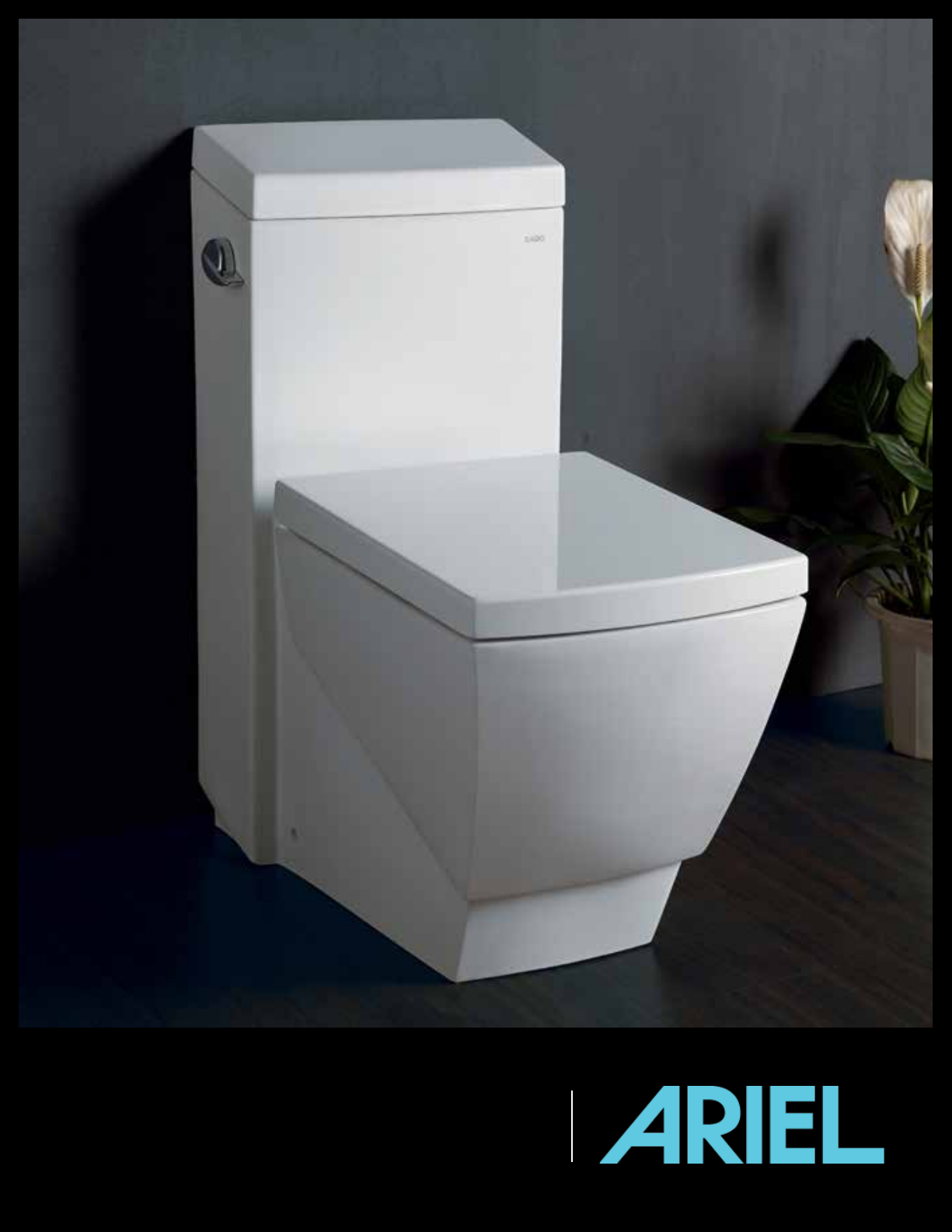
ARIEL PLATINUM TB336M
INSTALLATION GUIDE
Page 2

ARIEL PLATINUM
TOILET MANUAL
INVISIBLE L-MOUNT BRACKETS
TABLE OF CONTENTS
1. Sizing and Details
2. Necessary Tools and Materials
3. Precautions Before Installation
4. Installation
a. Positioning of the Drain Socket Flange
b. Installation of the L-Mount Brackets
c. Installation of the Toilet
d. Installation of the Toilet Seat
5. Recommended Measurements
6. Testing Operation
7. Troubleshooting & Solutions
8. Product Warranty
9. Customer Support & Technical Support
1
2
3
4 - 8
4
6
7
8
9
9
10
11
11
Page 3
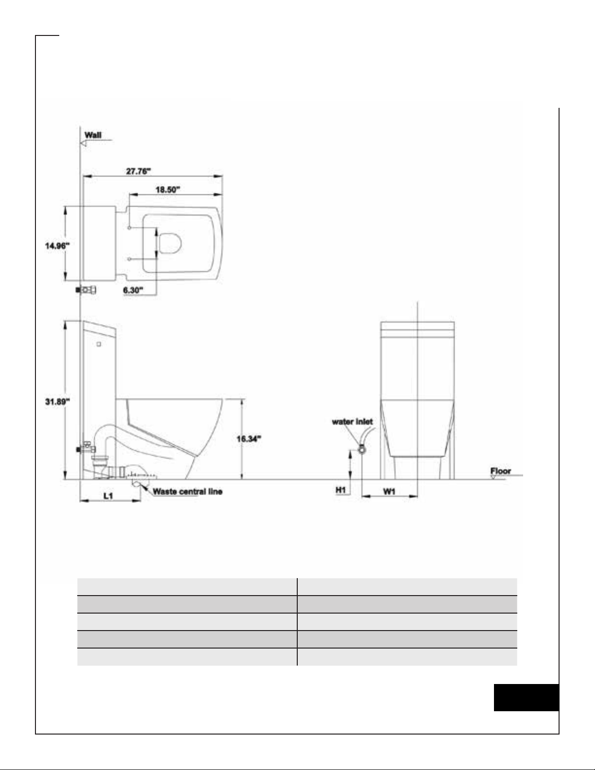
SIZING AND DETAILS
ARIEL PLATINUM TB336M
CONTEMPORARY EUROPEAN TOILET WITH DUAL FLUSH
LENGTH 27.8”
WIDTH 15”
HEIGHT 31.9”
WATER CONSUMPTION 1.6 GPF / 0.8 GPF
TRAP DISTANCE 12”
PAGE 1
Page 4
NECESSARY
TOOLS & MATERIALS
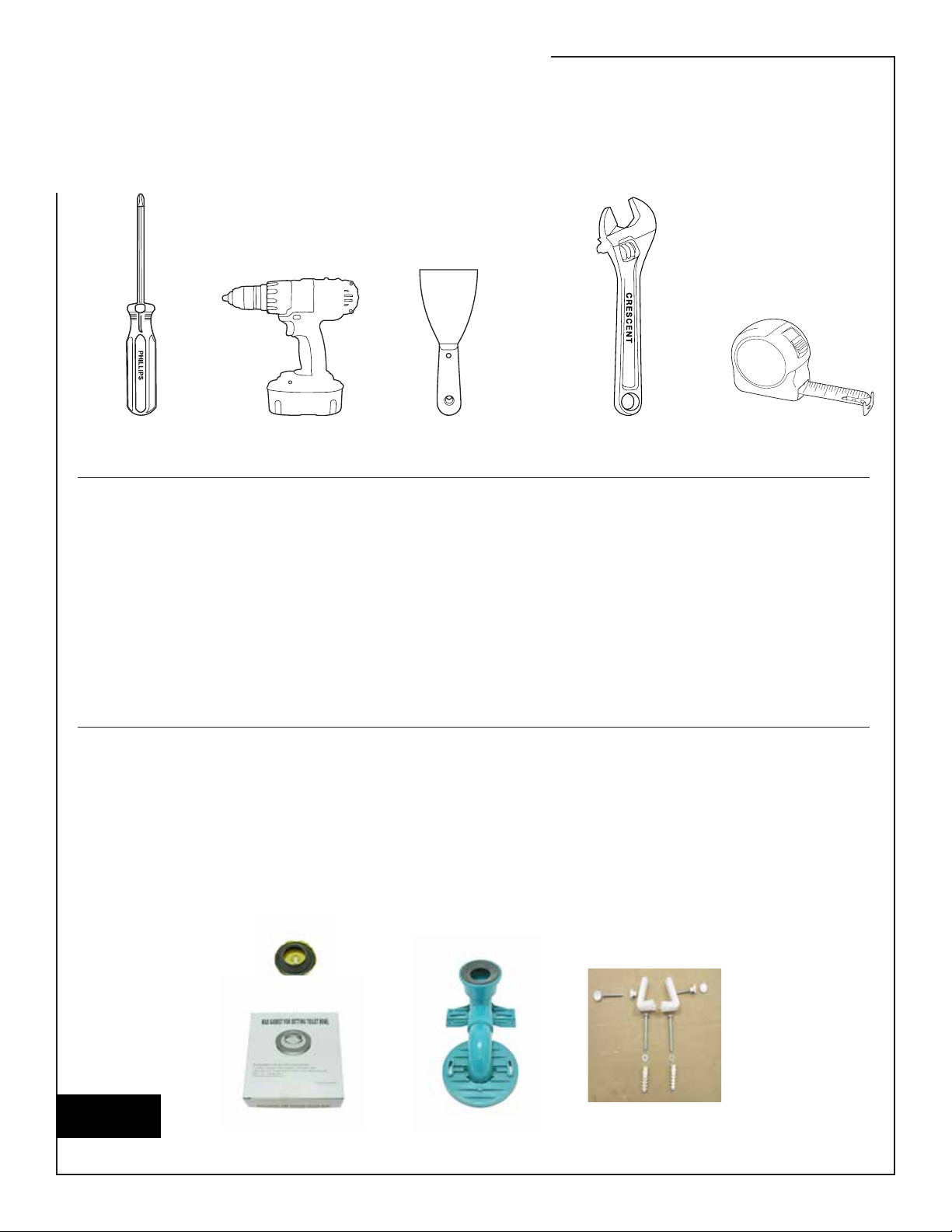
TOOLS
SCREWDRIVER
(Phillips)
PUTTY KNIFE
(Optional)
CRESCENT WRENCHDRILL
NECESSARY MATERIALS
Water Supply Valve
(also known as a water supply stop or water supply tting)
Water Supply Line
Tape
Silicone
(color of your choice)
Closet Flange
(if the existing closet ange is not used in this installation)
INCLUDED MATERIALS
Wax Ring
Seat Hardware Kit
Not pictured
(varies among models)
TAPE MEASURE
PAGE 2
Skirt Mounting Hardware
Drain Socket Flange
WAX RING DRAIN SOCKET
FLANGE
SKIRT MOUNTING
HARDWARE
Page 5

PRECAUTIONS BEFORE
INSTALLATION
Please note, two people are needed
during installation to place the toilet.
NOTE: The toilet ange is referred to
as the drain socket ange, and the oor
ange is referred to as the closet ange
for the purposes of this manual.
Before installing this product, note the
required and recommended water
supply line pressure is between 20
and 80 psi.
Before installing your new toilet, the
rough-in distance needs to be checked.
The distance between the oor drain
and the water supply valve also needs
to be checked. Please reference the
“Recommended Measurements”
section and the measurements for the
model you have purchased.
Oil, lm, dust and other particles may
come in contact with the product during
transportation and shelf life.
ANY and ALL residue must be removed
from the closet ange.
The old closet ange bolts may need to be
replaced.
Cleaning products prevent bacteria
from growing on the surface of this
product. While the cleaning products are
antibacterial, it cannot be ensured that
all bacteria are destroyed.
PAGE 3
Page 6
INSTALLATION
POSITIONING OF THE DRAIN SOCKET FLANGE
1. Remove the old toilet
and the old wax ring
with the putty knife.
2. Clean the closet ange
thoroughly so there is
no leftover residue.
3. Dry t the drain socket
ange (using the existing
bolts in the closet
ange) and position it so
it is straight.
NOTE: Do not install
the new wax
ring in this step.
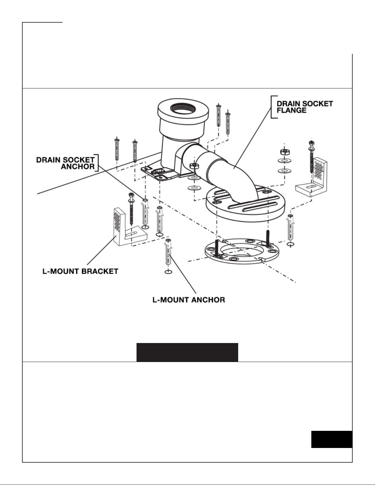
4. Mark the position of the
pilot holes for the drain
socket mounting screws
at the rear of the drain
socket ange. (You will
mark 4 holes in total.)
(See Illustration A)
5. Remove the drain
socket ange and drill
the 4 pilot holes. Insert
the anchors into the
pilot holes.
NOTE: The existing
closet ange
may be used in
this new toilet
installation,
or you may
purchase and
install a new
closet ange.
6. Fit the drain socket over
the closet ange, using
the existing bolts, or
you may purchase new
bolts.
NOTE: The center of
the drain socket
ange must be
aligned with the
center of the
closet ange.
(Clogging may
occur if the
drain socket
is attached off
center.)
7. Secure the drain socket
with the washers and
mounting screws.
8. Dry t the toilet.
9. Use tape to mark the
edge of the toilet skirt
directly below the
mounting holes on each
side of the toilet (these
marks will be used to
measure the placement
of the L-mount
brackets).
10. Also mark the center
edge of the front of
the skirt with tape (this
mark will be used for
placement of the toilet
later in the installation).
11. Remove the toilet.
PAGE 4
Page 7
INSTALLATION
ILLUSTRATION A
PAGE 5
Page 8

INSTALLATION
CONT’D
INSTALLATION OF THE L-MOUNT BRACKETS
1. Measure the thickness of the toilet skirt. It is recommended to add 1/8” to this
measurement. Measure this total measurement (thickness of the toilet skirt plus
an additional 1/8” as recommended) in from the tape marks made in Step 9 of the
previous section. Mark for placement of the L-mount brackets.
2. Dry t the L-mount brackets and mark the pilot hole for each L-mount bracket.
3. Drill the 2 pilot holes and insert the L-mount bracket anchors into the pilot holes.
4. Replace the L-mount brackets and secure them with the screws.
PAGE 6
Page 9
INSTALLATION
CONT’D
INSTALLATION OF THE TOILET
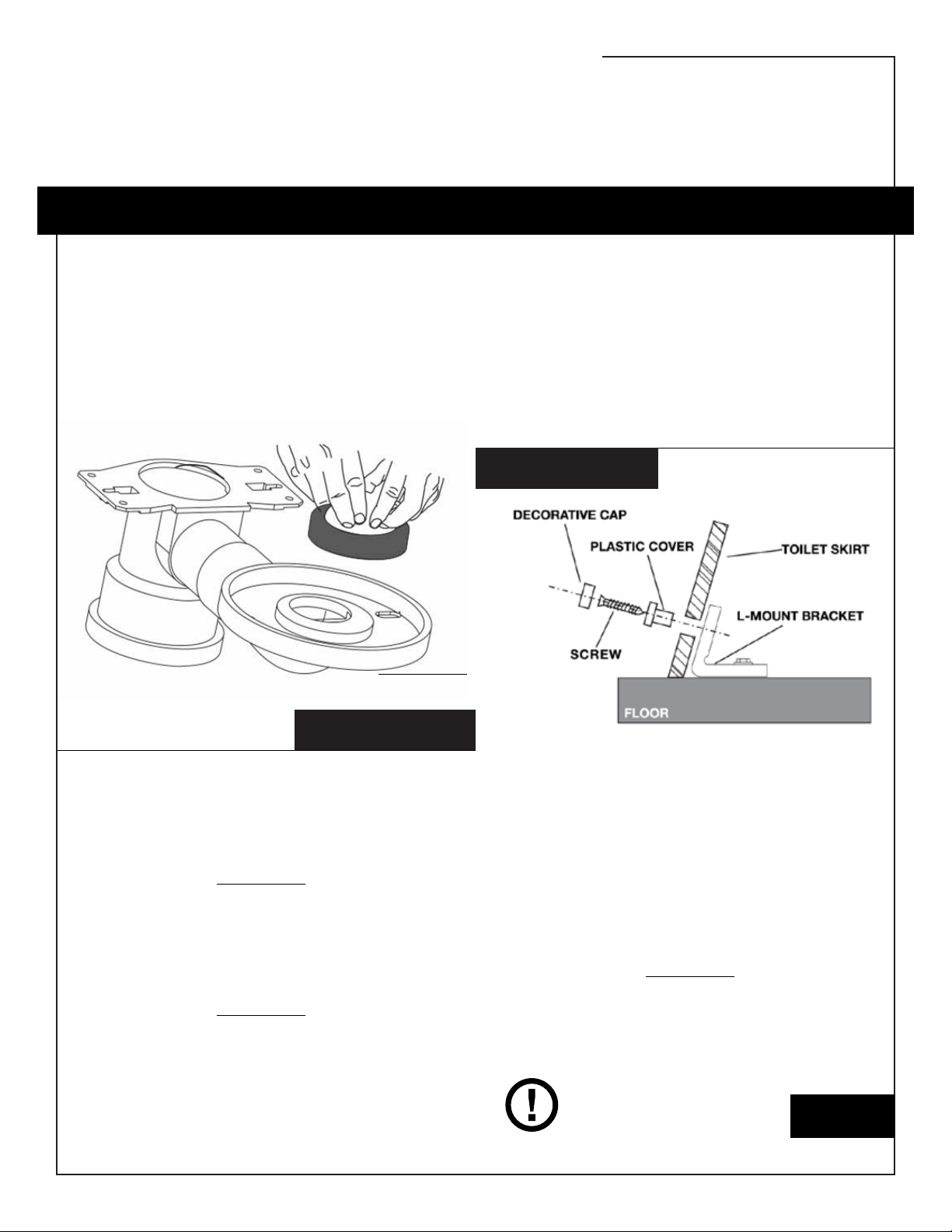
1. Remove the drain socket ange.
Attach the new wax ring to the bottom
of the drain socket ange.
(See Illustration B.)
ILLUSTRATION B
5. Secure the toilet by installing the
screws, plastic cover and decorative
cap into the mounting holes on each
side of the toilet. (These secure the
toilet to the L-mount brackets. See
Illustration C.)
ILLUSTRATION C
2. Reinstall the drain socket ange as
done in Steps 6-7 of “Positioning the
Drain Socket Flange” (on page 4).
3. Attach the water supply line (a
steel braided water supply hose is
recommended) to the tank ller valve
on the toilet.
4. Two people are needed to move the
toilet into place. The tape you placed
earlier shows you where to place the
front of the skirt.
6. Attach the water supply line to the
water supply valve on the wall.
7. Seal the toilet to the oor with silicone
around the bottom edge of the skirt.
NOTE: Do not move the toilet until the
silicone is dry.
PAGE 7
Page 10

INSTALLATION
CONT’D
INSTALLATION OF THE TOILET SEAT
ATTACHING THE TOILET SEAT
METHOD A
(WITH MOUNTING PLATE):
1. Install the mounting plate bolt for the
toilet seat into the mounting hole on
the toilet bowl.
2. Turn the mounting plate bolt for
the toilet seat with a screwdriver
to secure the mounting plate. The
tilted surface should face the front of
the toilet bowl after you attach the
mounting plate for the toilet seat.
METHOD B
(WITH BOLTS):
1. Place the new toilet seat on the toilet
bowl with the hinges over the bolt
holes in the toilet bowl.
METHOD C (STANDARD)
5. With the hinged section of the toilet
seat, set the toilet seat on the mounting
plate for the toilet seat.
6. The securing screw for the toilet seat
is used on the side of the toilet seat.
(Without the securing screw, the toilet
seat will be loose.) Insert the securing
screw for the toilet seat into the
mounting hole on the side of the toilet
seat.
2. Open the hinge caps if applicable.
3. Drop the bolt through the open hinge
and bolt hole.
4. Screw the bolt until snug.
PAGE 8
Page 11

RECOMMENDED
MEASUREMENTS
1. The recommended rough-in distance between the center of the closet ange and
the wall is 12”.
2. The recommended distance between the center of the closet ange and the water
supply valve on the wall is 9” to 11”, depending upon the toilet model.
3. The recommended distance between the water supply valve and the oor is 11.5”.
TESTING OPERATION
1. Check the water level in the tank. The water level should reach the waterline
for the overow pipe when the tank is full. If not, you will have to use the
following guidelines for adjusting the water level.
2. Flush the toilet and check for leaks between connecting sections while the toilet is
ushing.
PAGE 9
Page 12

TROUBLESHOOTING
& SOLUTIONS
Problem 1: The toilet is not ushing. Solutions:
Problem 2: The toilet leaks. Possible Causes:
Problem 3: The toilet ush is weak. Possible Causes:
Possible Causes:
1. The supply line is blocked.
2. The ush button pushrods are
not contacting the ush valve.
3. The water supply valve is closed.
1. The drain socket ange is loose.
2. The water supply hose is not
connected correctly.
1. The supply valve is partially
closed.
2. There is clogging in the strainer.
3. The water level in the toilet bowl
is too low.
4. The trapway and/or the vent
and/or the drain pipe are
partially clogged.
1. You will need to turn off the
water supply and disconnect
the supply line. Also, inspect all
of the washers.
2. The length of the ush button
pushrod needs to be adjusted
as needed.
3. Open the water supply valve by
lifting the tank ller oat and let
the toilet tank ll.
Solutions:
1. Make sure that the bowl and
oor connection are connected
properly, and make sure the
toilet bowl is secured correctly.
2. Disconnect and reconnect the
water supply hose. Plumbers
tape may be needed.
Solutions:
1. Fully open the supply valve.
Ensure that the water supply
line size is the correct size.
2. The strainer, inside the valve
shank, needs to be cleaned
(even if it is new).
3. Make sure the rell tube is
connected with the overow
tube.
4. You need to eliminate the
obstruction. You may need the
assistance of a professional
plumber.
Problem 4: The toilet will not shut
off.
PAGE 10
Possible Causes:
1. The apper and/or the ush
valve are deformed or worn out.
2. The pushrods holding the ush
valve open are too long.
Solutions:
1. Turn off the water supply. Now,
replace the ush valve gasket.
2. Adjust the length of the
pushrod as much as needed.
Page 13

PRODUCT WARRANTY
The product warranty is a 1 year limited parts warranty from the date it was purchased. There is a warranty statement that accompanies the product. Read the
warranty statement for further information on your warranty.
CUSTOMER &
TECHNICAL SUPPORT
For more information and for customer support, contact Atlas International or our
Technical Support Center at 800-304-3598 during our business hours (Monday
through Friday from 8 am PST to 5 pm PST).
PAGE 11
Page 14

500 West Warner Ave, Ste. A Santa Ana, CA 92707
arielbath.com | atlasusa.net
Email: [email protected] | Phone: 1-714-622-1565
 Loading...