

Page 1
長新科技股份有限公司
ARICO Technology Co., Ltd.
R e g i s t e r e d t o
I SO 9001
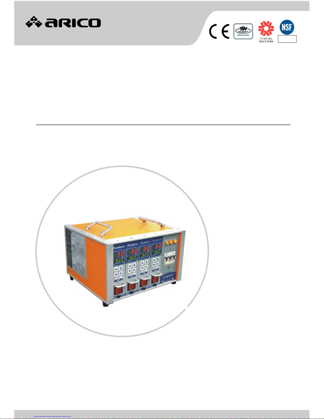
TC5E 熱澆道溫度控制器
TC5E Hot-Runner Temperature Controller
操作手冊
USER'S MANUAL
Ver.:TC5E-1. 0.3
VNA0000008
長新科技股份有限公司
ARICO Technology Co., Ltd.
保有權利於任何時間未經通知而修改或變更本手冊內容及型式,未經本公司同意,不得作任何形式的使用。
reserves the right to make any kind of design or functional modification at any moment without prior notice.
Page 2
ARICO Technology Co., Ltd.
-1-
For
avoid wrong operation to make human injured or machine damage,
pleas
e read this instruction carefully before use the instrument.
CONTENT
Chapter 1 TC5E TEMPERATURE CONTROL
MODULE
1-1 Features 2
1-2 Specification 2
1-3 Faceplate 3
1-4 Operating description 5
Chapter 2 CABINET & ACCESSORIES
2-1 Dimension 9
2-2 Specification 10
2-3 Connection description 10
2-4 Type of power wiring 11
2-5 Connector wiring 13
Chapter 3 ORDER CODERING
3-1 Cabinet 16
3-2 Cable 16
3-3 Housing 17
3-4 Hood 17
3-5 Blank Plate 17
3-6 Connector 17
3-7 Trouble shooting 18
Page 3

-2-
Chapter 1 TC5E TEMPERATURE
CONTROL MODULE
1-1 Features
■ Dual SV temperature control
■ Dual lines LED display
■ Unit display
■ Auto/Manual function
■ PID auto temperature control
■ Selectable two thermocouple types (J or K)
■ Selectable two temperature scales (°C or °F)
■ Selectable six alarm modes
■ Selectable two trigger output modes (Zero cross or phase angle)
■ Fuse break indicator
■ Power frequency auto-detect
■ Thermocouple break and inverse detect
■ Th er mocou pl e ra nge K TY P E :0~ 60 0 °C(32 ~9 99 °F) / J T Y P E : 0 ~ 60 0 °C(32~ 9 99°F)
1-2 Specification
■ Power input: 230VAC±15%
■ Power frequency: 50 / 60Hz
■ Power consumption: 7W (each module)
■ Input impedance: 10MΩ
■ Output wattage: 3600W, 15A / 240VAC
■ Storage temperature: -20~70°C
■ Work temperature: 0~50°C
■ Work humidity: 10~80%RH. (non-condensing)
■ Control accuracy: ±0.25%FS
■ Measure accuracy: ±0.25%FS
Page 4
ARICO Technology Co., Ltd.
-3-
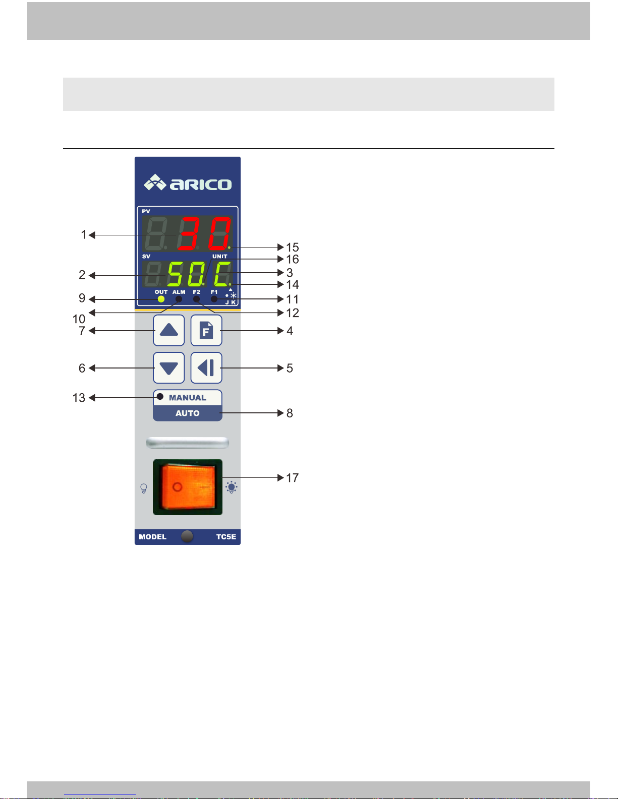
1-3 Faceplate
1-3-1 Faceplate description
(1)PV:
○
1
Normal mode: Present value
○
2
Parameter mode: Parameter
name
(2)SV:
○
1
Normal mode: Setting value
○
2
Parameter mode: Parameter
value
○
3
Manual output mode: Manual
output %
(3)UNIT: Temperature or parameter unit
(4)Function key: Parameter level and
parameter select key
(5)Set k ey: Set e nab le and di gi t al sh ift ke y
(6)Decrement key: Setting number
decrease
(7)Increment key: Setting number
increase
(8)Auto/Manual mode key
(9)Output indicator: Light up when
instrument output
(10)Alarm indicator: Light up when
alarm happen
(11)Fuse 1 indicator: Light up when fuse
1 break
(12)Fuse 2 indicator: Light up when fuse
2 break
(13)Manual mode indicator: Light up
when instrument is in manual mode
(14)Sensor input indicator: Light up
when K type was selected
(15)PID tuning indicator: In PID tuning
progress indicator flash
(16)SV2 indicator: Execute SV2
temperature control indicator flash
(17)Power switch
Page 5
-4-
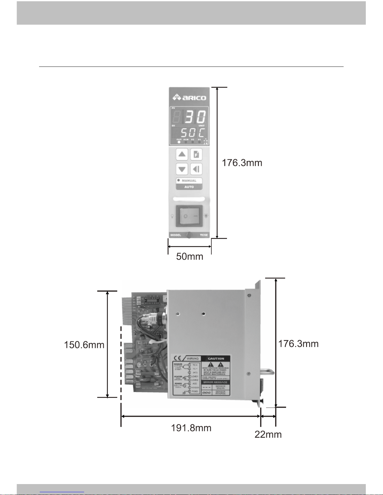
1-3-2 Faceplate appearance and dimension
Deviation: ±5mm
Page 6
ARICO Technology Co., Ltd.
-5-
1-4 Operating description
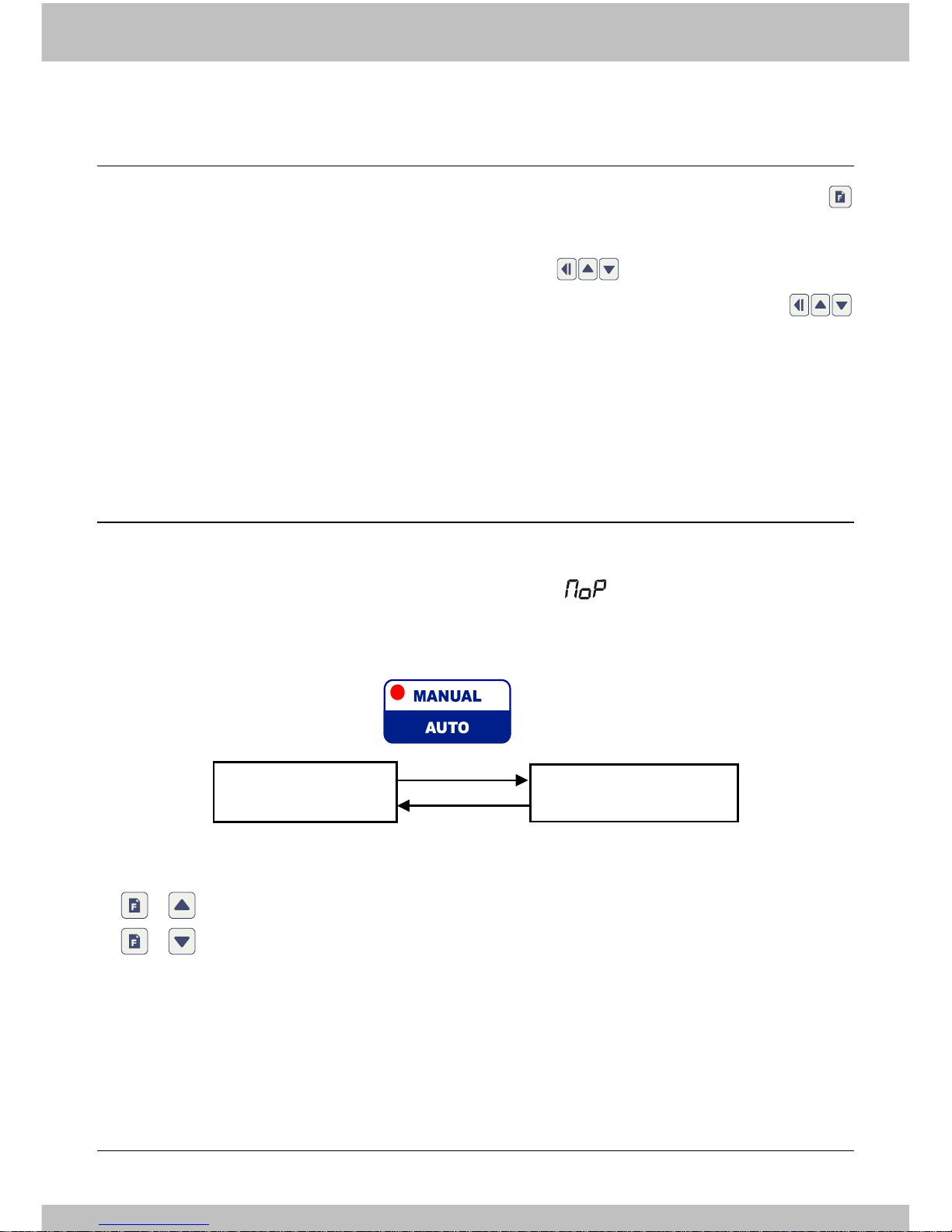
1-4-1 Parameter flow chart
Page 7
-6-
1-4-2 Operating modes
TC5E divide into Main mode and parameter mode. In main mode, press
could entry parameter mode.
Main mode: Controller display PV and SV, use for SV modification.
Parameter mode: Controller display parameter name and its value, use
for value modification.
1-4-3 Control modes
Auto mode: The instrument make auto temperature control.
Manual mode: The instrument follow parameter and make output.
(UNIT field display "P")
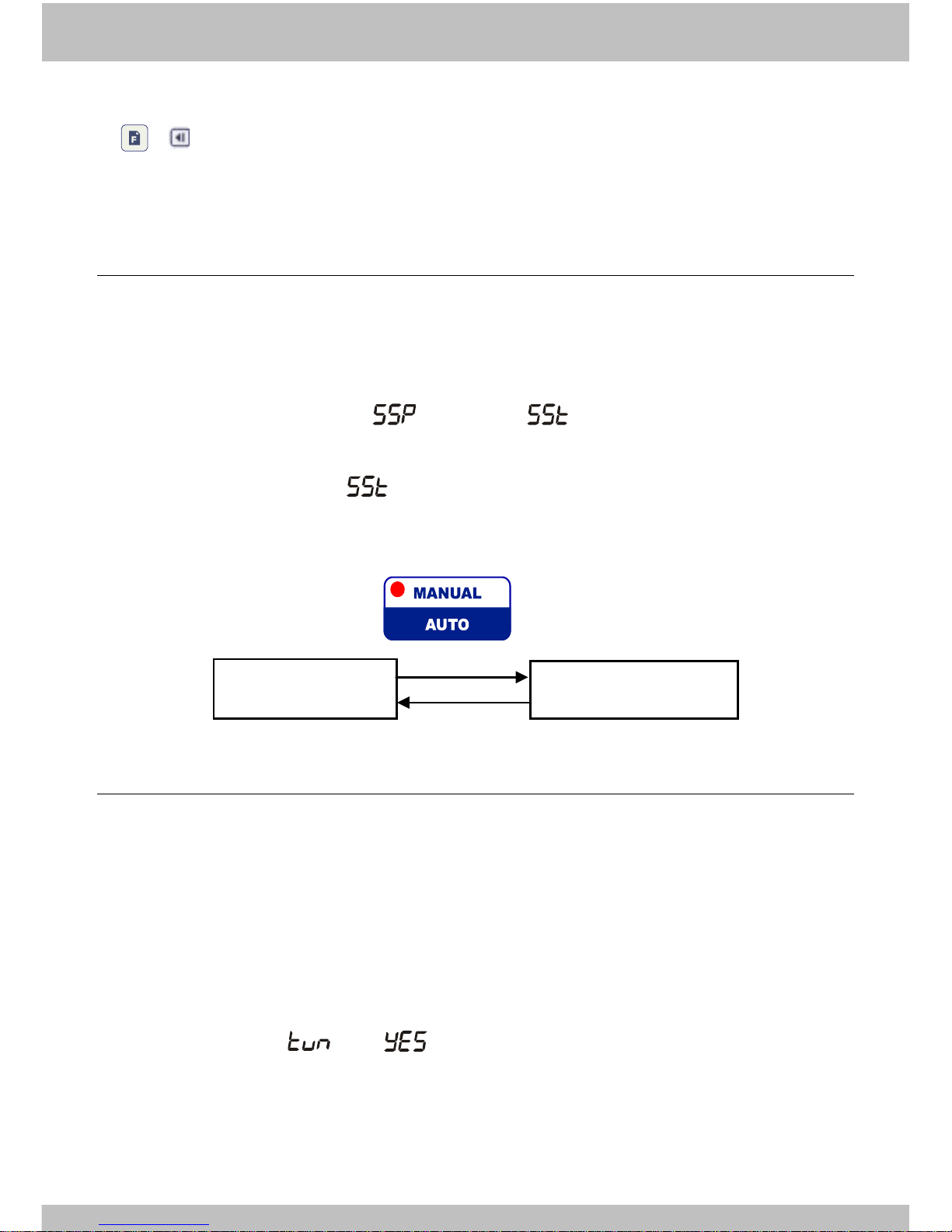
Manual/Auto mode change
+ 2 sec
Exchange SV1 and SV2
+ +3 sec: SV1 temperature control.
+ +3 sec: SV2 temperature control.
※Execute SV2 temperature control indicator flash.
(Refer 1-3-1 faceplate description)
1-4-4 The alarm output function disable temporarily
Auto mode
Manual mode
Page 8
ARICO Technology Co., Ltd.
-7-
+ +1 sec: The alarm output function disable or enable select (when
power re-setting, the default setting is enable)
1-4-5 Soft start (Heater dehumidify) function
To avoid the humidity make the heater burn out. The soft start function could
output a lower current to make dehumidify action when turn on the power.
Soft start condition:
The soft start percentage ( ) and time ( ). After power turn on, if SV >
PV ; PV < 120°C,manual and PID tuning function are disable, the soft start
would be executed. Set to zero for disable soft start function.
Soft start interrupt:
+ 1 sec
1-4-6 PID auto tuning function
For get the optimal PID value in some system, it is possible to execute "PID
auto tuning" function when first use or heater system changed.
After finished auto tuning, the optimal PID would be save into the instrument
Start PID auto tuning function:
(1)PV must lowerthan120°C or 180°F
(2)SV must higher than PV for 80°C or 100°F
(3)Set parameter into
PS:During PID auto tuning execution, the decimal point of PV would flash.
After instrument get the optimal PID, the decimal point turn off and
instrument recovery to auto temperature control.
Soft start
Manual/Auto mode
Page 9
-8-
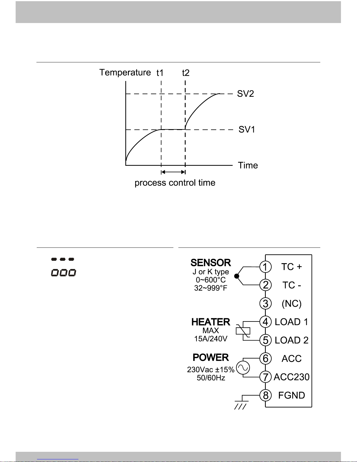
1-4-7 Process control
1-4-8 Error message
(1) :Input break
(2) :Input reverse
1-4-9 Wiring
Page 10
ARICO Technology Co., Ltd.
-9-
Chapter 2 CABINET
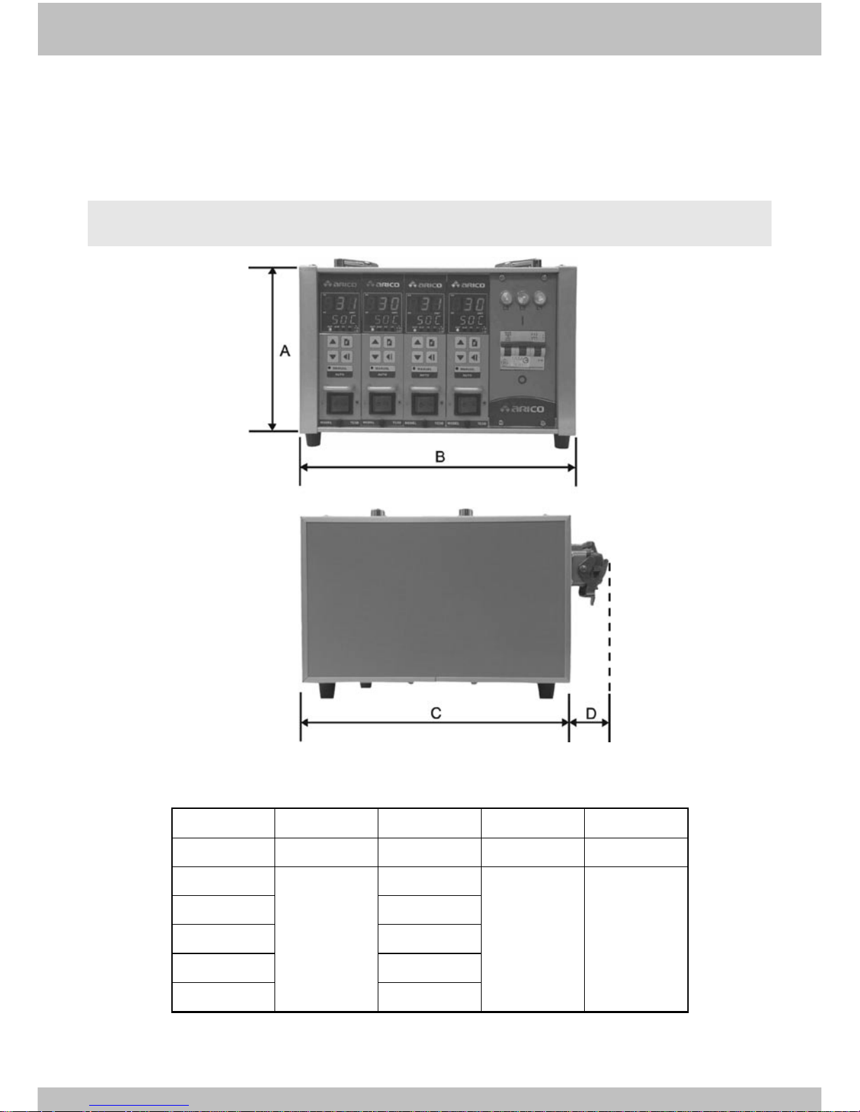
2-1 Dimension
Unit: mm
Cabinet
A B C
D
1 Zones
188
96
248
30
2 Zones
215
223
299
45
4 Zones
323
6 Zones
424
8 Zones
524
12 Zones
726
Page 11
-10-
2-2 Specification
Type
T5A01
T5A02
T5A04
T5A06
T5A08
T5A12
Zone
Item
1 2 4 6 8
12
Power Switch
capacity(A)
--
32
50
50
63
63
Output
Connector
4pin+E
(ground)
16pins
x1
16pins
x1
24pins
x1
16pins
x2
24pins
x2
Power Cable
2.0mm2
x3C
x3M
5.5mm2
x5C
x3M
5.5mm2
x5C
x3M
5.5mm2
x5C
x3M
8.0mm2
x5C
x3M
8.0mm2
x5C
x3M
Weight(kg)
(non-module)
1.75
7.25
9
11.25
12.5
16
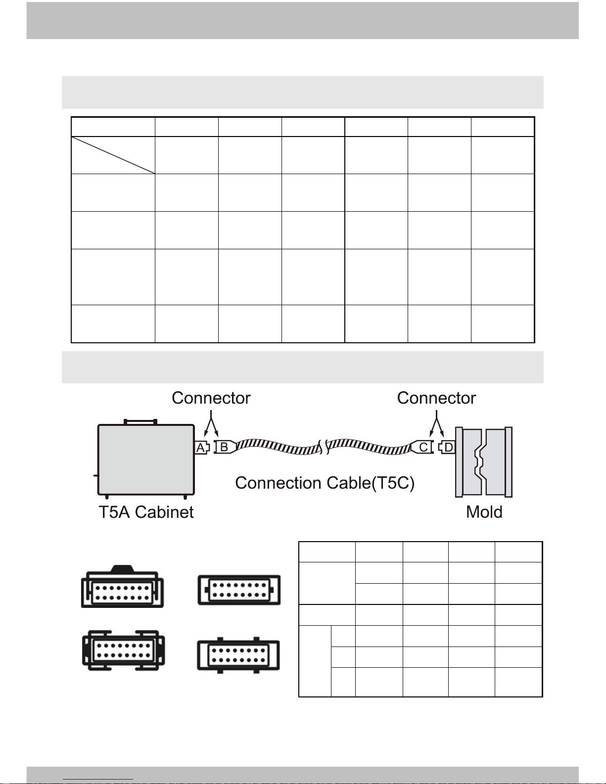
2-3 Connection description
Connector type
a: single hook b: single button
c: dual hook d: dual button
Connector
A B C
D
Name
Housing
Hood
Hood
Housing
T5E
T5F
T5F
T5E
Type
Socket
Plug
Socket
Plug
C o m b i n a t i o n
1* a b b A
2 c d d C
3 d c c d
*Standard type
**T5A01 only for type 1
Page 12
ARICO Technology Co., Ltd.
-1 1 -
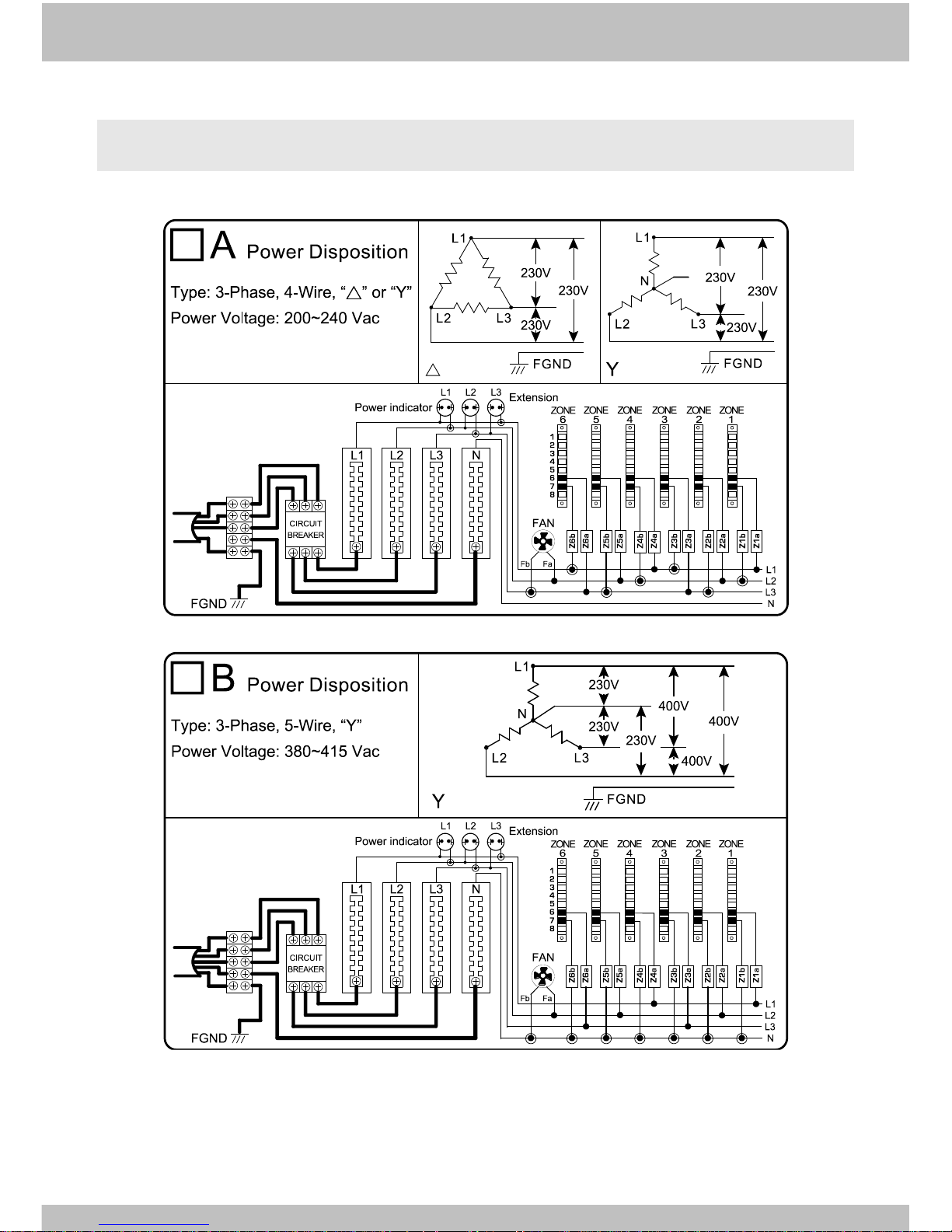
2-4 Type of power wiring
Page 13
-12-
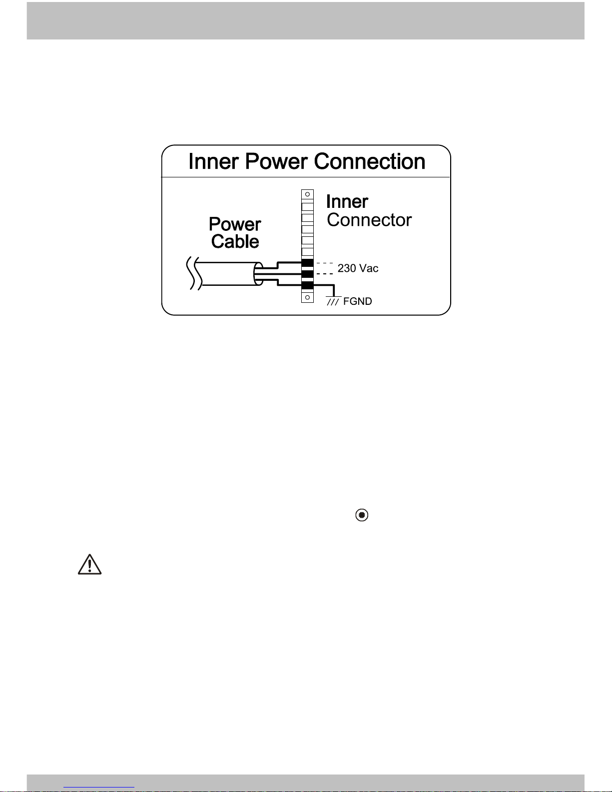
The following power wiring only for T5A01
Caution
1. Before operating, check connection ("y" or "△")and its voltage.
2. All instruments must be used in accordance with the specification to prevent
fire or damage to instrument and equipment.
3. Be sure the ac power input is switched off before maintenance.
Note: power type A and B differ with regard to " " connections.
The FGND must be connected with earth ground.
Page 14
ARICO Technology Co., Ltd.
-13-
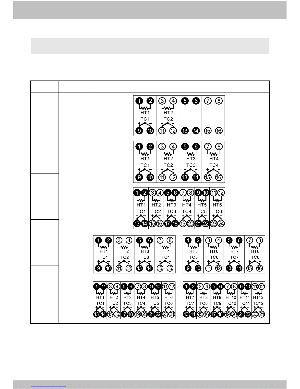
2-5 Connector wiring
Cabinet connector wiring are divided into A, B and C type as below:
A type wiring
ZONE
CONN.
CONNECTOR ASSIGNMENT
2
16*1
A16-2
4
16*1
A16-4
6
24*1
A24-6
8
16*2
A16-8
12
24*2
A24-12
Page 15
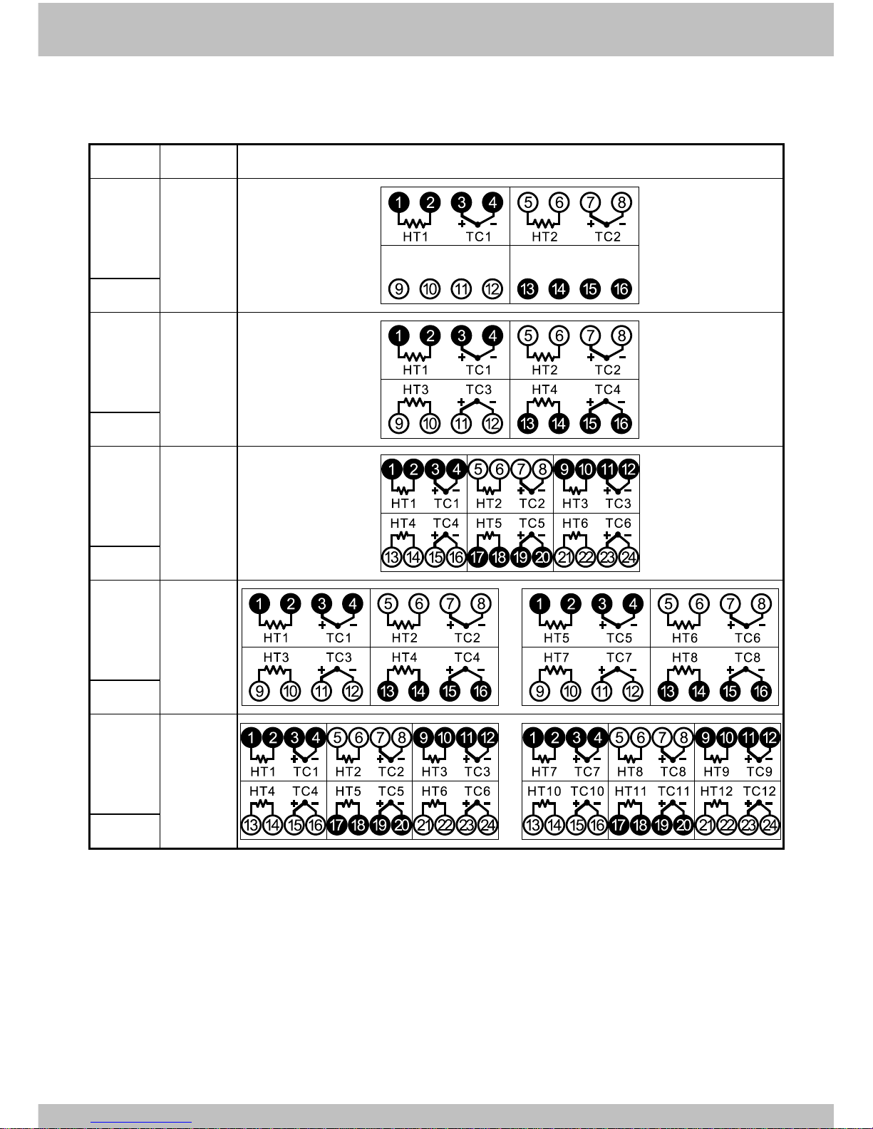
-14-
B type wiring
ZONE
CONN.
CONNECTOR ASSIGNMENT
2
16*1
B16-2
4
16*1
B16-4
6
24*1
B24-6
8
16*2
B16-8
12
24*2
B24-12
Page 16
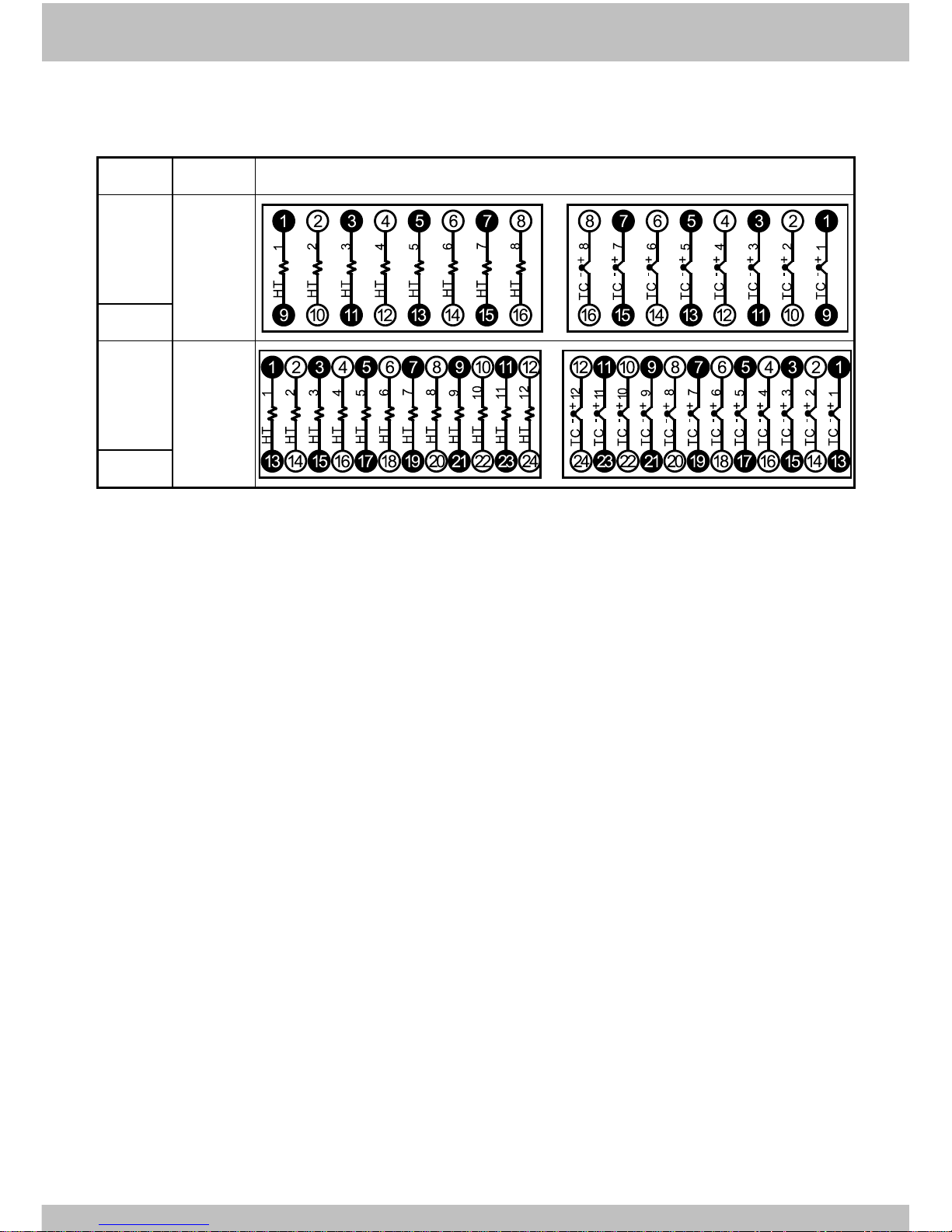
ARICO Technology Co., Ltd.
-15-
C type wiring
ZONE
CONN.
CONNECTOR ASSIGNMENT
8
16*2
C16-8
12
24*2
C24-12
Page 17
-16-
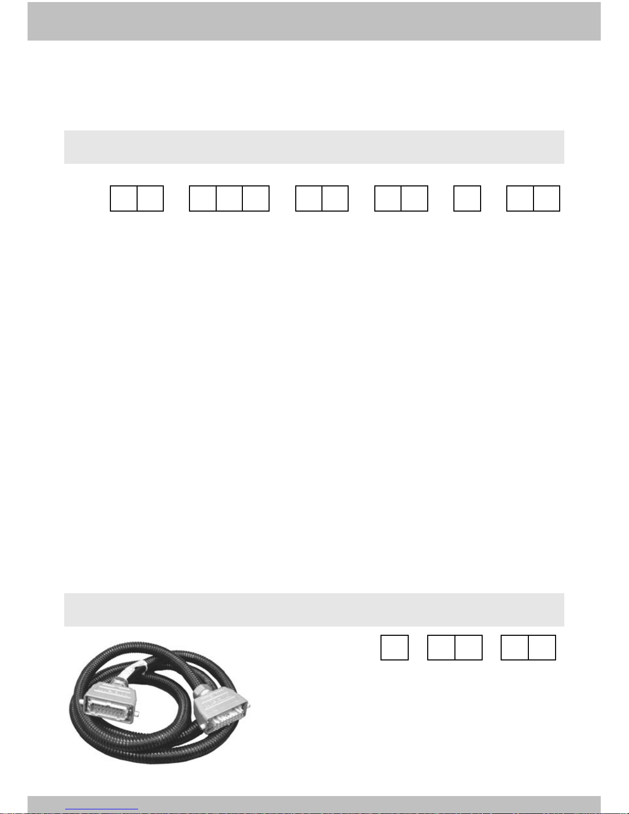
Chapter 3 ORDER CODE
3-1 Cabinet: T5A
T5A
- - - - -
a b c d e
f
a:Zone
01:1 zone
02:2 zones
04:4 zones
06:6 zones
08:8 zones
12:12 zones
b:Housing and Hood
SHB:Housing is single hook, hood is single button*
DHB:Housing is dual hook, hood is dual button
DBH:Housing is dual button, hood is dual hook
c:Power Wiring
A0:A type 3-phase 4-wire 200~242VAC
B0:B type 3-phase5-wire 380~415VAC
A1:A type 3-phase 4-wire 200~242VAC*
B1:B type 3-phase5-wire 380~415VAC*
*:For 1 zone T5A01
3-2 Cable: T5C
Order code:
T5C
- -
a b
c
a: Wiring
b: Pins--4, 16, 24
c: Length(M)
◎Standard Length 3M
d:Power Cable Length
03:3m (standard)
e:O/P Connector Wiring
A:A t y p e
B:B type
C:C type
f:Cable Wiring
00:Without connection cable
03:3m (standard)
Page 18
ARICO Technology Co., Ltd.
-17-
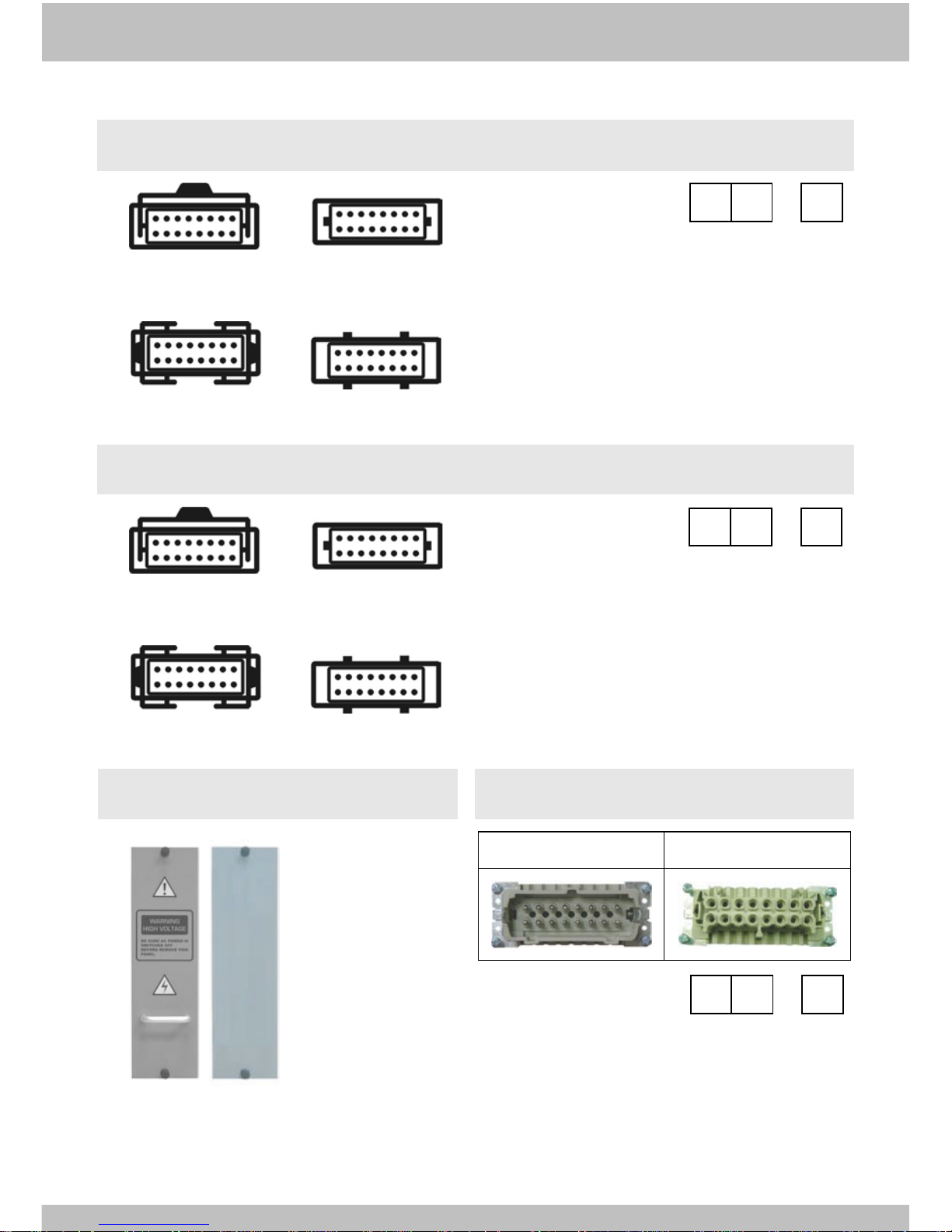
3-3 Housing: T5E
Single hook Single button
Dual hook Dual button
a: Pins--4, 16, 24
b: Type
1:Single hook
2:Dual hook
3:Single button
4:Dual button
Order code:
T5E
-
a
b
3-4 Hood: T5F
Single hook Single button
Dual hook Dual button
a: Pins--4, 16, 24
b: Type
1:Single hook
2:Dual hook
3:Single button
4:Dual button
Order code:
T5F
-
a
b
3-5 Blank plate:T5G
Order code:T5G
3-6 Connector:T5D
1. Plug
2. Socket
a: Pins--4, 16, 24
b: Type
1:Plug
2:Socket
Order code:
T5D
-
a
b
Page 19
-18-
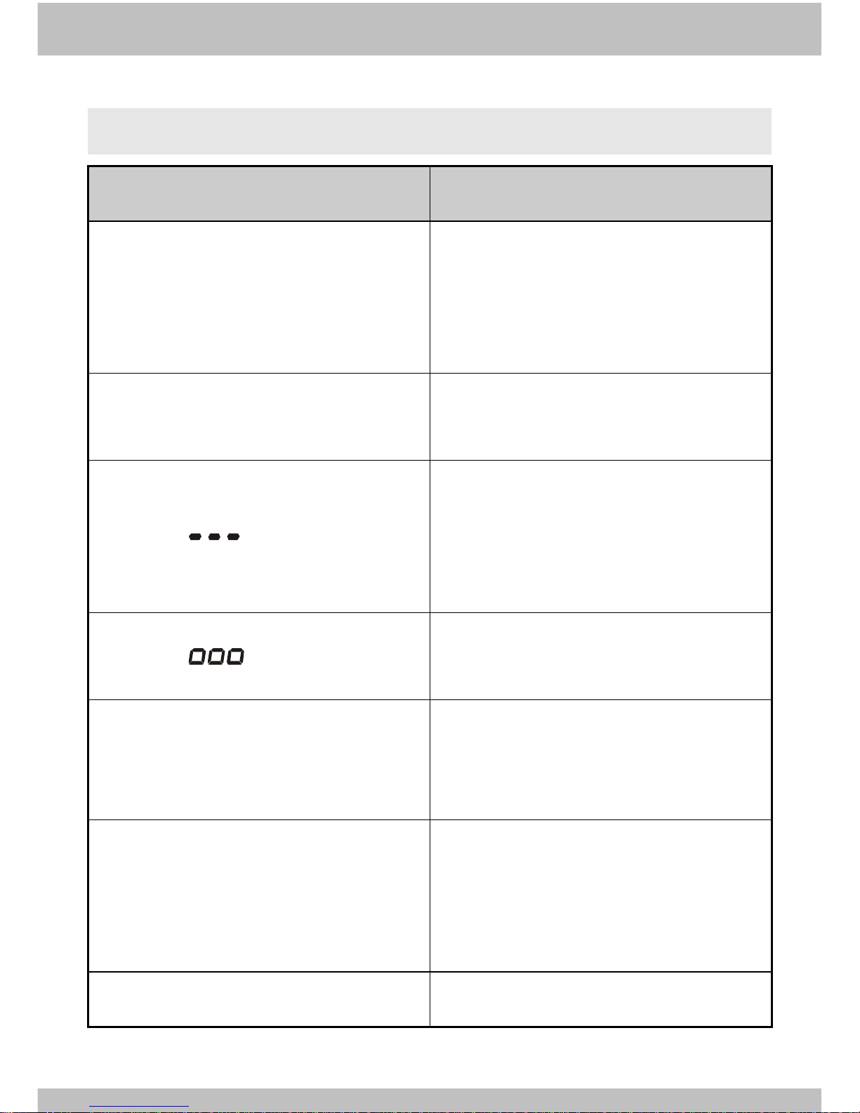
3-7 Trouble shooting
Malfunction status
Check item
1.No action after power on.
TC5E is installed properly?
Power wiring is correct?
Main power switch is malfunction?
TC5E module is malfunction?
2.F1 or F2 fuse break indicator bright.
Change th e fuse ac cord wi th th e br igh tly
in dicator.
3.Display " "
TC5E is installed properly?
Thermocouple is break?
Extension cable is loose or breaks?
TC5E module is malfunction?
4.Display " "
Thermocouple is reverse?
TC5E module is malfunction?
5.No display PV normally or PV unstable.
Refer item 3.
Power leakage?
The ground is properly?
6.I n th e nor mal op er at ion, th e tempera tu re
ca nnot rise u p.
TC5E is installed properly?
Extension cable is loose or breaks?
Heater is malfunction?
TC5E(TRIAC) is malfunction?
7.Temperature control is unstable.
Refer 1-4-5, execute PID self-tuning.
Page 20
ARICO Technology Co., Ltd.
-19-
長新科技股份有限公司
ARICO Technology Co., Ltd.
總公司
(HEADQUARTERS)
23145
新北市新店區寶橋路
235巷1弄1號8樓
8 F . , N o . 1 , A l l e y . 1 , L a n e 2 3 5 , B a o c i a o R d . , Sindian District, New Taipei City, 23145, T a i w a n
TEL:+886-2-29101266
FAX:+886-2-29159434
www.arico.tw / www.arico.com.tw
 Loading...