

Before you proceed with the installation, please notice the following
descriptions.
Note 1: The following installation was operated under Windows XP.
(Procedures are similar to Windows 98SE/Me/2000.)
Note 2: If you have installed the WLAN USB driver & utility already, please
uninstall the old version first.
Note 3: Do not insert the wireless LAN adapter into your computer until
the procedure of “
Install the Driver & Utility"
has been performed.
1. Installation
1.
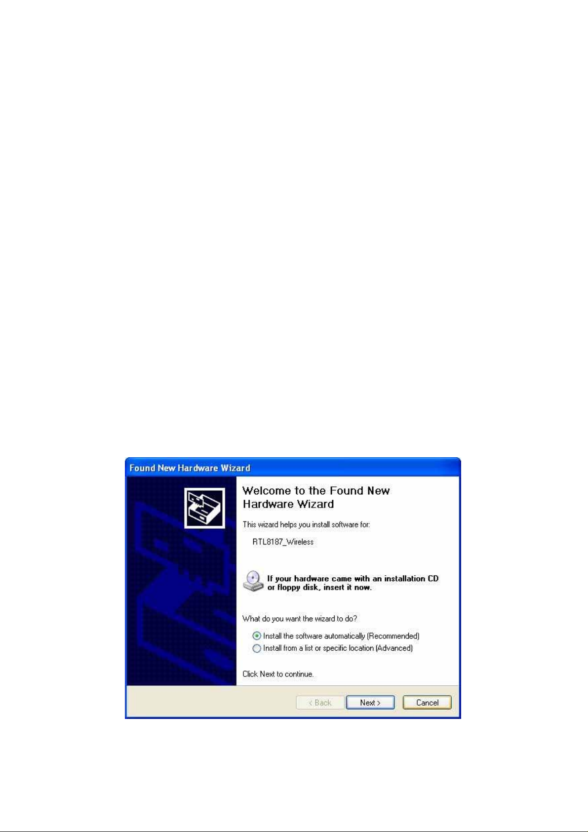
If you insert the Wireless LAN USB Adaptor into your computer USB port
``installing the softwar e program from the CD, then the following window
after
up.
pops
2.
Click Cancel.
3.
Choose a set up language.
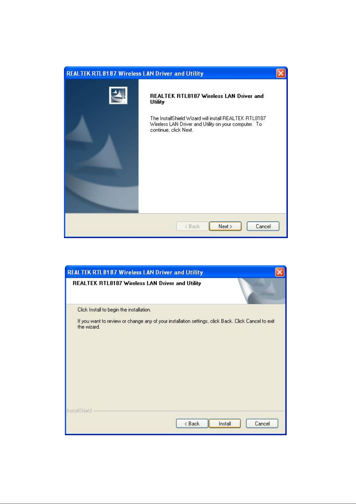
4.
Click Next to process the installation. .
5.
Click Install to WLAN USB adaptor installation.
6.
On Windows Logo Software Installation screen, click Continue Anyway to
continue.
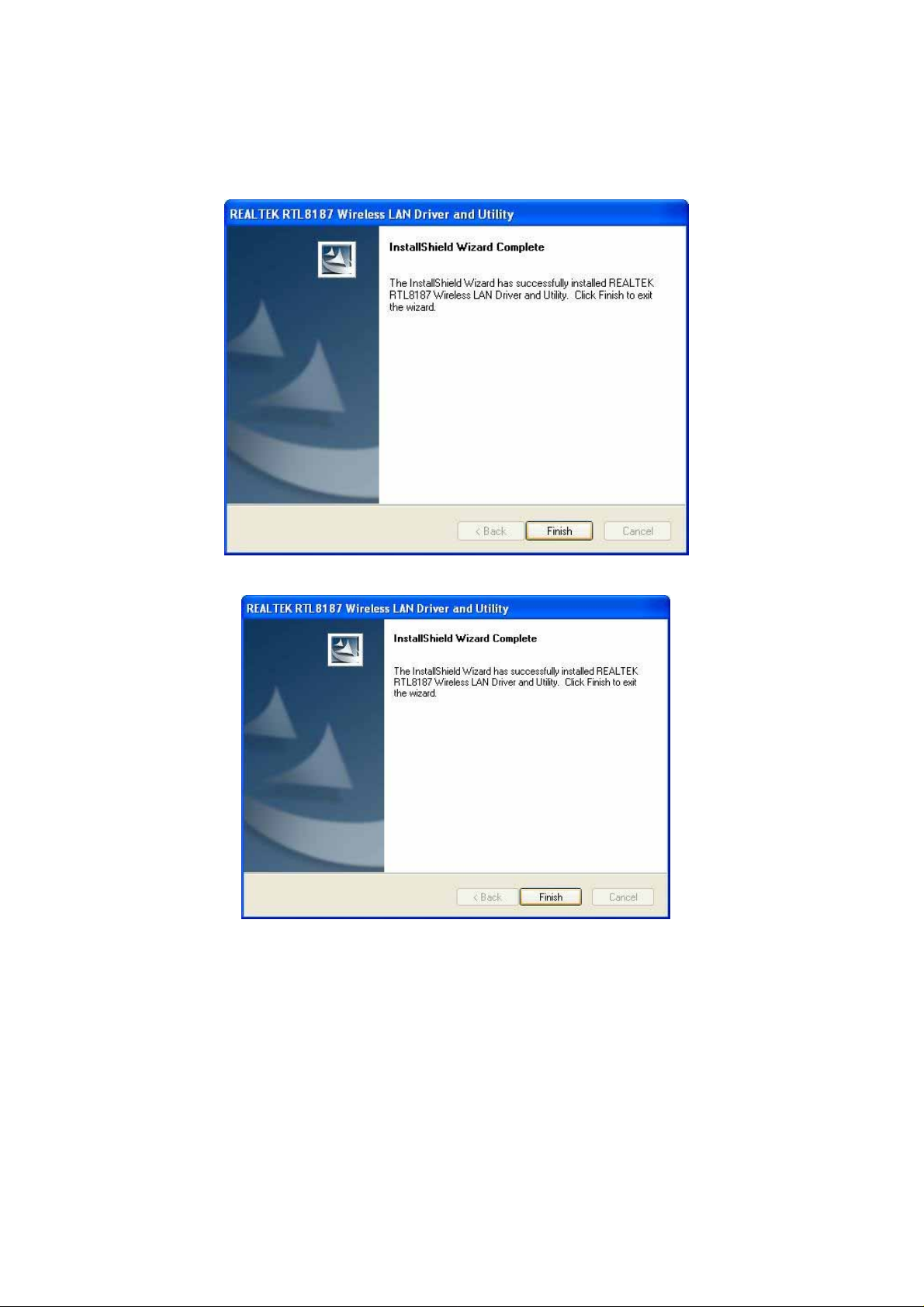
7.
Click Finish to complete the installation.
8.
After setup, restart your computer
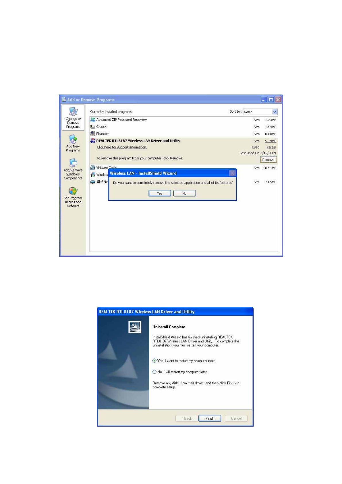
2. Uninstallation
A. Uninstall the WLAN USB Adaptor Driver from “
Utility" or “Control
“
Change/Remove") to remove Wireless LAN USB Adaptor driver.
Panel".
Wireless Network Driver and
Click “
Uninstall"
(or
B. Click “OK" if you want to remove Wireless LAN USB Adaptor
Driver.
C. Click “
Finish" to
complete the uninstallation.

Making a Basic Network Connection
In the following instruction for making a network connection, we u
se the utility w
e
provided to configure your wirel
Note: For Windows XP users that want to configure your wireless network using this
Utility, pl
wirel
ease perform the following procedur
ess support (Wireless Zero Configuration
ess network settings.
es to disable your nativ
Service)
e Window
s X
1. Doubl
the task bar.
e click th
e icon on your desktop to start the ut
ility or in
P
Ad-Hoc Mode
A
n Ad-Hoc mode wirel
a
router or AP.
install this wireless adapter to two computers respectively. Th
communication
ess network connects two computers directly without the u
It is also
known
as a peer-to-peer network. For example, we ca
e
se of
n
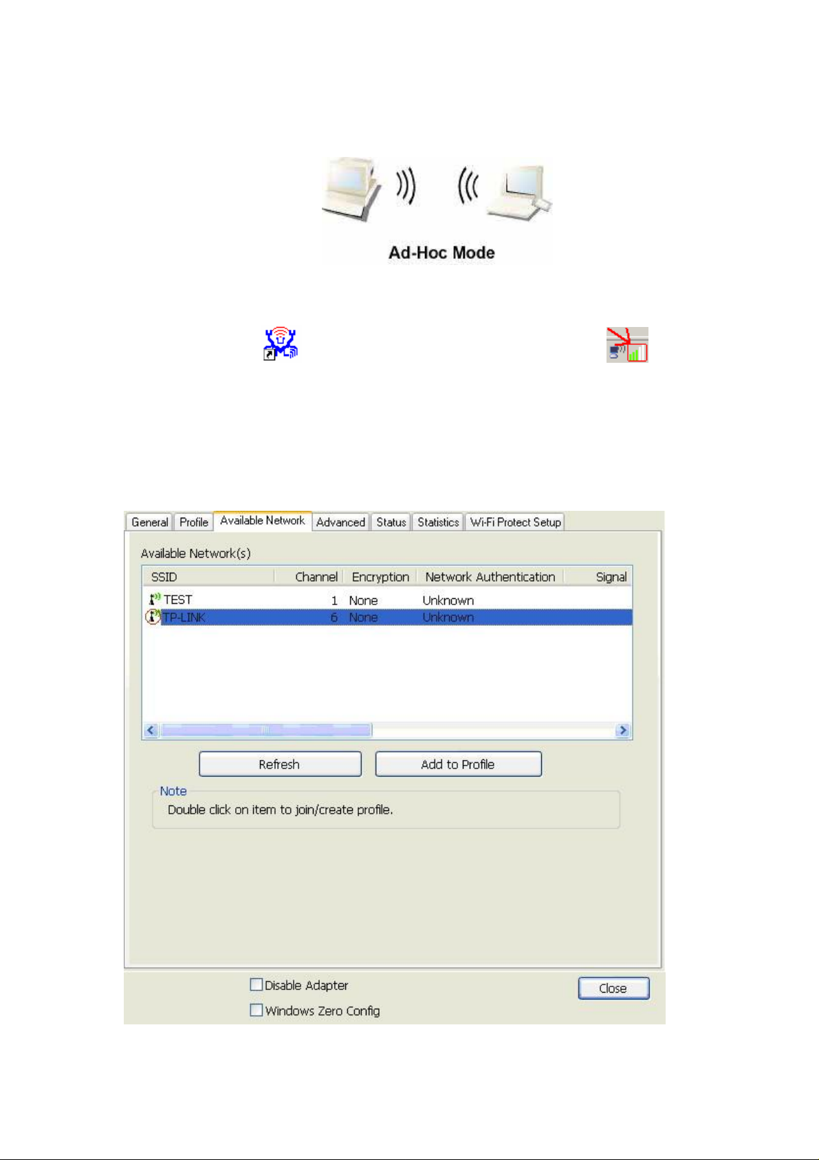
between the two computers i
s an Ad-Hoc mode network.
To use this adapter in Ad-Hoc Mode
1. Doubl
the task bar.
e click th
e icon on your desktop to start the ut
2. Click the
network adapters. Doubl
connect to.
“Available Network" button to scan available wirel
e click on the network adapter that you are going to
ility or in
ess
3. Click the OK button to confirm that you ar
network.
e connecting to an open wirel
ess
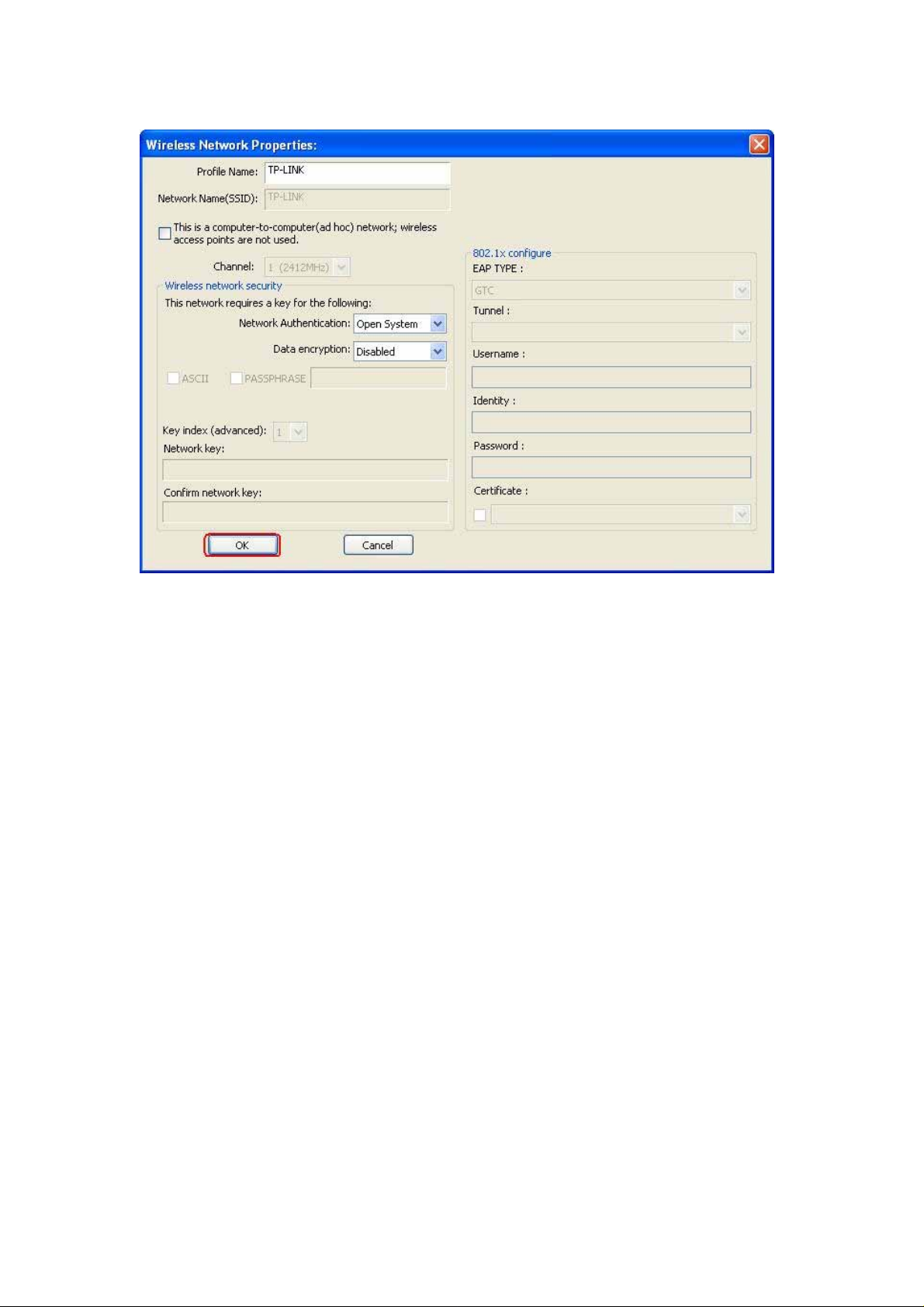
4. Click OK to add this network into the profile list.
Note: Thi
W
ireless adapter with security protection, you w
s example is an open wireless network. If you are going to connect to a
ill have to configure th
e encryptio
n
settings in this profile to b
the
“Network Authentication" drop list to
a
nd then select a
“OK".
“Data encryption" type. Fill in each required blank
e corresponding to the other wireless adapter. Pl
ease click
select an authentication method,
s and click
o

Infrastructure mode
An Infrastructure Mode network
and one
wirel
ess AP or router. Thi
s client connects to Internet or intranet by co
contain
s at least one wirel
mmunicating
ess client
with this wireless AP.

To use this adapter in Infrastructure Mode:
1. Doubl
e click th
e icon on your desktop to start the ut
ility or in
the task bar.
2. Click the
D
ouble click on the AP that you are going to connect to.
“Available Network" button to
scan availabl
e access points.
3. Doubl
network.
e click to create profile that you are connecting to an open wirel
ess

4. Click OK to add this network into the profile list.

Note:
Thi
s example is an open wireless network. If you are going to connect to an AP with
security protection, you w
to be corresponding to your AP. Please click on the
ill have to configure th
e encryption settings in this profile
“Network
Authentication" drop list to select an authentication method, and then select a
“Data encryption" type. Fill in each required blank
s and click “OK".
Tip: Windows XP and Windows
wirel
ess network with the “RT-Set" setup wizard. Please refer to
“Appen
dix" for more information.
2000 users i
s also allowed to connect to you
r
Introduction to the Wireless LAN Utility
Note:
This managem ent
presume
system. Some functions are not supported in Windows 98
d operation
Starting the Wireless LAN Utility
instruction uses Window
se or Windows ME.
s XP as th
e
You
may click on
th
The checkboxe below
provide the following functions:
S
how Tray Icon
Radio Off
Disable Adapter
e tabs abov
e to
configure this adapter.
Check this checkbox to
icon on your
ystem tray, which is in the notification area
s
a
t the lower-right corner of the
desktop.
the ut
ility icon from system tray.
Check
dapter form transmitting or
a
signals. Uncheck
You may also uncheck it to remove
thi
s checkbox to
it
Check this checkbox to
wirel
ess adapter. Uncheck it to enable this adapter
a
gain.
show th
prevent
to communicate.
disable this
e ut
window
r
ece
ility
thi
iving
s
s

General
After
starting th
G
eneral ta
b provid
information of your current wirel
IP button to refresh tho
e ut
ility, th
es th
se listed information.
e general page
pop
s up
This
e
ess network connection. You may click the Renew
Status:
Speed:
Type:
Encryption:
SSID:
Signal Strength:
Quality
Network Address: S
Check if the device associated to target network.
The current connection speed
Infrastructure mode or Ad-Hoc mode.
The performing encryption mode for
urrent network profile.
c
The SSID (network name) of th
Indicates th
e signal strength detected by thi
e connected wirel
Indicates the link quality of this wirel
hows the current IP addresses settings for thi
connecting to
s adapter
ess connection.
s adapter.
ess network.
.
Link

Profile
The Profile tab lists the preferred connections. You can click the buttons beside to
do configur
e each connection.
Add
Remove
on the profil
E
dit
c
lick
this profile on
Duplicate
profil
e that going
S
et Default
e
Click this button to add
To remove a connection profile, click this profile
list and click this button to delete it.
To modify th
the profile list and click this button to edit.
To make a copy of a profile, click th
to
be
opied, and click this button to copy it.
c
To select a profile as your default wirel
profile on the list and click this button. You may also double click
each profile to
select it
a connection profile for this adapter
e configuration
as your default wirel
s for a profile,
ess connection, click thi
ess connection.
e
.
s
o

Available Network
Thi
s available tab lists the reachable wirel
ess network of thi
s adapter.
Refresh
Add to Pro
file
Click this button to r
the adapter.
To add an availabl
select the “Available Network" and click this button to
a
dd.
escan available network
e Network to
your
s around
profile list,

Advanced
Thi
s Advanced tab provid
modification in this tab w
To restore the default
p
erform restoring.
es advanced configurations to thi
ill be performed after clicking the Ap
settings of th
e advanced tab, click th
s adapter. Ever
y
ply button.
e Set defaults button to
Power Save
None D
Min
Max
Turbo Mode
O
FF Disable turbo mod
ON
A
UTO
Fragment Threshold
The maximum
gmented
se
RTS Threshold
Se
lect the RTS Threshold form 0 to
Wirel
ess M
802.11g/b Connect to a
802.11b
isable Power saving function.
Minimum power consumptio
Maxi
mum power consumptio
Enable turbo mod
Enable or disable turbo
detected environment
size of
and transmitted.
ode
Connect to a
n
n
e
e
mode automatica
a packet that
Select th
e size from
2432(default
is going
256 to
)
lly
according to th
to
2432(default) bytes.
802.11b/g network (2.4GHz/54Mbps)
802.11b network (2.4GHz/11Mbps)
e
be

802.11b Preamble Mode
lect the preamble mode to be long, short or auto detection mode.
Se
Channel Plan
lect
your region from th
Se
for
you to select a correct
PSP XLink Mode
If you are using the PS2 or X-box for wireless connection
incorrect region
e drop list. Please note that it is necessary
may
a
region.
Selecting
gain
Status
This tab shows the current connection status of this adapter.
a
the applicable law.
n

Statistics
this tab to show the transmission
See
button recounts the values from zero.
activity record. Clicking the “R
eset"

Wi-Fi Protected Setup
This device provides Wi-Fi Protected Setup, an easy and secure Wi-Fi network setup solution,
which contai ns two options of operat i on met hods, eac h one will be functional .
PIN Method: After pushing the PIN button, please enter your PIN code into your AP.
PBC Method: After pushing the PBC button, please push the physical button on your AP or visual
button on the WPS configurati on page.

AP mode management guide
General
After configuring the
adapter in AP m
ode, this “General"
page shows up,
which shows the general information of this AP.
SSID:
network
BSSID:
Config:
Association Table: Shows the information of those devices that associated
The SSID (network name) of the wirel
c
onstructed by thi
The
MAC
addre
Click this button to change configurations to thi
with this AP including their
and the time that they connected with this device.
s AP.
ss of thi
s AP
MAC
addresse
s A
ess
P
s

Advanced
B
eacon Interval: Define the interval between
DTIM Period:
Preamble Mode: Click the drop list to select the preamble to be long
et Defaults:
S
fault
de
Apply:
Set the DTIM period between 1~
short or auto
Click this button to restore the settings above t
Click this button to execute changes.
beacons from 20~
255
1000
o
,

Statistics
See this tab to show the transmission activity record. Clicking the
button recounts the values from zero.
“Reset"

Internet Connection Sharing (ICS)
This pag
Please click on the device that are used for connecting to public network and clic
e allows users to
select th
e adapter for connect to public network.
k
the “Select" button, and then click the “Apply" button to execute.

Federal Communication Commission Interference Statement
This equipment has been tested and found to comply with the limits for
a Class B digital device, pursuant to Part 15 of the FCC Rules. These
limits are designed to provide reasonable protection against harmful
interference in a residential installation. This equipment generates,
uses and can radiate radio frequency energy and, if not installed and
used in accordance with the instructions, may cause harmful
interference to radio communications. However, there is no guarantee
that interference will not occur in a particular installation. If this
equipment does cause harmful interference to radio or television
reception, which can be determined by turning the equipment off and
on, the user is encouraged to try to correct the interference by one of
the following measures:
- Reorient or relocate the receiving antenna.
- Increase the separation between the equipment and receiver.
- Connect the equipment into an outlet on a circuit different from that
to which the receiver is connected.
- Consult the dealer or an experienced radio/TV technician for help.
This device complies with Part 15 of the FCC Rules. Operation is
subject to the following two conditions: (1) This device may not cause
harmful interference, and (2) this device must accept any interference
received, including interference that may cause undesired operation.
FCC Caution: Any changes or modifications not expressly approved by
the party responsible for compliance could void the user's authority to
operate this equipment.
IMPORTANT NOTE:
FCC Radiation Exposure Statement:
This equipment complies with FCC radiation exposure limits set forth
for an uncontrolled environment.
This transmitter must not be co-located or operating in conjunction with
any other antenna or transmitter.
 Loading...