

Page 1

p
Em
ower
the Bar Code
User’s Manual
PA-6030 Mobile Computer
DOC NO. UM-PA605-01
Feb. 2013
Version 1.0
Page 2

NOTICE: This user’s manual may be revised or withdrawn at any time without prior notice.
Copyright 2012, Argox Informati on C o., L td.
All rights reserved.
This manual may not, in whole or in part, be copied, photocopied, reproduced, translated or
converted to any electronic or machine readable form without the prior written consent of
Argox.
Limited warranty and disclaimers
By opening the package of this product you agree to become bound by the liability and
warranty conditions as described below.
Under all circumstances this manual should be read attentively before installing and or using
the product. In no event, will Argox be liable for any direct, indirect, consequential or
incidental damages arising out of use or inability to use both the hardware and software, even
if Argox has been informed about the possibility of such damages.
A serial number appears on all Argox products. This official registration number is strictly
related to the device purchased. Make sure that the serial number app earing on your Argox
device has not been removed. Servicing by our service department can only be carried out
under warranty.
All Argox products are warranted for the legal warranty period after purchase, covering
defects in material and workmanship. Argox will repair or, at its opinion, replace products that
prove to be defective in material or workmanship under proper use during the w arranty period.
Argox will not be liable in case modifications are made by the customer. In such case the
standard repair charge will be applicable. The standard charge for repair will also be
applicable in case no defect is found at all. These rules also apply for products that are still
under warranty. Therefore, you are advised to have the product specifications always at hand.
Trademarks used are property of their respective owners.
FCC Compliance Statement
This device complies with Part 15 of the FCC Rules.
Operation is subject to the following two conditions:
(1) This device may not cause harmful interface, and
(2) This device must accept any interface received, including interface that may cause
undesirable operation.
NOTE: This equipment has been tested and found to comply with the limits fo r a Class A
digital device, pursuant to Part 15 of the FCC Rules. There limits are designed to provide
reasonable protection against harmful interface when the equipment is operated in a
commercial environment. This equipment generates, uses, and can radiate radio frequency
energy and, if not installed and used in accordance with the instruction manual, may cause
harmful interference to radio communications. Operation of this equipment in a residential
area is likely to cause harmful interference in which case the user will be required to correct
the interference at his own expense.
FCC WARMING: Changes or modifications not expressly approved by the party responsible
for compliance could void the user’s authority to operate the equipment.
User’s Manual II
Page 3

RF exposure warning
This equipment must be installed and operated in accordance with provided instructions and
must not be co-located or operating in conjunction with any other antenna or transmitter. Endusers and installers must be providing with antenna installation instructions and transmitter
operating conditions for satisfying RF exposure compliance.
SAR Value: 0.797 W/kg
User’s Manual III
Page 4

Table of Contents
1 INTRODUCTION............................................................................................................. 1
1.1 ABOUT THIS MANUAL ................................................................................................ 1
1.2 USER AND PRODUCT SAFETY..................................................................................... 2
1.3 SPECIFICATIONS......................................................................................................... 4
2 GETTING STARTED...................................................................................................... 6
2.1 CHECK THE PACKAGE................................................................................................ 6
2.1.1 PDT Package.................................................................................................. 6
2.1.2 Cradle Package............................................................................................... 7
2.2 DETAILED VIEW......................................................................................................... 8
2.2.1 PA-60 Mobile Computer................................................................................. 8
2.2.2 Cradle ............................................................................................................. 9
2.3 ASSEMBLY ................................................................................................................ 10
2.3.1 Terminal........................................................................................................ 10
2.3.2 Cradle ........................................................................................................... 11
2.4 INSTALLING, REPLACING AND CHARGING BATTERIES .......................................... 12
2.4.1 Installing / Replacing the Battery Pack......................................................... 13
2.4.2 Charging the Battery Pack with Cradle........................................................ 15
2.5 INSTALLING IN A SYSTEM ........................................................................................ 16
2.5.1 Via CRD-22 Cradle....................................................................................... 16
3 OPERATION OF THE MOBILE COMPUTER......................................................... 17
3.1 KEYPAD DESCRIPTION............................................................................................. 17
3.2 INSTALLING SD CARD.............................................................................................. 19
3.2.1 Inserting SD card into the PA-60................................................................. 19
3.3 CONFIGURING PA-60 SETTINGS.............................................................................. 20
3.3.1 Calibrating Touch Screen Alignment............................................................ 20
3.3.2 Adjusting LCD Backlight Brightness ............................................................ 21
3.3.3 Adjusting Sound Volume............................................................................... 21
3.3.4 Using the Stylus............................................................................................. 21
3.4 ENTERING INFORMATION ........................................................................................ 22
3.4.1 Entering Information Using a Keypad.......................................................... 22
3.4.2 Entering Information Using the Keyboard Input Panel................................ 22
3.4.3 Entering Data via the Bar Code Scanner...................................................... 22
3.5 POWER MANAGEMENT ............................................................................................ 23
3.5.1 Power Status Indication................................................................................ 23
3.5.2 Saving Battery Power.................................................................................... 25
3.5.3 Suspend Mode............................................................................................... 26
3.5.4 Resume.......................................................................................................... 27
3.6 RESETTING THE PA-60 ............................................................................................ 28
3.6.1 Performing a Warm Boot.............................................................................. 28
3.6.2 Performing a Cold Boot................................................................................ 28
3.7 FLASH DISK .............................................................................................................. 29
3.7.1 Flash Disk Location...................................................................................... 29
3.7.2 Saving to Flash.............................................................................................. 29
3.7.3 Flash Disk Size.............................................................................................. 30
3.8 BLUETOOTH ENABLE SETTING................................................................................ 31
3.9 WLAN CONFIGURATION STEP................................................................................. 39
4 SCANNING..................................................................................................................... 40
User’s Manual I
Page 5

4.1 SCAN CONFIGURATION ............................................................................................ 40
4.2 SCAN DRIVER............................................................................................................ 42
4.3 SCAN TEST ................................................................................................................ 43
4.4 READING BARCODE .................................................................................................. 44
4.5 BARCODE READING PROBLEMS................................................................................ 45
5 UTILITIES...................................................................................................................... 46
5.1 FUNCTION KEY SETTING ......................................................................................... 46
AP SETTINGS TAB............................................................................................................... 46
5.2 TIMEOUT & BRIGHTNESS ........................................................................................ 47
6 SOFTWARE APPLICATIONS..................................................................................... 48
6.1 INTERNET EXPLORER............................................................................................... 48
6.2 MEDIA PLAYER ........................................................................................................ 49
6.3 MICROSOFT WORDPAD ........................................................................................... 49
6.4 REMOTE DESKTOP CONNECTION............................................................................ 49
6.5 TRANSCRIBER........................................................................................................... 50
6.6 WINDOWS EXPLORER .............................................................................................. 50
7 COMMUNICATION...................................................................................................... 51
7.1 ACTIVESYNC ............................................................................................................ 51
7.2 INSTALLING MICROSOFT ACTIVESYNC .................................................................. 51
7.3 CONNECTING THE PA-60 TO ACTIVESYNC............................................................. 52
7.4 SETTING UP A PARTNERSHIP.................................................................................... 53
7.5 CONNECTING THE PA-60......................................................................................... 54
7.5.1 Synchronizing Data....................................................................................... 54
7.5.2 Solving Problems during Synchronization.................................................... 54
7.5.3 Searching PA-60 Contents from a Desktop PC............................................. 55
8 OVERVIEW OF MICROSOFT WINDOWS CE 5.0.................................................. 56
8.1 MAIN WINDOWS....................................................................................................... 56
8.2 TASKBAR .................................................................................................................. 58
8.3 SETTING UP THE PA-60............................................................................................ 60
8.3.1 Certificates.................................................................................................... 61
8.3.2 Date/Time...................................................................................................... 62
8.3.3 Dialing .......................................................................................................... 63
8.3.4 Display.......................................................................................................... 64
8.3.5 Hot Function Key.......................................................................................... 65
8.3.6 Input Panel.................................................................................................... 65
8.3.7 Internet Options ............................................................................................ 66
8.3.8 Keyboard....................................................................................................... 67
8.3.9 Mouse............................................................................................................ 68
8.3.10 Network and Dial-up Connection ................................................................. 68
8.3.11 Owner............................................................................................................ 69
8.3.12 Password....................................................................................................... 70
8.3.13 PC Connection .............................................................................................. 71
8.3.14 Power ............................................................................................................ 71
8.3.15 Regional Settings........................................................................................... 72
8.3.16 Remove Programs......................................................................................... 73
8.3.17 Scan Configuration ....................................................................................... 74
8.3.18 Storage Manager........................................................................................... 74
8.3.19 Stylus............................................................................................................. 75
8.3.20 System ........................................................................................................... 76
8.3.21 Terminal Server Client Licenses ................................................................... 76
User’s Manual II
Page 6

8.3.22 Timeout and Brightness................................................................................. 77
8.3.24 Volume and Sound ........................................................................................ 77
9 TROUBLE SHOOTING ................................................................................................ 79
9.1 GENERAL CHECKS ................................................................................................... 79
9.2 READ OPERATION PROBLEMS................................................................................. 79
9.3 MOBILE COMPUTER PROBLEMS.............................................................................. 79
User’s Manual III
Page 7

1 Introduction
Congratulations on purchasing the PA-60, a Microsoft Windows®CE 5.0 Mobile Computer. Its
special combination of features makes it perfect for use in a wide range of applications. These
features as:
Microsoft Windows CE 5.0 operat ing sy stem
Robust expansion capability
Wireless mobility via Bluet ooth and 80 2.11b/ g/n
Long battery life
Transmissive t y p e color LC D d i s p l a y
Backlit keypad
1.1 About this Manual
The chapters contained in this manual are:
Chapter 1: Introduction – Presents general information about the PA-60
Chapter 2: Getting started – Describes basic use of the PA-60
Chapter 3: Operating the Mobile computer – Describes customizing the PA-60
Chapter 4: Scanning
Chapter 5: Useful Utilities
Chapter 6: Software Applications
Chapter 7: Communication – Describes using the PA-60 for different types of communication
Chapter 8: Overview of Microsoft Wi n d ow s C E 5. 0
Chapter 9: Troubleshooting
Chapter 10: Appendix
User’s Manual 1
Page 8

1.2 User and Product Safety
Never use strong pressure on the screen or subject it to severe impact, as the LCD
panel can crack and possibly cause personal injury. If the LCD panel is broken,
never touch the liquid inside, for such contact can irritate the skin.
Although the PA-60 mobile computer meets IP54 standards for water and dust
resistance, avoid prolonged exposure to rain or other concentrated moisture.
Conditions exceeding IP54 standards could result in water or other contaminants
entering the PA-60.
Use only the approved AC Adapter with the PA-60. Use of an unapproved AC
Adapter could result in electrical problems, or even cause a fire or an electrical
shock to the user.
Be sure that only authori zed suppl i e rs are allowed to disassemble and reassemble the
device. If the device or parts are damaged due to wrong handling, the product and
parts warranty is void.
Always make back-up copies of all important data. This is easily done using a cable
or single cradle (optional) to transfer data to the computer. The manufacturer is not
liable for any data damage or data loss caused by deletion or corruption while using
this device, or due to a drained battery.
Lithium-ion battery packs may get hot, explode, ignite and/or cause serious injury if
abused. Please follow the safety warnings listed below.
Warnings:
Do not place the battery pack in fire or heat the battery.
Do not install the battery pack backwards so the polarity is reversed.
Do not carry or store battery pack together with metal objects.
Do not pierce the battery pack with nails, strike the battery pack with a
hammer, step on the battery pack or otherwise subject it to strong impacts or
shocks.
Do not solder directly onto the battery pack.
Do not expose battery pack to liquid, or allow the battery contacts to get
wet.
Do not disassemble or modify the battery pack. The battery pack contains
safety and protection devices, which, if damaged, may cause the battery
pack to generate heat, explode or ignite.
Do not discharge the battery pack using any device except for the specified
device. When it is used in devices other than the specified devices, the
battery pack can be damaged or its life expectancy reduced. If the device
causes any abnormal current to flow, it may cause the battery pack to
become hot, explode or ignite and cause serious injury.
In the event the battery pack leaks and fluid gets into the eyes, do not rub the
eyes. Rinse well with water and immediately seek medical care. If left
untreated, the battery fluid could cause eye damage.
User’s Manual 2
Page 9

To avoid malfunctions and to ensure years of trouble-free operation, pay attention to the
following:
General Use
Cleaning Instructions
Cleaning the Mobile Computer
Clean the scan window periodically for better reading performance, but pay
Cleaning the Cradle
Avoid touching the contacts in the cradle. The contacts must stay as clean as
Using the Mobile Computer
Avoid temperature changes. Sudden temperature changes can cause condensation
Do not place any object on top of the mobile computer. Do not lay the mobile
Using the Cradle
Do not place any product other than the PA-60 mobile computer in the cradle.
Maintenance
There are no user-serviceable parts inside the mobile computer or the cradle. So do
Do not expose the mobile computer to areas subject to extreme heat such as direct
sunlight, near a heater, or in a car – or in areas that are very cold, humid, moist, or
dusty.
Do not expose the product to rain or water.
Do not subject the product to strong impact, or throw or drop the mobile computer
from large heights. Do not allow other mechanical shocks to the product.
Clean the exterior by wiping it with a soft, dry cloth. Do not use much water.
Do not use thinner, white spirit or other solvents. These can discolor the case and
the keys and it has a negative effect on the lifetime of the keys.
attention to not scratching the window
possible to maintain optimal charging capacity. Do not use water when cleaning
the cradle. This can cause malfunction of the chargers.
to form on the mobile computer. Using the mobile computer while condensation is
present can cause malfunction. Always wait until the condensation clears naturally
before attempting operation.
Do not leave the mobile computer in an area where static charge is accumulated or
near devices where electromagnetic emission is generated.
computer face down. Doing so can cause accidental operation of the power key or
[ENT] key, which can discharge your batteries or change settings you do not want
changed.
not try to take it apart. The manufacturer will not be liable for any damage caused
by customers. In case of a malfunction that can not be solved by the troubleshooting instructions in this manual, please consult our service department.
User’s Manual 3
Page 10

1.3 Specifications
Model PA-6030
Wireless Communication
WPAN Bluetooth Class2, version 1.2
WLAN Wi-Fi 802.11b/g/n
External I/O interface
USB / RS-232(4 Wires)
Expansion slot
Standard SD
General Characteristics
OS Windows CE 5.0
CPU ARM9 Core 533MHz
RAM 256MB DRAM
ROM 256MB Flash
Display 2.4” LCD TFT Transmissive, 240 x 320 QVGA 65K colors with Touch panel
LED Blue, Green and Red
Keypad 29 Numeric
Alert Speaker, Vibrator
Power
Operating power 1) Mobile Computer: Rechargeable 3.7V 1950mAh Li-Polymer Battery
2) Optional Pistol Grip: Rechargeable 3.7V 5000mAh Li-ion Battery
Working hours
Backup power 15-min data retention
Data retention 30 days
> 8 hours
* Batteries must be charged at a temperature ranging from 0~+45°C (+32°F to +113°F). At
temperatures below 0°C and above +45°C display or battery performance degradation may
occur.
User’s Manual 4
Page 11

Developing tools
Visual Studio 2005, Visual Studio 2008 , Windows CE SDK
Scanner Configuration Utility
Scanner
Scanner system Long Range CCD scanner 2048 pixels
Resolution 0.127mm (5mil) at PCS 90%
Depth of field 600mm (code 39, 20mils, PCS 90%)
Scanning rate 400 scans /sec
Readable barcode
Environment
Operating Temperature -10℃ to 60℃ / 14℉ to 140℉
Storage Temperature -20℃ to 70℃ / -4℉ to 158℉
Humidity 1) Operating: Non-condensed 10-90%
Impact resistance 1) 1.2M/4ft (Terminal) 0.9M (Cradle)/(4 drops per 6 sides)
Electrostatic discharge 1) +/- 15 KV air discharge
EMC Regulation FCC, CE
Supported all popular linear barcodes included GS1 databar, Code 39, Code 93,
Codabar, Code 128, UPC A, UPC E, Interleaved 2/5,Matrix 2/5, MSI, Standard 2/5,
Code 39 Full ASCII, EAN/UPC ext;
2) Storage: Non-condensed 5-95%
2) IP54
2) +/- 8 KV direct discharge
Accessory
Charging & Communication Cradle / Pistol Grip /
Charging cable / Four slot charging cradle/ Holster
User’s Manual 5
Page 12
2 Getting Started
This chapter describes the PA-60 physical characteristics, how to install and charge the
batteries, how to remove and replace the strap assembly and how to start the PA-60 for the
first time.
2.1 Check the package
Carefully remove all protective material from around the PA-60 and save the shipping
container for later storage and shipping.
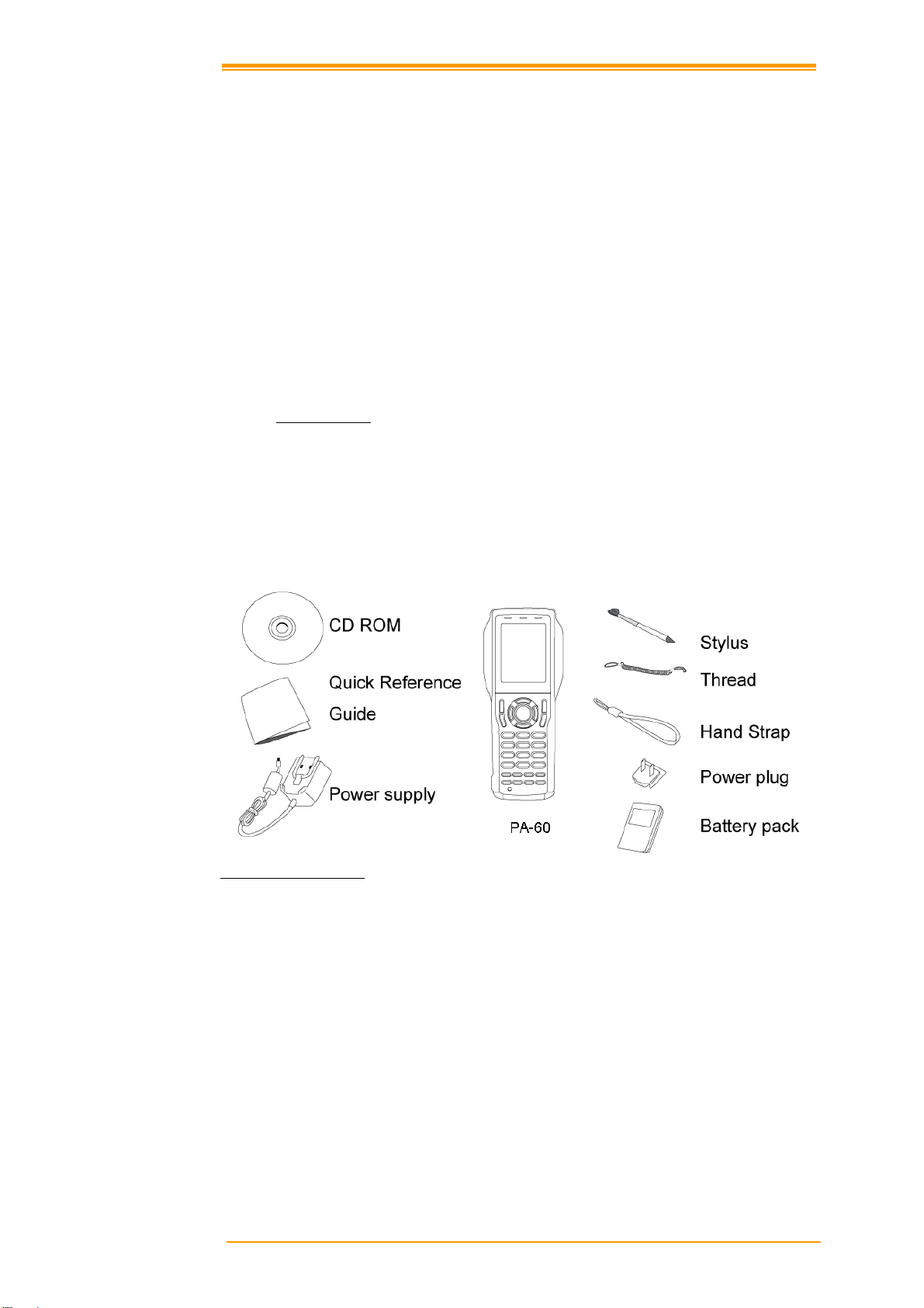
Depending on the configuration ordered, the PA-60 shipping container may include:
2.1.1 PDT Package
PA-60 Quick Reference Guide
Battery pack CD ROM
Hand strap Stylus
Power supply Thread
Power plug
Figure 2-1 Compact Package
User’s Manual 6
Page 13

2.1.2 Cradle Package
CRD-22 USB cable
Cradle USB cable
Figure 2-2 Cradle Package
Inspect the package contents for damage. If any item is missing or damaged, please contact the
Argox Technical Support Center immediately.
User’s Manual 7
Page 14
2.2 Detailed View
The pictures below provide informat i on on the PA- 6 0’s various buttons, ports and other
functions.
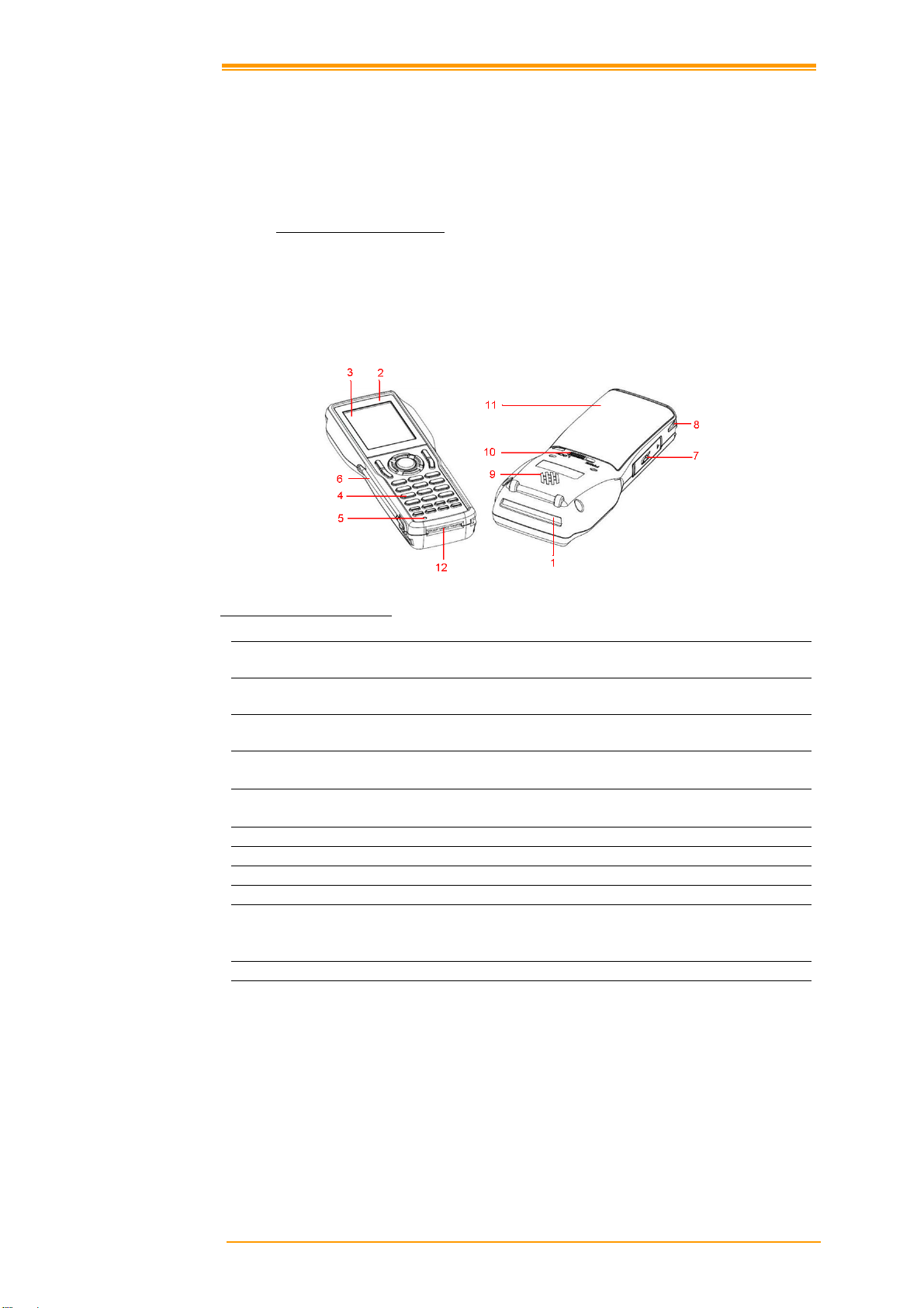
2.2.1 PA-60 Mobile Computer
Dimensions of the PA-60
168.8mm (L) x 70.1mm (W) x 34.0mm (H)
Details of the PA-60
Figure 2-3 The details of Terminal
1 Reading Window Optical beam of LED for barcode reading will be
emitted from here
2 LED Indicator
Touch Screen Use the stylus to perform specific actions on the
3
4 Stroke keys A total of 29 keys are provided to turn power ON
5 Reset switch Use a paper clip or other thin object to press the
6 Stylus
7 SD card slot
8 Hand strap hook Used to install the hand strap
9 Speaker
10 Main battery compartment lock Locks the main battery compartment cover in
11 Main battery compartment Holds main batteries
12 Power Contacts The terminal is used to supply power from
Can be used to indicate results, for example bar
code reading / status of communication
touch panel.
and OFF and for other operations.
RESET switch located inside the hole.
place. Terminal power is automatically cut if the
cover is removed.
Cradle.
User’s Manual 8
Page 15
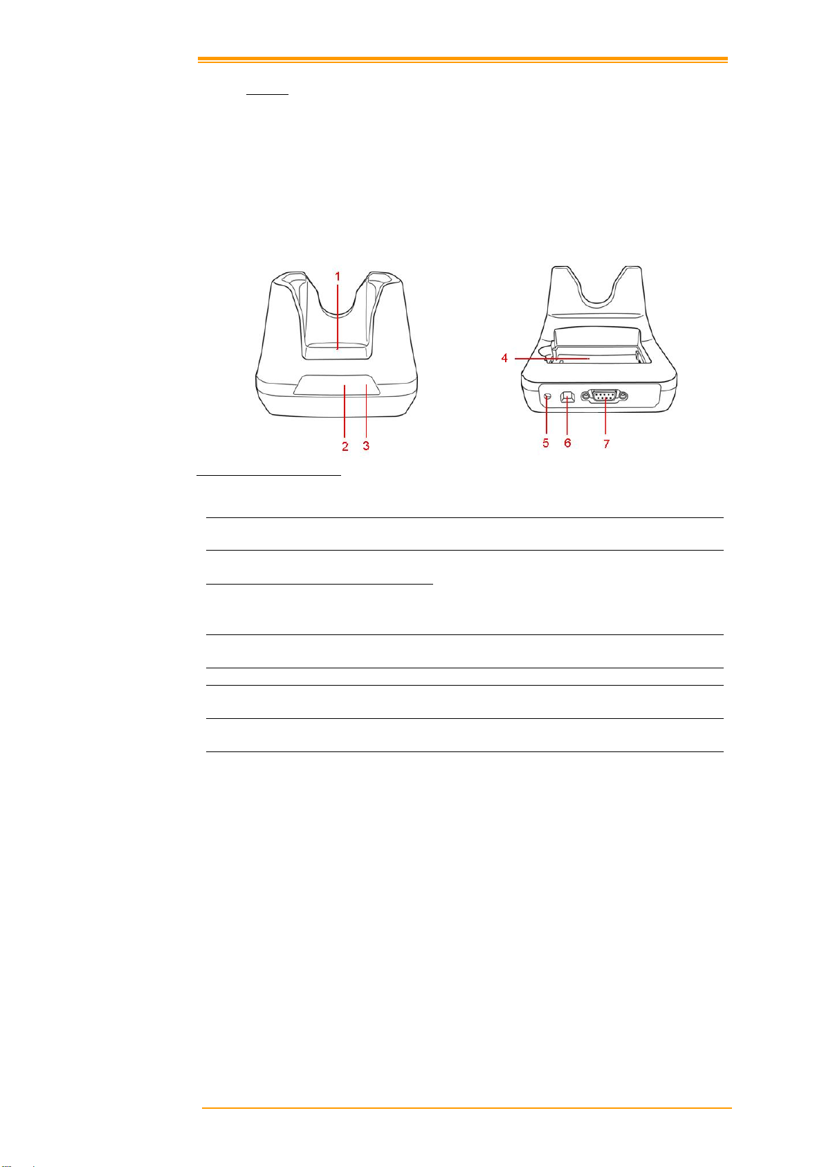
2.2.2 Cradle
Dimensions of the CRD-22 Cradle
162.4mm (L) x 112mm (W) x 93.9mm (H)
Details of the CRD-22 Cradle
Front Back
Figure 2-4 The Details of Cradle
1 Terminal Slot
2 Power LED Indicator Power indicates
Charging LED Indicator
3
Charging Slot
4
DC Input Socket Input for AC adapter
5
USB Socket
6
RS-232 Socket
7
Put the terminal on the cradle through this slot
for data transmission or charging
Indicates the charge status of the battery.
Green: no battery or charging complete
Red: battery is charging
For charging a spare rechargeable battery pack
For connecting to PC USB port through a
standard USB cable
For connecting to PC serial port through Argox
RS232 cable
User’s Manual 9
Page 16
2.3 Assembly
Follow the next steps to make your terminal ready for installation in a system that is described
further in the manual.
2.3.1 Terminal
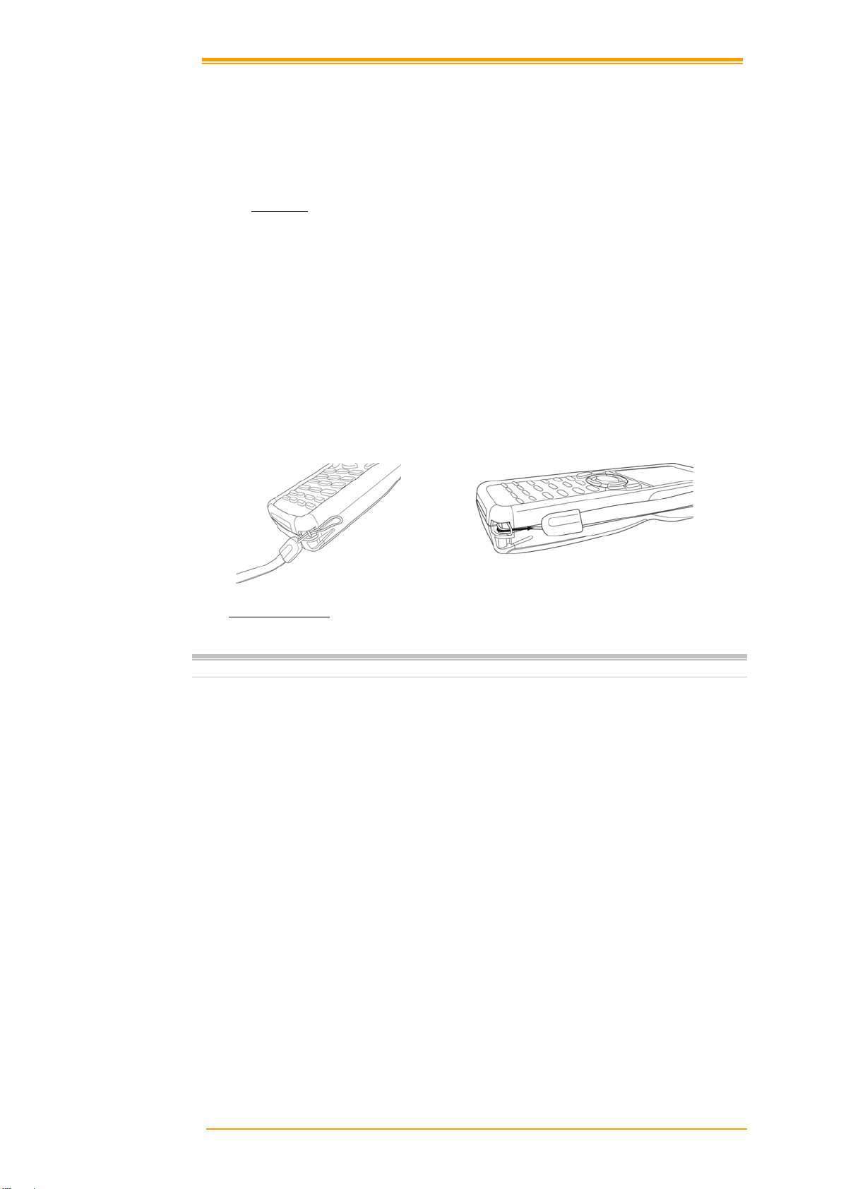
The hand strap protects the Terminal from being damaged as a result of it being dropped by
mistake during movement. Follow the procedure below to attach the hand strap.
To attach the hand strap
1. Fix the small cord of the strap around the pillar of the terminal.
2. Insert the handle of the strap in the thin loop.
3. The strap is fixed to the terminal.
4. Hold the hand strap around the wrist when carrying the terminal.
1
2
Figure 2-5 Hand Strap
Important: Do not swing the terminal around
Start with a full battery
1. To be sure of proper operation, it is advised to start with a full battery, charge the
battery pack according to the instructions in the nex t chapter.
2. Click the battery pack into the terminal as instructed in the next chapter.
User’s Manual 10
Page 17
2.3.2 Cradle
Power Connection
1. Attach the DC jack of the AC adapter into the socket of the cradle. Then connect
the AC adapter to the mains outlet. Both LED on the cradle turns green.
Battery charging
1. When the spare battery put in the charging slo t, the charging LED on the cradle
turns red during charging state and gets green when fully charged.
2. When the PA-60 terminal with the rechargeable battery placed in the cradle to
charge, the charging LED on the Terminal turns on in red and gets green when full
charged.
Terminal on cradle
Take notice that the PA-60 cradle is designed for the PA-60 or PA-20 terminal. No other type
of terminal can be placed into this cradle. This can cause damages to the connector on the
cradle.
Spare Battery
Charge LED
Figure 2-6 BatterCharging
Figure 2-7 Charging
User’s Manual 11
Page 18

2.4 Installing, Replacing and Charging Batteries
Wrong use of batteries might cause serious damage to the terminal or to the cradle. In order to
avoid damage, it is very important to take notice of the instructions.
Caution:
Required batteries:
The terminal needs both main battery and backup battery for operation.
Main Battery
Terminal: Rechargeable 3.7V 1950mAh Li-Polymer Battery
Gun type: Rechargeable 3.7V 4400mAh Li-lon Battery
Insert a fully-charged battery pack before use of the terminal.
Never remove the main batteries while the terminal is turned on.
Doing so may lose data in the terminal.
Use only recommended batteries.
When other batteries are used, defects or other problems can occur.
Before installing (new) batteries, please make sure you are using the
recommended batteries.
Use the right charger for batteries.
The rechargeable battery pack form Argox can be charged in the cradle
when either it is in the terminal or alone in the charging slot in the back
of the cradle.
The life of a battery pack is limited, and charging a battery pack
causes it to gradually lose its ability to maintain a charge. If your
battery pack requir es f r eque n t charging, it probably mea ns it is ti me
to purchase a new one.
Strictly follow the instructions for installing, charging, and removing
the batteries.
The products are not warranted for damage, defects, malfunction, or loss
of data, resulting from incorrect use of batteries.
User’s Manual 12
Page 19
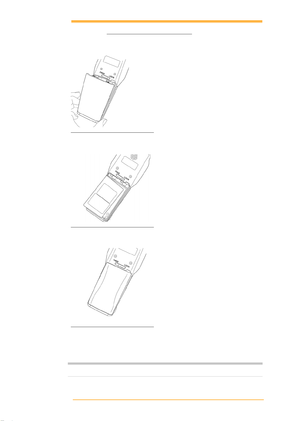
2.4.1 Installing / Replacing the Battery Pack
How to install or replace the main battery in the terminal
1 Slide the main battery compartment
cover lock to the FREE position and
remove the cover
Figure 2-8-1 Installing /Replacing The Battery Pack
2 Load a lithium-ion battery pack into the
main battery compartment in the
direction shown in the figure
Figure 2-8-2 Installing /Replacing The Battery Pack
Figure 2-8-3 Installing /Replacing The Battery Pack
Note:
Please follow the above procedure in reverse to reassemble the battery cover.
Be sure to turn the terminal OFF before you do this.
3 Attach the battery compartment cover to
the terminal and slide the main battery
compartment cover lock to the LOCK
position.
User’s Manual 13
Page 20

How to install or replace the battery in the gun grip
1 Turn the screw
Figure 2-9-1 Installing /Replacing The Gun Grip Battery
2 Open the cover
Figure 2-9-2 Installing /Replacing The Gun Grip Battery
User’s Manual 14
Page 21

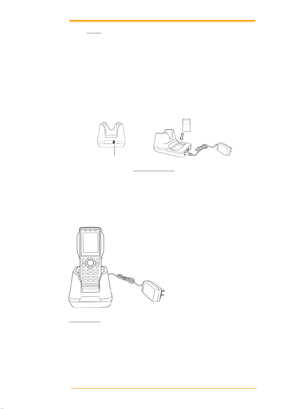
2.4.2 Charging the Battery Pack with Cradle
Figure 2-10 Charging with Cradle
a) Leaving the battery pack inside the Mobile computer
1. Connect the power adaptor to a power source
2. Plug in the connector of the po wer adaptor to the Cradle
3. Insert the Mobile computer into the Cradle
Note:
b) Placing the spare battery pack into the Cradle’s spare battery charging slot
1. Connect the power adaptor to a power source
2. Plug in the connector of the power adaptor with Cradle
3. Insert the battery pa ck into the Cradle’s spare battery slot
Note:
Caution:
When charging the battery pack, the Power LED on the Mobile computer turns
Red. After the battery pack is fully charged, the Mobile Computer Power LED
turns green.
When charging the battery pack in the Cradle’s spare battery slot, the Cradle
charging LED is Red. After the battery pack is fully charged, the LED turns green.
Ambient Temperature Ranges for the Battery Pack
Temperature ranges for battery pack use in the terminal, charging,
and storage is specified below. Temperatures outside these ranges
create the danger of deterioration of battery pack performance and
shortening of its service life, as well as fluid leakage and heat
generation.
Operating Temperature: -20°C to 50°C
Charging Temperature 0°C to 40°C
Storage Temperature: -20°C to 60°C
If the battery pack charge indicator does not light during charging,
remove the battery pack and then re-attach it. If this does not solve
the problem, it means that the battery pack is defective and needs to
be replaced.
Use only the specified battery pack.
Battery packs naturally d ischarge even when they are not loaded in
the terminal. Use a battery pack as soon as possible after charging it.
For best charging results, keep the cradle, terminal and battery pack
contacts clean by periodically wiping them off with a cotton swab or
dry cloth.
User’s Manual 15
Page 22
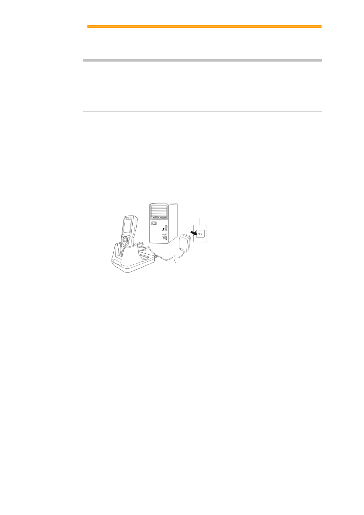
2.5 Installing in a System
Notes:
System Connection (Data Communication)
The PA series portable data mobile computers let you link to a host computer through RS-232
cable or the CRD-22 cradle for data communication.
2.5.1 Via CRD-22 Cradle
The CRD-22 cradle provides two methods for data transmission: through RS-232 cable (9-pin
connector for PC and 9-pin connector for mobile c omputer) or through USB cable.
Exercise caution at all times when working with AC-powered equipment. Turn off
your devices before installation.
Because of the special pin-out of the connectors, use the cables supplied by the
manufacturer.
Do not modify the cable provided by the manufacturer. If you need a special cable
for some cases, contact your supplier to purchase the right cables or technical
support.
Figure 2-11 Communication through Cradle
User’s Manual 16
Page 23
3 Operation of the Mobile Computer
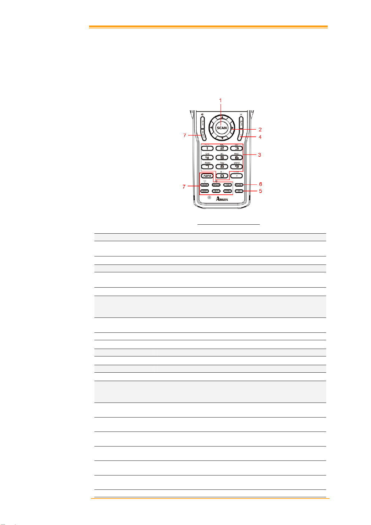
3.1 Keypad Description
The PA Series keypad consists of 29 rubber keys including one SCAN key.
Figure 3-1 Keypad Description
1. Scan key
Scan a bar code read operation
2. Navigation key
This cursor key navigates among applications.
3. 10-key pad
The function of these keys depends on whether the Terminal is in the character input
mode or the number input mode:
Character input mode:
Number input mode: Inputs the numbers 0 to 9 and the decimal point.
4.ENT key
5.Power key
6.Function keys (Combination key)
Keys that can be assigned any function. The following are the initial functions assigned to
these keys.
FUNC + (P1) Adjust speaker volume
FUNC + (P2) Adjust LCD Backlight
FUNC + (BKSP) Turns the keypad Backlight ON / OFF
FUNC + (SPACE) shortcut for Windows Start key
FUNC + (TAB) Touch Panel calibration
FUNC + (1) ~(9) Shortcut for user define key or application
(P1) ,(P2) Shortcut for user define key or application
User’s Manual 17
Input alphanumeric and symbols.
Enter key.
Turns power ON and OFF.
Page 24

7.Control keys
ALPHA Switches between the number input mode or the character input mode.
When [1] on the screen Icon-Bar indicate that the input mode at number
input mode. (Default on number mode)
When [a] or [A] on the screen Icon-Bar indicate that the input mode at
character input mode.
ESC Escape key
BKSP Backspaces key
SPACE Space key
TAB Tab key
ALT Alt key
CTRL Control key
SHIFT Shift key
User’s Manual 18
Page 25

3.2 Installing SD card
Caution:
3.2.1 Inserting SD card into the PA-60
1. Open the SD cover.
2. Insert a correctly oriented SD card.
3. Close the SD cover.
Note:
Make sure you have fully charged the battery before turning the unit on.
When removing an SD card, please press “push” first.
SD Installation
Remove the cover
Figure 3-2 Installing SD Card
User’s Manual 19
Page 26

3.3 Configuring PA-60 Settings
3.3.1 Calibrating Touch Screen Alignment
Calibrating the PA-60
This screen can be accessed at any time by
pressing the hot key “FN” and “TAB” key. Or
by accessing the menus and tab in order of
Start → Settings →Control Panel→ Stylus
→ Calibration.
Figure 3-3 Calibration
Whenever the response of the touch screen is poor, or the operations executed do not match
your tapping on the touch screen, please recalibrate the alignment of the touch screen using the
following method.
A. Press the stylus against the center of the
target mark (+ mark) as indicated on the
screen. The screen shown to the right
appears after you press the stylus against
the target at five different locations.
B. Press the Execute key or tap anywhere on
the touch screen
Figure 3-4 Calibration
User’s Manual 20
Page 27

3.3.2 Adjusting LCD Backlight Brightness
You can use the following procedures to adjust display brightness to make it easier to read
under different lighting conditions.
Press the “FN” + “P2” key and then press the “▲” or “▼” key. Press the “▲”
key adjusts brightness for a lighter display, while pressing the “▼” key adjusts
brightness for a darker display.
To continue making adjustments, press the “▲” or “▼” after pressing the “FN” +
“P2” key.
Brightness settings are also made by accessing the menu and tab in order of Start
→Settings→Control Panel→Timeout&Brightness→Brightness.
3.3.3 Adjusting Sound Volume
You can use the following procedures to adjust sound to make it easier to hear under different
working conditions.
Press the “FN” + “P1” key and press the “▲” or “▼” key. Press the “▲” key
adjusts for a louder sound, while pressing the “▼” key adjusts for a softer sound.
To continue making adjustments, press the “▲” or “▼” after pressing the “FN” +
“P1” key.
Sound settings are also be made by accessing the menu and tab in order of Start
→Settings→Control Panel→Volume & Sounds
3.3.4 Using the Stylus
The stylus is located next to CF cover or hand-strap on the rear of the PA-60 as illustrated in
figure 2-3 PA-60 Back view (page 8). The stylus functions the same as a mouse on a PC. Use
the stylus to:
Navigate the display, select menu items and open optional applications.
Tap the characters on the soft keyboard panel
Hold the stylus on the screen and drag across the screen to select a list of multiple
items.
Caution:
Never use a pen, pencil, or other sharp object on the display to avoid
damaging the touch screen.
User’s Manual 21
Page 28

3.4 Entering Information
To enter information:
Use the keypad
Use the keyboard input panel (soft keyboard) to enter text.
Scan bar code data into data fields.
Use Microsoft ActiveSync to synchronize or copy information form the host
computer to the PA-60. For more information on ActiveSync, refer to Chapter 6.
3.4.1 Entering Information Using a Keypad
The alphanumeric keypads produce the 26-character alphabet (A-Z), number s (0-9), function
keys and assorted characters. The keypads default characters/functions are printed white.
3.4.2 Entering Information Using the Keyboard Input Panel
Use the keyboard input panel (soft keyboard) to enter information in any program. To launch
the keyboard input panel, press the button on the taskbar. Tap a key to enter a value. Tap a
key board input panel button to display or hide the keyboard input panel.
Figure 3-5 Input Panel
3.4.3 Entering Data via the Bar Code Scanner
The sample bar code scanner application scans data into data fields in the same way data is
entered via the keypad.
User’s Manual 22
Page 29

3.5 Power Management
3.5.1 Power Status Indication
Checking main and Backup Battery Statue
Enter “Power Properties”
If the above mentioned “Plug” or “Battery” icon is displayed, double tap this icon to bring up
the “Power Properties” screen.
Or, select Settings/ Control Panel from the Start menu and then double tap the “Power” icon
to display “Power Properties”.
Figure 3-6 Settings/Control Panel
Check Battery Status:
The battery menu item shows the status of the main and backup batteries.
Figure 3-7 Power Properties
User’s Manual 23
Page 30

Five different icons are displayed on the status bar to indicate the on-board power status.
Icon Description
No icon:
“Plug” icon:
“Charging” icon:
“Battery Low” icon:
“Battery Very low”
icon:
You must charge the battery when the battery “Very Low” icon is displayed. If the “Very
Low” icons still show after charging, please contact Argox Technical Support.
Indicates there is no external power supply to the PA-60 but
the battery power status is good.
Shows external power is in use. The PA-60 is either
plugged-in via the DC 5V/2.5A power adapter or in the
cradle.
Indicates that the battery is charging.
Shows there is no external power supply, the battery charge
is low.
Indicates the battery is very low. Stop operation and charge
the PA-60 immediately.
User’s Manual 24
Page 31

3.5.2 Saving Battery Power
Automatic shut-down of the PA-60
The PA-60 enters idle mode when there is no task or if all tasks are waiting for input. In
default setting, the PA-60 automatically turns itself off if idle for 3 minutes and when there is
no external charging power. Press the power button to return the PA-60 to the same point at
the time of automatic shutdown.
In Power Properties, select “Schemes”. Customize automatic shut off time by tapping the
arrow to select from a list of time periods. The available time periods are 1, 2, 3, 4, 5, 10, 30
minutes and never.
Activate this function when the PA-60 is plugged into the power adapter or placed in its cradle
by tapping the check box and then tapping the arrow to select from a list of time periods. The
available time periods are 1, 2, 3, 4, 5, 10, 30 minutes and never.
Figure 3-8 Power Properties
Backlight Setting
Because the power consumption of the LCD backlight is high, turn off the backlight function
when it is not necessary. If a backlight is required, set “automatically turn off the back-light.”
To change the backlight setting, select Settings / Control Panel from the Start menu, and then
double tap the “Timeout & Brightness” icon.
Figure 3-9 Backlight Setting
User’s Manual 25
Page 32

Tap the “Backlight” menu item to display the following 2 selections:
Automatically turn off the backlight when using battery power:
Tap the check box to toggle this function. Available idle times are: Off, Micro, Fine, Normal
and Super.
Automatically turn off the backlight when using external power:
Tap the check box to toggle this function.
Available idle times are: Off, Micro, Fine,
Normal and Super.
Figure 3-10 Timeout & Brightness
3.5.3 Suspend Mode
The PA-60 will go into suspend mode when it is idle for a period of time. Customize the idle
duration using the Power control panel (refer to Figure “Schemes Tab”). Suspend mode
appears just like you have turned the unit off. Press the
the
Use the Battery Power control panel to set the duration to switch to Suspend mode when the
system uses battery power. This saves battery power when the PA-60 is not in use.
Entering Suspend Mode:
The following puts the PA-60 in suspend mode:
key again for the PA-60 to resume its previous state.
Press
The duration timer for “Switch state to Suspend” expires, which indicates that
there has been no use for a specified of time.
The battery pack di scharges completely.
Tap Start > Suspend
key while the unit is on.
key to suspend the PA-60. Press
User’s Manual 26
Page 33

Figure 3-11-1 Suspend Mode setting Figure 3-11-2 Suspend Mode setting
Tap here to put the PA-60 into suspend mode
3.5.4 Resume
Press
Waking the PA-60
The default wakeup conditions define what actions wakeup the PA-60. These setting are
configurable and the factory default settings are subject to change / update.
Status Description Condition for Wakeup
Power Off When the PA-60 is set to suspend mode by pressing
Auto Off When the PA-60 enters suspend mode by automatic
key to suspend or resume (wake up)
, this action wakes the PA-60.
power-off, this action wakes the PA-60.
Press
Press button
button
User’s Manual 27
Page 34

3.6 Resetting the PA-60
If the PA-60 stops responding to input, reset it. There are two reset functions, warm boot and
cold boot. A warm boot restarts the PA-60 by closing all running programs. All data that is not
saved is lost.
A cold boot also restarts the PA-60, but erases all stored records and entries from RAM. In
addition it returns formats, preferences and other settings to the factory default setting.
Perform a warm boot first. If the PA-60 still does not respond, perform a cold boot.
3.6.1 Performing a Warm Boot
To perform a warm boot:
a. Press “Reset
b. The PA-60 demo window appears.
Caution:
Files that remain open during a warm boot may not be retained.
3.6.2 Performing a Cold Boot
A cold boot restarts the PA-60 and erases all user stored records and entries from RAM. Only
perform a cold boot if a warm boot does not solve the problem.
Caution:
To perform a cold boot:
1. Press the “Reset
2. Calibrate the touch screen. See instructions on calibrating the PA-60 screen in chapter 3.
Cold boot resets the PA-60 to the default settings. All added applications and all
stored data are removed. Do not cold boot without support d e sk ap proval.
or buttons. As the PA-60 initializes the Argox welcome screen appears for about a minute.
”. Do not hold down any other keys or buttons.
” and “Power ” keys together. Do not hold down any other keys
User’s Manual 28
Page 35

3.7 Flash Disk
Flash memory is a re-writable location in which to store 256MB of programs and data files.
The benefit of this feature is that files and programs saved in Flash Memory are unaffected by
the PA-60’s power status.
Note:
Caution:
3.7.1 Flash Disk Location
To access the contents of Flash Disk storage:
The Flash Disk storage memory persists for all reset (warm/cold reboot)
conditions and software/firmware updates. We strongly recommend installing all
applications, applets, programs, and important data files to the Flash Disk
location.
If an application or a data file is installed or saved in RAM, a cold reset will
result in the loss of that application or data file.
Double-tap the My Device icon on the desktop
Double-tap the Flash Disk icon to view Flash Disk.
Figure 3-12-1 My Device screen Figure 3-12-2 Flash Disk
3.7.2 Saving to Flash
To save an application or data to Flash
Memory from your current application,
select File → Save As → navigate to the
Flash Disk location and save it.
Figure 3-13 Save to Flash Disk
User’s Manual 29
Page 36

3.7.3 Flash Disk Size
The size of the Flash Disk varies depending
on the size of the system firmware.
A. Inside the Flash Disk directory, tap File
→ Properties
B. The Flash Disk Properties dialog:
The number following Free is the amount of
memory currently available on your device.
Figure 3-14 Flash Disk Properties and Size
User’s Manual 30
Page 37

3.8 Bluetooth Enable Setting
3.8.1 Please enable Bluetooth first like Figure 3-15.
Figure 3-15 Enable Bluetooth
3.8.2 After enable Bluetooth, please double click BT Icon like figure 3-16
Figure 3-16-1 BT Icon Figure 3-16-2 Show BT
User’s Manual 31
Page 38

3.8.3 On Bluetooth manager screen, select file new connection like Figure 3-17.
Figure 3-17 Bluetooth connection
3.8.4 Bluetooth has four functions to choose like Figure 3-18.
Figure 3-18 Bluetooth Explorer
User’s Manual 32
Page 39

3.8.5 First function is Pair with remote device, after press next button.
It will start to search devices. Select a device and press Pair button; it needs to enter
Bluetooth PIN code like Figure 3-19.
Figure 3-19-1 Bluetooth Pairing Figure 3-19-2 Bluetooth Pairing
3.8.6 After PA-60 check pin code with device. PA-60 will appear a pop window and show
success message like Figure 3-20.
Figure 3-19-3 Bluetooth Pairing Figure 3-19-4 Bluetooth Pairing
User’s Manual 33
Page 40

3.8.7 Second function is serial Port which communication with device via com port like
Figure 3-20.
Figure 3-20
3.8.8 After press next button, it will start to search device like Figure3-21.
Figure3-21
User’s Manual 34
Page 41

3.8.9 After press Connect button, it will appear a connection with SPP mode like Figure 3-22.
Figure 3-22
3.8.10 Third function is File Transfer like Figure 3-23
Figure 3-23
User’s Manual 35
Page 42

3.8.11 After press next button, it will start to search device and it needs to enter pin code
like Figure 3-24
Figure 3-24
3.8.12 After checking pin code with the connect device. PA-60 will enter FTP mode like
Figure 3-25.
Figure 3-25
User’s Manual 36
Page 43

3.8.13 On Bluetooth manager screen, it will add a FTP connection like Figure 3-26.
Figure 3-26
3.8.14 The latest function is ActiveSync connection. The fun c tion can connect with
computer via ActiveSync.
Figure 3-27
User’s Manual 37
Page 44

3.8.15 After press next button, it will start to search device.
Figure 3-28-1 Figure 3-28-2
3.8.16 PA-60 will add an ActiveSync connection on Bluetooth manager screen. It will
synchronize with computer.
Figure 3-29
User’s Manual 38
Page 45

3.9 WLAN configuration step
For models using the 802.11 b/g/n radio, you can find information about the applet for
radio configuration: http://http://www.summitdata.com/SCU.html .
3.9.1 Please enable Wi-Fi first like Figure 3-30-1. After enable Wi-Fi, summit icon appears
as below. Figure 3-30-2
Figure 3-30-1 Figure 3-30-2
User’s Manual 39
Page 46

4 Scanning
The PA-60 has an integrated CCD scanner that reads all major bar code labels with excellent
performance. The trigger key is located in the middle of the unit. Press this key to activate the
CCD scanner.
4.1 Scan Configuration
When it is necessary to change the default barcode symbology for a different application, use
Scan Configuration to change default symbology, place delimiter characters behind scanned
data, and save the settings.
Run this program from \Programs\Scanner\Scan Configuration.exe which is also accessible
via “Setting\Control Panel\” on the Start menu.
Figure 4-1-1 Scan Configuration
Figure 4-1-2 Scan Configuration
User’s Manual 40
Page 47

Figure 4-1-3 Scan Configuration
Figure 4-1 -4 Scan Configuration
After you change settings, go to the “Setting” page and press the “OK ” button to configu re, or
press “Reset” to return to the scan default settings. The “Download” page allows you to update
scan firmware.
User’s Manual 41
Page 48

4.2 Scan driver
Scan driver lets you put data into Microsoft WordPad. Open scan driver and the scan module
Figure 4-2-1 Scan Demo
Figure 4-2-2 Scan Demo
powers on the scanner. You can then scan barcode. To turn off the power, press “Exit” on the
task bar.
User’s Manual 42
Page 49

4.3 Scan test
The PA-60 has a built-in Scan Test.exe program that allows you to test the barcode scan
function. Scan Test.exe is located in directory \Programs\Scanner\ Scan Test.exe.
This program shows barcode type and barcode data when pressing the “Scan” key.
Figure 4-3-1 Scan Test Figure 4-3-2 Scan Test
User’s Manual 43
Page 50

4.4 Reading barcode
Note:
Observe handling precautions.
Make sure the mobile computer is installed according to instructions.
Never remove the main batteries or battery pack while the mobile
computer is turned on. Doing so can cause loss of data in the mobile
computer.
Avoid looking directly into the LED light beam emitter, or pointing the
LED light beam directly into someone’s eyes.
Position the LED light beam over the bar code from margin to margin and pass the scanner
downward over the bar code, as shown in the scan position illustration
Good read scan position
Incorrect read scan positions
Figure 4-4 Scan Test
The scanning sequence is defined by the user’s application. A typical sequence is:
Point the mobile computer at the barcode and press the Trigger key
.
Point the LED lightbeam at barcode as shown in the scan position illustration above.
The scanner reads the barcode and the results are indicated.
A “Good Read” means that the scanner has effectively recognized and decoded the bar code.
In most cases, the application program provides an indicator signal to indicate a good read.
If the read is incorrect, try again paying close attention to the instructions.
When reading a small bar code, decrease the distance between the mobile computer and the
bar code. For larger bar codes, position the mobile computer so th at the bar code fits into the
LED light beam. When reading a very high density bar code, decrease the distance between
the mobile computer and the bar code. For a low density bar code, increase the distance
between the mobile computer and the bar code.
User’s Manual 44
Page 51

4.5 Barcode reading problems
When the barcode can not be read, try
the following:
1. Change the angle between the
barcode and the mobile computer.
2. Change the distance between the bar
code and the mobile computer.
If the bar code is larger than the
LED light beam, try moving the
mobile computer a bit further away
from the bar code.
User’s Manual 45
Page 52

5 Utilities
5.1 Function Key Setting
AP Settings Tab
To assign your favorite application program from F1 to F9 hot keys:
1. Choose F1, F2, F3 … or F9 from pull-down list.
2. Tap “Define” inside the “Function Key Setting” applet.
3. Select the application program you want from program list, and then choose “OK”.
4. Tap the Apply tab to complete setting.
5. Tap the Default tab to return to default setting.
Figure 5-1 Function Key Setting
User’s Manual 46
Page 53

5.2 Timeout & Brightness
Backlight setting is a tool for changing the LCD backlight. If you wish to save power use this
program to change LCD backlight settings. This application supports battery power backlight
and external power backlight.
Figure 5-3 Timeout & Brightness
User’s Manual 47
Page 54

6 Software Applications
The PA-60 includes software applications
such as Internet Explore, Media player,
Microsoft WordPad, Remote Connection,
Transcriber, and Windows Explore.
Figure 6-1 Progr ams Implemented
6.1 Internet Explorer
With Internet Explorer, you can view Web or
intranet Web pages on your device. You will
need to use WLAN to connect to an Internet
Service Provider (ISP) or network.
Figure 6-2 Internet Explorer
User’s Manual 48
Page 55

6.2 Media Player
The PA-60 comes with Media Player for
Windows CE 5.0 installed.
Open Media Player by selecting Start →
Programs →Media Player from the
desktop.
Select File → Open to open a new media
file.
Please refer to www.microsoft.com
additional information and help with
your Microsoft Windows Media Player.
Figure 6-3 Media Player
for
6.3 Microsoft WordPad
You can create and edit documents and
templates in WordPad, using buttons and
menu commands that are similar to those
used in the desktop version of Microsoft
Word. You can work with files Normal or
Outline view.
WordPad documents are usually saved
as .pwd files, but you can also save
documents in other file formats, such as .rtf
or .doc.
6.4 Remote Desktop Connection
Using Remote Desktop Connection, you can
log on to Windows Mobile computer Server
and use all programs installed on this server.
For example, instead of running Microsoft
Pocket Word, you can run the desktop
version of Microsoft Word.
Figure 6-4 Microsoft Wordpad
FIGURE 6-5 REMOTE DESKTOP CONNECTION
User’s Manual 49
Page 56

6.5 Transcriber
Features:
Microsoft Transcriber is the natural
handwriting recognition solution for
your Windows CE device. It recognizes
words from its integrated dictionary,
and allows you to write in cursive, print
or mixed handwriting.
The letter Shapes Selector (note 1) is
for optimizing recognition to your own
handwriting style
Transcriber works transparently in the
background of all Windows CE
applications providing handwriting
input, while taking away no precious
screen space.
Figure 6-6 Transcriber
6.6 Windows Explorer
Windows Explorer works almost the same
on your PDA as it does on your PC. See the
topics below for information about the
difference in Windows Explorer on your
device.
Figure 6-7 Windows Explorer
User’s Manual 50
Page 57

7 Communication
The Argox PA-60 lets you link to a host computer via RS-232 or USB port for data
communication. This chapter gives an overview of the PA-60’s communication capabilities.
7.1 ActiveSync
To exchange data between your desktop computer and the PA-60, Microsoft ActiveSync must
be installed on your desktop computer.
With Microsoft ActiveSync you can:
Transfer data
Back up and restore PA-60 data.
Add programs to and remove programs from the PA-60.
This chapter introduces Microsoft ActiveSync version 4.5 ActiveSync provides a user-friendly
interface and it can be downloaded free of charge from Microsoft’s Website.
7.2 Installing Microsoft ActiveSync
Before beginning installation, carefully read the following:
Because you will restart your computer during installation, save your work and quit all
programs before you begin.
To set up your communication settings, a PA-60 serial cable is required to connect the PA-60
to your host computer.
If you run the Windows NT operating system with a service pack, you will be informed during
setup that you may need to reinstall the service pack. Try connecting first, and if unsuccessful,
reinstall the latest service pack.
Basic PC specifications for the installation of ActiveSync are as follows:
OS Microsoft Windows XP/2000/ M E/ 98, o r hi g her ve rsi o n pr o gram than
SP6 Windows NT Workstation 4.2
Application To be able synchronize data such as email, calendar tasks and notes
between OT-80 and a desktop or notebook, you need to have a higher
version than Microsoft Outlook 2000
Browser Microsoft Internet Explore 4.21 SP1 or higher
Hard disk Free hard disk space more than 65MB (Actual required space is
according to selected functions and your current system configuration)
Communication port 9 pin or 25 pin communication port (for adapter, 25-pin port is needed)
USB port (available only for Windows 98/Me/2000/XP)
Graphic card VGA graphic card or compatible video graphic adapter supporting
resolution of 256 colors or higher
Keyboard
Microsoft mouse or compatible input devices
CD-ROM drive
User’s Manual 51
Page 58

Installation
Follow the installation procedure below to install Microsoft ActiveSync, connect your PA-60
to your desktop computer, and establish a partnership for synchronization (if desired):
1. Download the executable program “mswrd832.cnv” from CD. Execute this program.
2. Select the folder into which Microsoft ActiveSync will be installed. If you choose not to
download into the displayed default folder, click the Change button.
3. After you’ve selected the folder, click Next to set up Microsoft ActiveSync. After you’ve
installed Microsoft ActiveSync and restart your computer.
7.3 Connecting the PA-60 to ActiveSync
Connect the PA-60 to a desktop PC using a USB cable. Make the partnership between the
desktop PC and PA-60 through ActiveSync, and then proceed with the synchronization of the
desktop PC and PA-60. Use a USB cable to link the PA-60 to the desktop PC.
The table below shows available communication devices (USB, serial) according to operating
system.
Supporting operating system
Desktop PC OS Connection
methods
USB Not available Available Available Not available
Serial Not available Available Available Available
Connect a desktop PC and the PA-60 with a cable as follows:
4. Connect a USB cable to the USB port of the desktop PC.
5. Insert the cable into PA-60 mobile computer. The PA-60’s PC connection program runs
automatically and Microsoft ActiveSync in the desktop links them together.
6. To set up a connection, the “New Connection” set-up wizard appears on the desktop
computer. Set-up methods are discussed in the following section.
Windows 95 Windows 98 Windows
2000/XP
Windows NT
User’s Manual 52
Page 59

7.4 Setting up a Partnership
When you first connect the PA-60 to the desktop computer, Microsoft ActiveSync asks if you
are going to set up a partnership. Once the partnership set-up is finished, you can synchronize
data with the PA-60. While the PA-60 can set up the partnership with two desktop computers,
email messages can be received only through one computer.
To set-up a partnership:
1. Insert the PA-60 into the docking cradle connected to the desktop PC. It automatically
starts the New Partnership wizard on the desktop PC screen. When it asks if you would
like to set up the partnership, select Yes and click Next.
Figure 7-1 Set up a Partnership
2. Key in the name of the device (for instance, Windows CE1, MyPDA, etc.) then click
Next.
3. If the PA-60 has already set up a partnership with another desktop computer but no
longer uses it, select “Yes, I want to synchronize with only this computer” in the
dialog box named “Select Number of Partnerships.” It removes the other partnership setup so that the PA-60 no longer recognizes the previous desktop compu ter. Click Next.
4. The window for setting up synchronization appears. To synchronize specific kinds of
data, select the item then click Next. Most popular items include Calendar, Contacts,
Tasks, and Inbox. We recommend you select and use these items. In the item list, two
types of email items are available: Inbox and Inbox. While the inbox is an email program
provided by Microsoft Corporation, Inbox is offered by a software provider. In the PA60, Inbox offers special functions such a connecting to “Today” set-up function button,
etc.
5. Complete the set-up process by clicking End.
When the partnership set-up between desktop PC and PA-60 is completed, ActiveSync
automatically synchronizes the selected data.
User’s Manual 53
Page 60

7.5 Connecting the PA-60
7.5.1 Synchronizing Data
If the Microsoft ActiveSync window appears in the desktop PC, click the option icon and
“Sync options,” “Sync Mode,” and “Rules” appears.
“Sync options” lets you select an item to synchronize. “Sync Mode” enables you to choose
synchronization methods. According to the selected mode, there are 3 methods:
1. Continuously while the device is connected: (Default) Connect the PA-60 to the
desktop computer. ActiveSync immediately starts synchronization and synchronizes
according to the user’s input of changes in the desktop computer or PA-60.
2. Only upon connection: Connect the PA-60 to the desktop computer. ActiveSync
immediately starts synchronization. If you want to carry out the synchronization after the
first synchronization on a manual basis, click Sync.
3. Manually: ActiveSync will not run automatically. For synchronization, click Sync.
Synchronization is the process of updating PA-60 and desktop PC after comparing data. Any
files including personal organizer management data, email message, etc. in the PA-60 can
synchronize with files in the desktop PC.
7.5.2 Solving Problems during Synchronization
When a problem occurs during the synchronization process, it is marked as “Not completed”
in both ActiveSync and the PA-60. You can solve the problem at your convenience.
There are various reasons for failure of ActiveSync to carry out synchronization. For instance,
if the computer cannot access Microsoft Outlook information due to a server failure,
ActiveSync cannot synchronize items such as Calendar, Contacts, Tasks, and Inbox. Or else
the problem stems from changed items in the PA-60 and the desktop PC.
By modifying the problem-solving settings, you can have ActiveSync not register the problem
as “not completed item” instead, if you select the PA-60 or desktop PC as default version,
ActiveSync automatically updates the information contained in the other computer. If you do
not want to solve the problem manually, you can modify the problem-solving setting to have
ActiveSync always use the PA-60 or desktop PC version.
1. Click options then click tap Rules.
2. Select the item of choice from Conflict Resolution.
For those items that cannot complete synchronization without user intervention, ActiveSync
and portable device display them as “not completed”.
1. Connect PA-60 to the desktop computer and carry out synchronization.
2. When there are no complete items, click Resolve in the Tools menu.
3. Follow instructions on the screen. The dialog box differs depending on the problem.
User’s Manual 54
Page 61

7.5.3 Searching PA-60 Contents from a Desktop PC
If the PA-60 is connected to a desktop PC, you can use ActiveSync on the desktop PC to see
the contents of the PA-60. Click Explore from the file menu of ActiveSync. The content of the
PA-60 is displayed on the window of Mobile Device.
Use ActiveSync to see the files in the PA-60 as follows:
1. Connect the PA-60 to the desktop PC
2. Explore in ActiveSync. It open the Mobile Device folder in Windows Explorer
3. Applying the same method, check the files in the device in other Windows Explorer
If you double click folders in Mobile Devices, it may take several seconds to open the folder.
While browsing the folders, you can carry out cut, paste, and copy by dragging file icons. In
the desktop PC, you can get access to the content of the PA-60 using Windows Explorer. If
you choose Files during the partnership set-up, Windows CE My Documents is created in the
My Documents folder. If you use Windows CE My Documents in the desktop PC, you can
easily access the My Documents folder in the PA-60.
User’s Manual 55
Page 62

8 Overview of Microsoft Windows CE 5.0
This chapter describes Microsoft Windows CE 5.0, the operating system for the PA-60
This introduction to Microsoft Windows CE 5.0 includes:
1. How to use the main Windows
2. How to use a taskbar
3. How to use settings
8.1 Main Windows
When you turn on PA-60, you will see the
main Windows of Window CE 5.0, which
is similar in appearance to Windows XP.
The main window consists of a background
screen and taskbar.
Figure 8-1 Main Window
The screen shows short cut icons for the main programs of Microsoft Windows CE 5.0. A
description of the icons follows:
My Device:
Shows the internal configuration of the
PA-60 and the folders and files it contains.
Figure 8-2 My Device
User’s Manual 56
Page 63

Recycle bin:
Completely delete or restore files and data. This folder saves deleted files from Windows
Explorer or the background screen. You can completely empty or restore files in the recycle
bin.
Caution:
Taskbar
Windows CE 5.0’s taskbar is designed to be simple and user-friendly. The picture below
shows the configuration of the taskbar.
Start Icon
Start icon is the starting point for the PA-60 program. If you point at the start menu with the
stylus pen, you can see various menus including program, bookmark, document, setting, help,
and operation. If you choose each menu, detailed executable programs appear as in the picture
below. If you choose and press, you can run the program of you r choice. Windows CE 5.0’s
start menu is similar to that of Windows on a desktop PC.
Once you have emptied the recycle bin, you cannot restore the files and data
previously in the recycle bin.
Figure 8-3 Start Icon
User’s Manual 57
Page 64

8.2 Taskbar
Taskbar shows a variety of information including keying in characters, battery, network
connection, status of running programs, etc.
If you press and hold the taskbar with the stylus, the right button function menu appears.
The right button function menu is composed of task manager and features. If you select the
taskbar and start menu feature, general option menus such as “always place above, “automatic
hiding,” “Watch display”, etc. You can choose the check box of desired options and use them.
The following explains the function of icons appearing on the task bar.
Transcriber:
When you want to key in characters when making a document or setting, start Transcriber.
Using the stylus to draw characters you want on the input panel, this program recognizes the
characters and transform them into typeface characters. To start the Transcriber, run the
program as the following order: start → program →Transcriber.
The picture below shows how the Transcriber works in keying in characters on Microsoft
Word Pad. When Microsoft Transcriber is running, you will see the “hand with a pen” icon
located in the taskbar. When Microsoft Transcriber is active the “hand with pen” icon shows a
dark background.
Figure 8-4 Transcriber
Keyboard: Press this icon to activate the keyboard input
User’s Manual 58
Page 65

Upper / lower case Selection:
Press this icon to select upper and lower case letters. If you select upper case, capital letters
and characters appear on the number key pad. It serves the same function with the Shift key.
Hot key Selection:
If you use hot key such as “z”, “x”, “c” and “v”, you can carry out Cancel, Cut, Copy, and
Paste, respectively. To change the features of the soft keyboard, select keyboard in Go to Start
→ Setting → Control Panel → Input Panel and click the option you wish to set up.
Input Method:
To carry out character key-in using [keyboard] inpu t, press keyboard icon on the taskbar. You
can also key in by activating Transcriber in the following order: Start → program →
Transcriber. Press the keyboard once, it appears on the screen. Press again and it disappears.
Status Indicator Icon:
The following is a list of icons that appear in the taskbar’s status area.
Icon Description
Battery capacity is low
Battery is charging
Linked to desktop PC through USB
Show network connection status.
Show Internet connection status via WLAN
User’s Manual 59
Page 66

8.3 Setting up the PA-60
You can set up various configurations of the PA-60 such as date/time, Network, Display,
Volume, Power, System, etc. at the control panel.
Figure 8-5 -1 Control Panel
If you press Start → Setting → Control Panel, the control panel window appears. In the View
option in the menu, you can change the view mode into large icons, small icons, details or to
arrange icons. The control panel appears as below:
Figure 8-5-2 Control Panel Figure 8-5-3 Control Panel
User’s Manual 60
Page 67

8.3.1 Certificates
Application programs use certificates to ensure reliability and safe communication.
Figure 8-6 Certificates
Authorized certificate providers issue certificates that are valid for a specified period.
Windows CE 5.0 manages several certificate storages.
1. Select Go to Start → Setting → Control Panel.
2. Double click a certificate to run.
Select certificate storage for browsing or correcting through the storage tap list.
My certificate: This saves the user’s personal certificate to identify the user.
Other certificate providers: Middle certificate providers establish chains of reliability.
Reliable certificate providers: Includes the top quality certificates.
3. To add certificates or secret keys in the selected storage, press the Bring button then
select the way to bring certificates or keys. You can select them from files or a smart card.
4. To see details of selected certificates such as extension, expiration date, etc. press the
View button.
5. To delete the selected certificate from storage, press Delete button.
User’s Manual 61
Page 68

8.3.2 Date/Time
This screen sets date, time, standard time zone, watch and alarm.
Figure 8-7 Date/Time
Date/Time
You can set standard time zone, year, day and time. Set as follows:
1. Press the down arrow in the standard time zone until it reaches your location. If the
previously set value is appropriate, move on to the following.
2. Select year and month in the calendar. If the current year is not correct, press year and
adjust. You can select the month using left and right arrows or the monthly tab that pops
up when pressed.
3. Press the correct date on the calendar.
4. Set time by keying in correct time in the current time box. The box shows AM/PM: hour:
minutes: second. Press each and adjust time with arrows on the right.
5. Press Apply to save the changes. Confirm if the time is correct.
User’s Manual 62
Page 69

8.3.3 Dialing
Dialing Properties
1. In the When dialing from list, select the “Location” where you want to change settings.
2. To create a new location, select “New”. Enter the name of the location, and then select
“OK”
3. Enter or edit the area code and local country code as needed.
4. In Dial using, select “Tone dialing” or “Pulse dialing”. Most phone lines are tone.
5. To automatically disable call waiting, select “Disable call waiting by dialing,” select the
appropriate number sequence in the list, or enter a new sequence.
Editing dialing patterns
1. Using the codes listed, revise the dialing patterns as needed.
Notes:
9.1 If you need to use characters other than the ones listed here, use manual dialing.
Hyphens and spaces in dialing strings are ignored.
9.3 Some modems may not respond to the some characters, even though your device
lets you add them to the dial string.
Figure 8-8-1 Dialing Properties Figure 8-8-2 Dialing Properties
Figure 8-8-3 Dialing Properties
User’s Manual 63
Page 70

8.3.4 Display
This screen lets you set the wallpaper image of the PA-60, change the color of the background
screen, or change the backlight setting. Call up the right button menu and select “properties”
and you can check the Display Properties window.
Figure 8-9-1 Display Properties Figure 8-9-2 Display Properties
Desktop
Change the desktop image of the background screen as follows:
1. Select the desktop with a tap.
2. Select an image to use for your background from the image list. The image list shows you
image files in a Windows folder. If you want to use images from other folders, click
Search.
3. To arrange the desktop image in a checked format, choose a checkered pattern.
Setting
You can adjust the contrast and brightness of the LCD screen.
User’s Manual 64
Page 71

8.3.5 Hot Function Key
Please refer to Function Key Setting above.
8.3.6 Input Panel
You can set up the input method and options.
Figure 8-10-1 Input Panel Properties Figure 8-10-2 Input Panel Properties
1. Select keyboard and press Options. The Soft Keyboard Options window appears.
2. Select the size of the keys.
3. To use gestures for Space, Backspace, Shift and Enter, click the gestures check box.
4. Click OK to save the changes.
5. Select the handwriting recognition as the current input method and click Options. The
handwriting recognition features window appears.
6. Set time needed to recognize handwriting.
7. Click OK to save the setting.
User’s Manual 65
Page 72

8.3.7 Internet Options
This setting allows you to specify the home page, clear cache, specify connection, define the
security and make advance settings of the IE browser.
Figure 8-11-1 Internet Options Figure 8-11-2 Internet Options
Figure 8-11-4 Internet Options Figure 8-11-4 Internet Options
General
Click the General tab.
1. Define your own start page and search page on the tab.
2. It also can set cache size.
3. Click Clear Cache button, it will clear data in cache.
4. Click Clear History button, it will clear browse history.
User’s Manual 66
Page 73

Connection
Under Connection page, specify the network connection you want the browser to connect to
the network.
To use a proxy server, click [Access the Internet using a proxy server] check box and enter the
proxy address and port.
Security
Under Security page, specify the security option for your browser.
Privacy
Under Privacy page, specify the cookies setting include of privacy level.
8.3.8 Keyboard
Repeat Tab
1. To change the amount of time between taps before repetition starts, adjust the Repeat
delay slider
2. To change the repeat rate, adjust the Repeat rate slider.
3. Test your new setting.
4. Tap “OK” to exit the “Keyboard” Tab.
Figure 8-12 Keyboard Properties
User’s Manual 67
Page 74

8.3.9 Mouse
1. Double-click the checkerboard grid at a comfortable speed.
2. Double-click the Test icon to test your setting.
3. Tap “OK” to exit the Mouse tab.
Figure 8-13 Mouse Properties
8.3.10 Network and Dial-up Connection
You can directly link to the network via
network (Ethernet, LAN) or phone (modern)
connection. You can send or receive emails
or access available files on the network
server or search the Internet or Intranet.
Figure 8-14 Network connection
User’s Manual 68
Page 75

8.3.11 Owner
This function lets you set the PA-60 to display user information at start up, add information on
the user, and set up a network ID.
Figure 8-15 Owner Properties
Identification
Enter information such as name, company, address, company phone number, home phone
number in the user information tab. To display the owner information on the start screen for
system start, click the “Show User Information” check box.
Notes
Enter additional user information or other information in the Notes box. To show notes on the
initial screen when the system starts, click “Show User Information” check box.
Network ID
Windows CE 5.0 gains access to Network resources using the owner information. Enter the
information provided by Network manager such as user name, password, and domain.
User’s Manual 69
Page 76

8.3.12 Password
You can set a password to keep unauthorized users from using the PA-60.
Figure 8-16 Password Properties
To set up a password:
1. Select the password setting tab.
2. Enter the password in the password box.
3. Re-enter the password in the password confirmation box.
4. To enable the password protection when the system starts, click the “Use Password for
While System starts” check box.
If you touch the screen with a stylus pen to input the password in the initial screen, a keyboard
appears. After keying in the password, press enter on the keyboard to go to the main screen.
You may encounter a request to enter the password again on the initial screen if you have
turned off the PA-60’s power after activating password or hav e done a software reset. If you
forget the password and cannot boot the system you may have to do a hardware reset. A
hardware reset erases all files, data, as well as programs. Please consider using a password that
is easy to remember and leave a record easy to access. To deactivate a password, delete the
password in the password feature window.
User’s Manual 70
Page 77

8.3.13 PC Connection
You can set up a PC connection to synchronize the device with a desktop PC or other devices.
You can set desktop USB and serial port connections. The following is the procedure required
for changes in PC connection.
Begin with Windows CE 5.0. The PA-60 basicall y support s t he Internet functions via USB. If
you set up a partnership with PC during ActiveSync, it provides “USB@PocketPDA” link
items that enable an Internet connection through the cradle:
Figure 8-17 PC Connection
1. Create a new connection in Go to Start → Setting → Network. Choose the direct
connection as connection format. For detailed information, refer to the “Network and
Dial-up Connections” section.
2. Select Go to Start → Setting → Control Panel → PC connection.
3. Select Connection Change icon.
4. Select the connection mode.
5. Connect to a desktop PC.
To connect the PA-60 to a desktop PC, you must have Microsoft ActiveSync 3.7 or higher on
your desktop PC.
8.3.14 Power
Please refer to the previous section on Power Management.
User’s Manual 71
Page 78

8.3.15 Regional Settings
Figure 8-18 Regional Setting Properties
You can set up region, numbers, currency, time, and date.
1. Select Go to Start → Setting → Control Panel.
2. Open regional setti ng ico n.
3. Select the tab for information to change.
4. Select the preferred option. Available features are dependent on which region you have
chosen in the region tab.
User’s Manual 72
Page 79

8.3.16 Remove Programs
Figure 8-19 Remove Programs
To remove installed programs:
4. Select Go to Start → Setting → Control Panel.
5. Open the Program removal icon.
6. Select the program to delete from the program list.
7. Click Delete.
Note:
You can only remove programs installed in RAM. If you cannot delete a
program, see detailed information in Windows CE Help on the PA-60 or in
the program documents.
User’s Manual 73
Page 80

8.3.17 Scan Configuration
Please refer to the previous section on Scan Configuration.
8.3.18 Storage Manager
Storage manager allows the users to check the information of the SD/Flash storage and format,
dismount or make new partition on SD card.
Figure 8-20 Storage Properties
1. Select the flash or SD card form the storage information dropdown list.
2. To format the partitions of the selected disk, click Properties icon and choose Format icon.
3. After clicking the Create New icon, key in the new partition names. The system
automatically creates new partitions to set up.
4. To dismount a partition, select a partition to delete then click the Properties icon and press
the dismount button.
5. To see the features of the selected partitions, click the Properties icon.
Caution:
Formatting a disk erases all data, files, and programs.
If you insert external extension memory SD*MMC memory cards,
SD*MMC memory shows as “SD Memory Card”.
User’s Manual 74
Page 81

8.3.19 Stylus
This screen sets double-tap sensitivity and calibration.
Figure 8-21 Stylus Properties
Double Tap
To set double-tap sensitivity:
1. Select Go to Start → Setting → Control Panel.
2. Activate the stylus and select Double Touch-Tap. Tap the grid and the color of the grid
changes.
3. It automatically records the speed of the Double-Tap.
To test the sensitivity of double touch:
1. Select Go to Start → Setting → Control Panel.
2. Activate the stylus and select Double Touch-Tap.
3. Touch the icon twice. The icon changes.
4. If the icon does not change, adjust the setting using the grid above.
Calibration
If the PA-60 screen does not respond properly, adjust the screen with the calibration function.
To start calibration:
1. Select Go to Start → Setting → Control Panel.
2. Activate the stylus and select calibration tap.
3. Press calibration again and the adjustment process begins.
Caution:
Sometimes touching the screen with the stylus triggers the right mouse function.
You can solve this problem by adjusting the double touch sensitivity.
User’s Manual 75
Page 82

8.3.20 System
The system properties window displays device information such as system, memory, the
names of devices, copyright and version details.
General information contained in the window includes operating system data such as software
version, processor, memory, user information, etc.
Figure 8-22 System Properties
The memory of the PA-60 is used for data storage and programs. Basic memory capacity is
128MB. You can set the size of the memory cache used for running programs or storing data.
To set the memory:
1. Select Go to Start → Setting → Control Panel.
2. Run the system and select the memory tab.
3. The blue part of the slider indicates the available memory capacity.
4. Move the slider. Left of the slider is storage memory while the right is program memory.
5. As memory storage capacity increases, you can save more data and files. If you find a
program is running too slowly, move the slider to the left to secure more program
memory capacity.
The device name indicates the PA-60’s partnership relation when linked to the desktop
through ActiveSync.
To set up device ID:
1. Select Go to Start → Setting → Control Panel.
2. Run the system and select the name of the device.
3. Enter the name of the device and its details.
8.3.21 Terminal Server Client Licenses
User’s Manual 76
Page 83

Figure 8-23 Terminal Server Client Licenses
8.3.22 Timeout and Brightness
Please refer to the previous section on Timeout and Brightness.
8.3.24 Volume and Sound
Adjust volume and select sound.
Volume
To adjust the volume of the system:
1. Select Go to Start → Setting → Control Panel.
2. Open volume and sound icons and select the volume tab.
3. Press the left / right arrow icon or move the slide bar to adjust a volume.
4. Click all items to activate the sound such as even t (warning, system events), application
program, reminder (Alarm, notice).
User’s Manual 77
Page 84

Sound
To set the sound:
1. Select go to Start → Setting → Control Panel.
2. Open volume and sound icons and select volume tab.
3. Select an event from the event list.
4. Select a sound from the event sound list.
5. To remove the sound from the selected event, choose (None).
6. To save the changes in another scheme, select save in another name and name the sound
scheme.
7. To remove the sound scheme, select the scheme and then Delete.
Figure 8-24-1 Volume & Sounds Figure 8-24-2 Volume & Sounds
User’s Manual 78
Page 85

9 Trouble Shooting
This chapter contains information on solving problems you may encounter when using the
mobile computer and/or cradle. If problems occur, first carry out general checks before
comparing the problem with the descriptions in this chapter.
9.1 General Checks
Make sure everything is installed properly
Check the power supply (including the main battery or battery pack in the mobile
computer) of all devices
Is the reading window of the mobile computer clean?
Is the interface connector properly connected with the cable?
Are the bar code labels readable, e.g. not damaged or poorly printed?
If the problem persists after these checks are performed, please check the problem descriptions
below. If the suggested solutions below do not r esolve the problem, please contact your local
supplier or Argox for technical support: http://www.argox.com
If the PA-60 mobile computer needs repair, please ensure that the label with the serial number
is present. If sending the mobile computer or cradle back to your local supplier or Argox,
please use the original package to minimize the chances of damage during shipping.
9.2 Read Operation Problems
If the mobile computer has a problem reading barcode labels
Barcode reading problems
Make sure the scanning application is loaded and operational.
Run “Scanning Setting” program to modify barcode read setting.
Barcode may be distorted and should be replaced.
Battery needs recharging or replacing
9.3 Mobile Computer Problems
Mobile computer does not power on.
Battery needs recharging or replacement.
Insure that battery is installed correctly.
Mobile computer shuts itself down
Adjust “Power Properties”
Battery needs recharging.
User’s Manual 79
Page 86

Mobile computer will not shut off
If the mobile computer is processing data, attach a charging cable to insure the battery
isn’t depleted.
If the mobile computer is connected to AC power, disc on nect.
3.6.1 Perform a warm boot – WARNING – Unsaved data will be lost.
3.6.2 Perform a cold boot – WARNING – The mobile computer is reset to default settings
and data will be lost
Screen is blank
3.5.5 Make sure mobile computer is powered on.
3.6.3 Adjust screen brightness.
Mobile computer either doesn’t respond, or responds inaccurately to touch screen input
3.7.4 Calibrate touch screen.
3.6.1 Perform a warm boot – WARNING – Unsaved data will be lost.
3.6.2 Perform a cold boot – WARNING – The mobile computer is reset to default settings
and data will be lost
Battery life is short
Adjust “Power Properties” especially if peripherals are used.
Adjust backlight of LCD or keypad.
Replace battery pack if old (battery can be recharged approximately 500 cycles.)
“Low Backup Battery” message
Charge mobile computer for 10 hours
”警語”
經型式認證合格之低功率射頻電機, 非經許可,公司, 商號或使用者均不得擅自變更
頻率,加大功率或變更原設計之特性及功能
低功率射頻電機之使用不得影響飛航影響安全及干擾合法通信, 經發現有干擾現象
時,應立即停用,並改善至無干擾時方得繼續使用
前項合法通信,指一電信法規定作業之無線電通信低功率射頻電機需忍受合法通信
或工業,科學及醫療用電波輻射性電機設備之干擾
User’s Manual 80
 Loading...