

Page 1
Date: June 28, 2019
AR-3201
CCD Scanner
User Guide
http://www.argox.com
service@argox.com
Versi o n : V1.1
Page 2

Regulatory Compliance
FEDERAL COMMUNICATIONS
COMMISSION INTERFERENCE
STATEMENT
This equipment has been tested and found to
comply with the limits for a Class B digital
device, pursuant to part 15 of the FCC Rules.
These limits are designed to provide reasonable
protection against harmful interference in a
residential installation. This equipment
generates, uses, and can radiate radio frequency
energy and, if not installed and used in
accordance with the instructions, may cause
harmful interference to radio communications.
However, there is no guarantee that interference
will not occur in a particular installation. If this
equipment does cause harmful interference to
radio or television reception, which can be
determined by turning the equipment off and on,
the user is encouraged to try to correct the
interference by one or more of the following
measures:
Reorient or relocate the receiving antenna.
Increase the separation between the
equipment and receiver.
Connect the equipment into an outlet on a
circuit different from that to which the
receiver is connected.
Consult the dealer or an experienced radio/
TV technician for help.
i
Page 3

CAUTION:
Any changes or modifications not expressly
approved by the grantee of this device could
void the user's authority to operate the
equipment.
RF exposure warning
The equipment complies with FCC RF
exposure limits set forth for an uncontrolled
environment.
The equipment must not be co-located or
operating in conjunction with any other
antenna or transmitter.
AR-3201 Scanner/Cradle
Frequency: 2402MHz~2480MHz
RF Power EIRP 9.41 dbm
Hereby, Argox Information Co., Ltd. declares that the radio equipment
type AR-3201 is in compliance with Directive 2014/53/EU.
經型式認證合格之低功率射頻電機,
非經許可,公司、商號或使用者均不
得擅自變更頻率、加大功率或變更原
設計之特性及功能。
低功率射頻電機之使用不得影響飛
航安全及干擾合法通信;經發現有干
擾現象時,應立即停用,並改善至無
干擾時方得繼續使用。
前項合法通信,指依電信法規定作業
之無線電通信。低功率射頻電機須忍
受合法通信或工業、科學及醫療用電
波輻射性電機設備之干擾。
ii
Page 4

RF EXPOSURE WARNING:
CAUTION: EXPLOSION HAZARD
Do not disassemble, short circuit, heat the battery or dispose of in
fire. Store battery pack in a proper place. Do not expose to
temperature above 60℃/140℉. Use specified charger only. Please
dispose of the used batteries following the rules or laws issue
the local government.
警告:電池若未妥善處理,可能會導致爆炸。
請勿拆卸電池或用火銷毀電池。請將電池放置於兒童拿不到的
地方。請使用專用充電器充電,並請依照當地政府或法律規定
妥善處理廢棄電池。
The equipment complies with FCC RF exposure
limits set forth for an uncontrolled environment.
The equipment must not be co-located or operating in
conjunction with any other antenna or transmitter.
d by
Note All brands and trademarks shall
belong to their respective owner.
Note Specification is subject to changes
without notice.
iii
Page 5

警告使用者:
這是甲類的資訊產品,在居住的環境中使用時,可
能會造成射頻干擾,在這種情況下,使用者會被要
求採取某些適當的對策。
iv
Page 6

Contents
1 Introduction ........................................................... 1
1.1 Unpacking ....................................................... 2
1.2 Understand your scanner ................................. 2
1.2.1 Scanner ..................................................... 2
1.2.2 Cradle ....................................................... 3
1.3 Indicators......................................................... 4
1.3.1 Status lights .............................................. 4
1.3.2 Status sound .............................................. 5
1.3.3 Vibration ................................................... 6
2 Get started ............................................................. 7
2.1 Installation....................................................... 7
2.1.1 Set up your scanner ................................... 7
2.1.2 How to scan .............................................. 8
2.1.3 Work with the ASCII table ........................ 8
2.1.4 Search your scanner .................................. 8
2.2 Battery ............................................................. 9
2.2.1 Charge the battery ..................................... 9
2.2.2 Replacing the battery ................................ 9
2.3 Connection .................................................... 13
2.3.1 Connecting the Scanner with the Cradle . 13
2.3.2 Disconnecting the Scanner from the
Cradle ................................................................ 14
2.3.3 Connecting to your cradle again ............. 15
2.3.4 Connecting to a Bluetooth adapter.......... 15
2.3.5 Connecting to a mobile device................ 18
Connecting to an iOS device .................. 18
Connecting to an Android device............ 19
2.3.6 Shipping Mode Setup ............................. 20
3 Controls and settings ........................................... 21
v
Page 7

Interface selection ......................................... 24
3.1
3.1.1 USB HID key board ............................... 25
3.1.2 RS-232 .................................................... 28
3.2 Scan properties .............................................. 31
3.3 Wireless Features .......................................... 36
3.4 Indicator ........................................................ 38
3.5 Characters and strings (transmission) ........... 41
3.5.1 Prefix and suffix ..................................... 41
3.5.2 Preamble and postamble ......................... 42
3.5.3 String groups........................................... 44
Example .................................................. 44
3.5.4 ID, name and capitalization .................... 48
3.6 Scanner information ...................................... 50
3.6.1 Parameters .............................................. 50
3.6.2 Data Magic settings ................................ 51
3.6.3 Firmware version .................................... 51
3.7 Reset your scanner ........................................ 52
3.8 Update firmware ........................................... 54
3.9 Data Magic .................................................... 62
Data Magic commands ........................... 63
3.9.1 Bar code scanning ................................... 66
Data format ............................................. 66
Bar codes ................................................ 69
Example .................................................. 70
Scan Utility ............................................. 75
Virtual COM ........................................... 79
4 Bar codes 81
UPC-A ................................................................ 81
UPC-E ................................................................. 85
EAN-13 ............................................................... 89
EAN-8 ................................................................. 92
vi
Page 8

Code 39 ............................................................... 96
Interleaved 2 of 5 .............................................. 100
Industrial 2 of 5 ................................................. 103
Matrix 2 of 5 ..................................................... 105
Codabar ............................................................. 107
Code 128/ GS1-128 ........................................... 110
Code 93 ............................................................. 114
Code 11 ............................................................. 116
MSI/Plessey ...................................................... 118
UK/Plessey ........................................................ 121
Telepen .............................................................. 123
Standard 2 of 5 .................................................. 126
China Post ......................................................... 128
Italian Pharmacode (Code 32) ........................... 130
Code 16K .......................................................... 133
EAN UCC Composite ....................................... 134
GS1 Databar Omnidirectional ........................... 136
GS1 Databar Limited ........................................ 138
GS1 Databar Expanded ..................................... 141
5 Troubleshooting ................................................ 144
5.1 Scanner issues ............................................. 144
5.2 Bar code issues ............................................ 144
6 Specifications .................................................... 146
6.1 Pin Assignments .......................................... 149
Appendix A. Test symbologies .............................. 150
Appendix B. ASCII table ...................................... 153
Appendix C. Default settings of bar codes ............ 154
Appendix D. Data entry bar codes ......................... 156
vii
Page 9

1 Introduction
AR-3201 is a cordless scanner that can read
bar codes on objects or on screens. The high
performance scanning engine delivers high
speed and high readability, making it an ideal
scanning solution for business.
■ High decoding performance
Fast and easy scan for 1D bar codes.
■ Water resistant and dust-tight
With the IP65 rating, AR-3201 can be used
in various environments without being
damaged by water and dust.
■ High optical resolution
Reading high density bar codes up to 3
mil.
■ Distortion processing
Even if your bar code is distorted,
AR-3201 still recognizes it.
1
Page 10

1.1 Unpacking
LED
Scan Window
Trigger Button
Make sure all of the following items are
included in your package.
Scanner x1
Cradle x1
Quick Start Guide x1
USB x1
RS-232 Cable w/ Power Supply&Plug
(Optional) x1
When you receive your scanner, open the
package immediately and inspect for shipping
damage. If you discover any damage, contact
the shipping company and file a claim. Argox
is not responsible for any damage incurred
during shipping. Save all package materials
for the shipping company to inspect.
Note If any item is missing, please
contact your local dealer.
1.2 Understand your scanner
1.2.1 Scanner
■ Perspective
2
Page 11

■ Bottom
Charging Pins
LED
Charging Port
1.2.2 Cradle
■ Perspective
3
Page 12
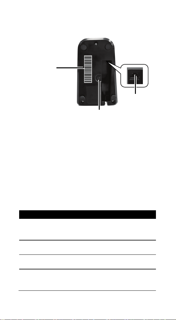
■ Bottom
Status
Scanner LED
Cradle LED
Flash blue at
intervals
Flash blue at
intervals
Scanner
Disconnected
Flash green
once
Flash green
once
Flash red every
timeout
Reset / Paging Button
Cradle Barcode
I/O Port
※ Long-time press Reset
※ Short-time press Paging
1.3 Indicators
1.3.1 Status lights
Status lights (LED) are helpful for checking
your scanner ’s status. Both your scanner and
cradle have LEDs, and each of them have four
colors: blue, green, red and amber. The table
below shows the LED behavior and the status
it indicates.
Scanner
Connected
Good Scan
Cradle ACK
Timeout
1-second
Off Off
0.5 second until
1-second
N/A
4
Page 13

Status
Scanner LED
Cradle LED
Firmware
Update
Flash green fast Flash green fast
Flash amber
slowly
Cradle
Charging
Flash amber,
slowly
Flash green
every second
Battery Full
Off
Solid green
Status
Scanner Sound
Cradle Sound
Scanner
Connected
Scanner
Disconnected
Good Scan
A short beep
N/A
Beeps five times
intervals
Cradle ACK
Timeout
Beeps once in
low tone
Three short
beeps (fast)
Memory Full
Sound 3
N/A
Two short
beeps
Interface
Ready
Power On
A long beep
A long beep
Reset
N/A
Sound 5
Cradle
Inquiry
Inquiry and
Charging Solid red
N/A
N/A
and green
green and red
1.3.2 Status sound
In addition to status lights, your scanner and
your cradle make sounds to indicate the status
it is in.
Sound 1 N/A
Sound 2 N/A
Cradle
Inquiry
N/A
at 1-second
A shor t beep
Battery Low
Programming
N/A
N/A
N/A Sound 4
5
Page 14

1.3.3 Vibration
Status
Scanner
Power On
Vibrate
Wake up from Sleep Mode
Vibrate
Good Scan
Vibrate
Your scanner vibrates in certain status.
6
Page 15

2 Get started
Charging by
Full Charge Time
Power Supply
4.5 hours
USB Cable
6.5 hours
This chapter provides information about how
to install, connect and use your scanner to do
your work, and how to charge and replace
your battery.
2.1 Installation
This section describes how to set up your
scanner.
2.1.1 Set up your scanner
1. Connect one end (RJ-45
connector) of the USB or
the RS-232 cable to your
cradle. Lay the cable into
the notch on the cradle
edge.
2. Connect the other end of the USB or the
RS-232 cable to your computer.
Note 1 If you’ve purchased the USB
pack, you can charge your scanner by
connecting the USB cable to your
computer.
Note 2 If you’ve purchased the RS-232
pack, connect the power supply to the
RS-232 cable and the wall outlet.
3. Place your scanner on your cradle to
4. Scan the Cradle code at the bottom of
charge it to full (cradle’s LED glows
green).
your cradle to establish the connection
between your scanner and cradle.
7
Page 16

5. To test your scanner, start a text
AR-3201 emits a light bar
processing program like Notepad or Word.
Scan a bar code and see if the data can be
sent to your computer. If it’s successful,
you’ll hear a beep and the bar code data
shows in the program.
2.1.2 How to scan
when it is scanning. This bar
needs to cross the bar code
horizontally to decode it.
2.1.3 Work with the ASCII table
Sometimes, you might need to send some
control characters that can’t be typed or enter
characters without a keyboard. You can do it
by using ASCII codes.
In Appendix B, you'll find the ASCII table.
Both column and row numbers are
hexadecimal. The ASCII code of a character is
the combination of a column and a row
number, where the column comes first. For
example, the ASCII code of BEL is "07" and
the number sign (#) is "23." You can use the
bar codes in Appendix D to scan ASCII codes.
2.1.4 Search your scanner
Sometimes you might leave your scanner
somewhere and can’t find it. In this case, press
and hold the RESET button at the bottom of
your cradle, until you receive a long beep
from your scanner, and you can locate it by
the beep sound.
8
Page 17

2.2 Battery
Charging by
Full Charge Time
Power Supply
4.5 hours
USB Cable
6.5 hours
Caution Keep the charging pins dry
screwdriver.
AR-3201 contains a lithium-ion battery that is
partially charged at the factory. You might
want to charge it to full before your use it. The
battery life varies depending on usage.
2.2.1 Charge the battery
You can charge the battery by connecting the
USB cable to your computer, or by using a
power supply (optional), which charges the
battery faster. When your scanner is fully
charged, your cradle’s LED turns to green.
when you put your scanner on your cradle
to charge the battery. Wet charging pins
may cause water seeping into your cradle
and shortening its life.
2.2.2 Replacing the battery
The battery’s life is consumed as you use and
charge it. You need to replace the battery
when it wears out. Please follow the steps
below to replace the battery.
1. Remove the rubber band around the scan
window of the scanner.
2. Remove the two fixing
screws on the lower
cover of the scanner by
using a Phillips
9
Page 18
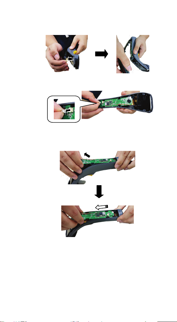
3. Please pull to remove the top cover of the
1
2
scanner directly by hand.
4. Please remove the battery cable from the
motherboard.
5. (1) Pull the motherboard up slightly and
then (2) pull out the scanner board in the
direction of the arrow.
10
Page 19

6. Take the old battery out. Next, install a
new battery.
7. Install the scanner's motherboard back and
insert the battery's cable into the projection
of the motherboard.
8. Please insert the connector of the battery
cable into the power jack of the
motherboard.
11
Page 20

9. Please install back the top cover of the
screwdriver.
the scanner.
scanner directly by hand.
10. Tighten the lower
cover of the scanner
with 2 screws by
using a Phillips
11. Install back the
rubber band around
the scan window of
12
Page 21

2.3 Connection
Your scanner can connect to three types of
devices: your cradle, a Bluetooth adapter or a
mobile device.
2.3.1 Connecting the Scanner with the
Cradle
Follow these instructions to link the two
devices:
1. Connect power to the cradle. The radio
LED (marked with a light symbol) will
blink amber and the cradle will beep.
2. To ensure the cradle is unlinked from any
other imager, check if the cradle sends an
inquiry beep or not (see Inquiry Beep
Control in page 24
3. Read the link label on the bottom of the
cradle with the imager. The imager will
sound a good read beep and the LED will
flash amber.
4. Re-place the imager in the cradle to
continue the charge.
Once a scanner is linked to a cradle, they will
remain linked until specific action is taken to
unlink them (see Unlinking). They will remain
linked if the cradle is unplugged, if the battery
is removed from the imager or if the entire
charge is used up, and if the imager is taken
out of range of the cradle. Under normal
operation, scanning of the link label will only
be required once in the life of the product.
th
).
13
Page 22

2.3.2 Disconnecting the Scanner from
the Cradle
There are three ways to unlink an imager from
a cradle:
Force imager to disconnect and sleep
1. Scan the “Force imager to disconnect
and sleep” barcode – Reading the unlink
barcode above while the imager is in range
of the cradle will break the link between
the two devices and allow another imager
to link to the cradle. It will also have the
imager in Deep Sleep Mode. If the
barcode is read when the imager is out of
range of its linked cradle, the imager will
unlink, but the cradle will remain linked to
the imager and will not allow another
imager to be linked to it. In this case, you
may perform the item 2 below to link
another imager.
2. Scan the Link Label and put on the
original cradle – If the cradle is linked
with an imager and the original pair was
stopped by out of range of the cradle or
out of battery of the imager, scan the link
label of the cradle with a new imager and
then put on the cradle, the cradle will drop
the original pair and establish a new link
with the new imager.
3. Scan the Link Label on an alternate
cradle – Scanning the link label on a
cradle will drop the link between the
original pair and establish a link between
the imager and new cradle. If the new link
is performed within range of the old cradle,
14
Page 23
it is free to establish a link to the next
imager that reads its link label. If it is done
outside of the range of the old cradle, it
retains its old link and will not allow a
new imager to link to it until a new imager
scan the link label and put on the cradle.
4. Push the “Reset” button on the bottom
of cradle – If the cradle is
linked with an imager and in
range, pushing the “Reset”
button (for about 2 seconds) on
the bottom of cradle will drop
the link between the devices. If
the button is pushed while the imager is
out of range, the cradle will unlink and
make itself available to other imagers. The
scanner will not drop its link with the
cradle automatically, but can be linked to
any other cradle by reading its link label.
* Note: If just push the button with a short time
(less than one second), a “Paging” feature will
be performed to page the imager which was
linked with the cradle.
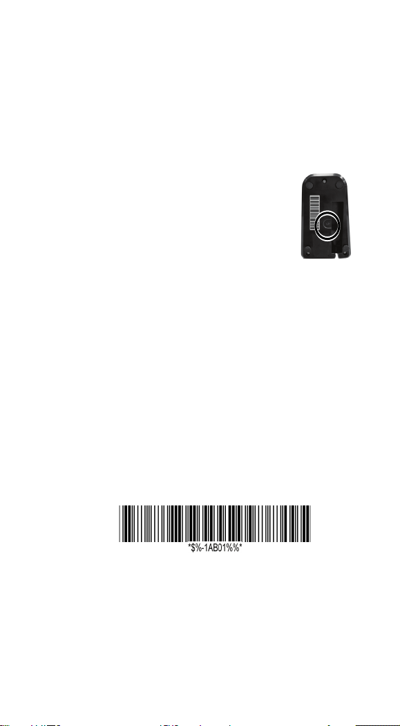
2.3.3 Connecting to your cradle again
If your scanner has connected to other device,
and you want it to connect to your cradle
again, do this:
1. Scan the following bar code.
2. Scan the bar code at the bottom of your
cradle.
2.3.4 Connecting to a Bluetooth adapter
If your computer has a Bluetooth adapter, you
can connect your scanner to your computer
without a cradle.
15
Page 24
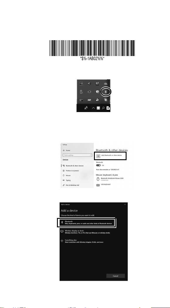
To connect your scanner to a Bluetooth
adapter:
1. Scan the PC/Android bar code.
2. Double click the Bluetooth icon in the
notification area.
Note Your c omputer needs to be
Bluetooth-enabled.
3. In the Bluetooth & other devices page,
tap Add Bluetooth or other device.
4. Tap Bluetooth.
16
Page 25
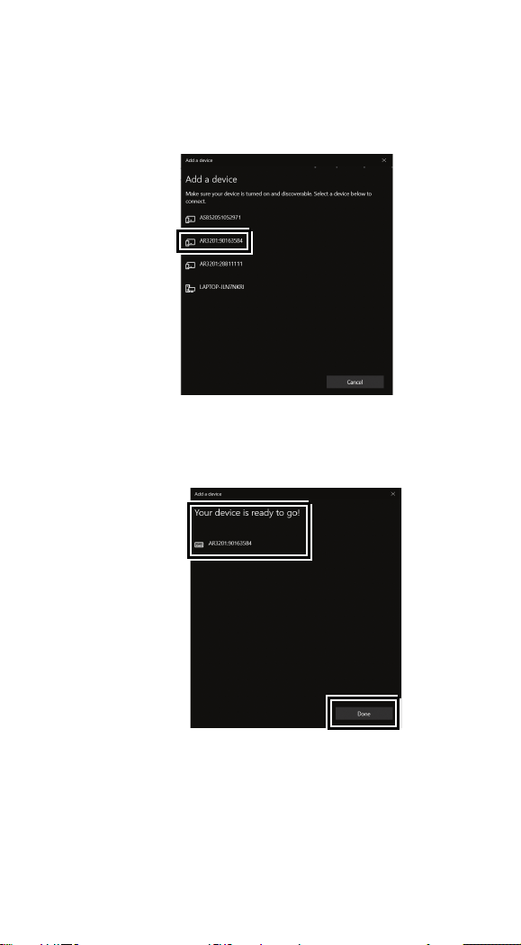
5. If it detects your scanner, it shows
“AR3201:XXXXXXXXX” (X is your
scanner’s serial number) in the list. Click
your scanner.
6. The computer will try to connect to your
scanner. If the connection is successful,
you’ll see the successful message. Click
Done.
17
Page 26
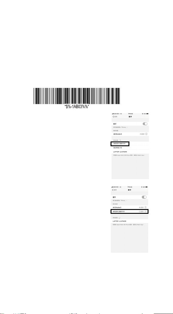
2.3.5 Connecting to a mobile device
2. On your iPhone, Go to
AR-3201 is able to connect to an iOS or Android
device that you can use to process bar codes.
Connecting to an iOS device
You can connect your scanner to an iOS device, such
as iPhone, iPad or iPod touch. The setup screen may
vary depending on your device. In this section, an
iPhone is taken for example.
1. Scan the “iOS HID” bar code.
Settings > Bluetooth. Turn on
Bluetooth, and your iPhone
searches other Bluetooth
devices automatically. If it
detects your scanner, it shows
“AR3201:XXXXXXXXX” (X
is your scanner’s serial
number) under DEVICES.
Tap your scanner to connect it.
3. When it connects successfully,
the status of your scanner is
changed to Connected.
18
Page 27
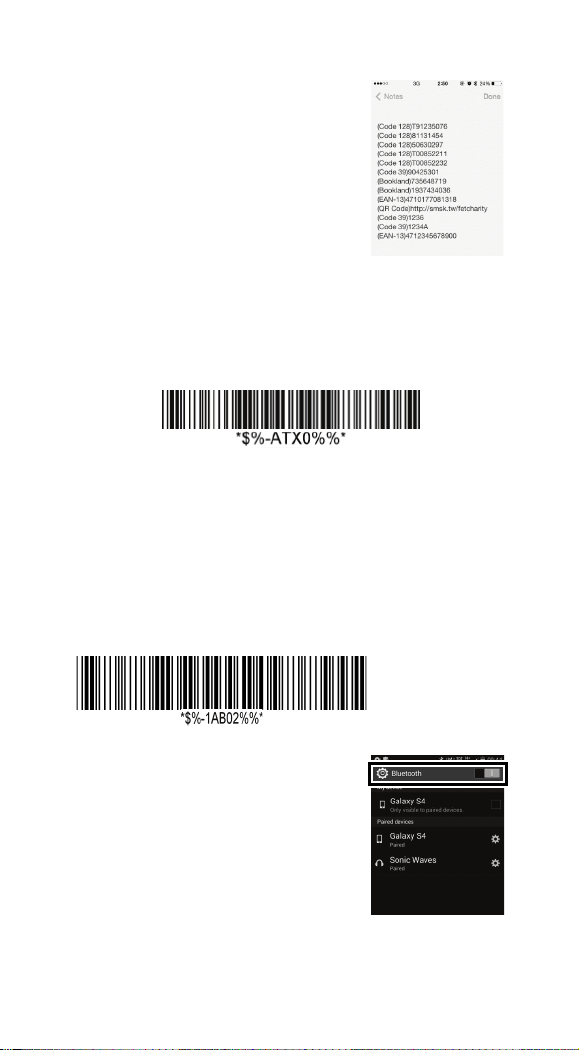
4. Tap Notes to open a new note.
Use your scanner to scan bar
codes and the data shows in
the note.
Note: Apple iOS devices will allow only one input device working
at the same time. So when you connect an Argox Cordless
Scanner with your Apple device, the Apple Virtual Keyboard will
be invalid automatically. To have the Apple Virtual Keyboard be
available again, you need to scan the barcode below.
Connecting to an Android device
You can connect your scanner to an Android device,
such as a smartphone or tablet. The setup screen may
vary depending on your device. In this section, we
use a smartphone as an example.
1. Scan the Android HID bar code.
2. On your Android smartphone,
go to the Bluetooth setting
screen. Turn on Bluetooth.
19
Page 28
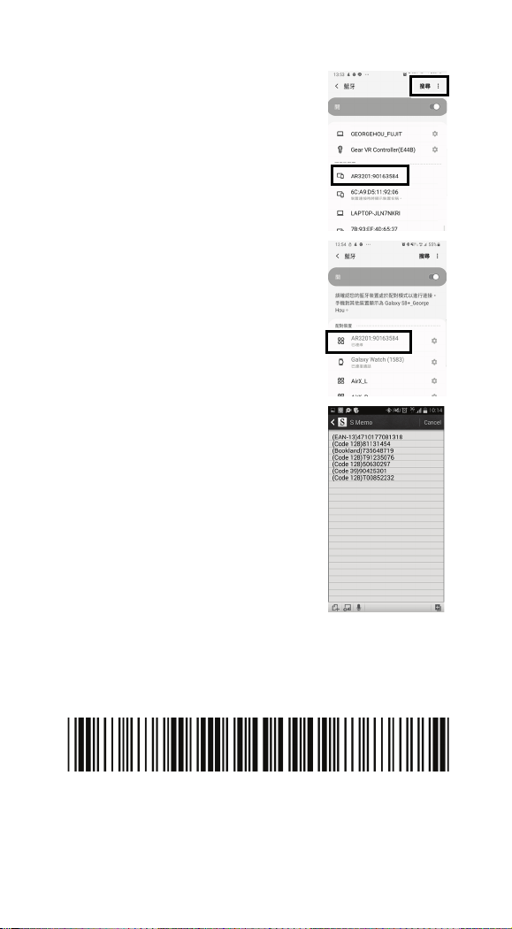
3. Tap Scan to search Bluetooth
devices. If it detects your
scanner, it shows
“AR3201:XXXXXXXXX” (X
is your scanner’s serial
number) in the list. Tap your
scanner to connect it.
4. When it connects successfully,
your scanner is shown under
Paired devices.
5. Tap a memo App to open a
new memo. Use your scanner
to scan bar codes and the data
shows in the memo.
2.3.6 Shipping Mode Setup
When the scanner enters shipping mode, the scanner
will be powered off. When being docked to cradle,
the scanner will back to power.
Shipping Mode Barcode
20
Page 29

3 Controls and settings
Important This function is work
Customize your scanner to work efficiently.
AR-3201 offers many features to match your
preferences. This chapter provides
information about how to change controls and
settings of your scanner.
User’s Default Setting
After setting your device, you can save your
setting as a User’s default. If you reset your
scanner to factory default, you can still load
your setting in this function.
Save your current setting as default
Restore your default setting
To customize your scanner, you need to scan a
series of programming bar codes in the correct
order. On the last page of this manual, you’ll
see a table of hexadecimal bar codes that can
be used with programming bar codes.
only when scanner is being connected to
cradle.
21
Page 30

To customize your scanner:
1. On the top of the setting table, scan the
Program bar code.
2. In the setting table, in the Setting column,
scan one of the bar codes.
3. On the last page, scan the bar codes that
correspond to the value you want in the Va l ue
column. When you finish, scan the Finish bar
code.
4. On the lower-right corner of the setting
table, scan the Exit bar code.
22
Page 31

Setting
Option
Value
RS-232
01
Exit
①
②
⑤
③
④
Scan Process
①Program ②Setting ③Value (using bar codes
on the last page)
Setting
④Finish ⑤Exit
Program
Program
Val ue (The last page)
Interface
selection
USB HID
RS-232/
USB HID
Auto
detection
USB Virtual
COM
03
04*
05
Finish
Exit
23
Page 32

3.1 Interface selection
Setting
Option
Val u e
RS-232
01
USB HID
03
USB Virtual
AR-3201 supports RS-232, USB HID and
virtual COM. By default, your scanner is able
to detect the interface automatically. When it
detects USB, it selects HID as your scanner’s
interface.
Program
RS-232/
Interface selection
USB HID
Auto detection
04*
(*) Default
24
COM
05
Exit
Page 33

3.1.1 USB HID key board
Keyboard layout
You can use it to change your keyboard layout,
so your scanner can scan bar codes of different
languages. Remember, you also need to change
your input method.
Function key
It maps function keys to ASCII codes, so you can
scan bar codes in place of the function key input.
For example, if you scan the numeric bar code “1”
and then “2,” your scanner sends the specific
character to your computer as though you press
F2. The code mapping range is from 01 to 1F.
For more information about ASCII codes, see
ASCII table in Appendix B.
Numeric key
The keypad is located to the rightmost of a
keyboard. You need to select this mode if your
program only accepts numerals. When selecting
Alt+Keypad, your bar code data will be sent as if
you’re pressing “Alt+number.” It is useful when
your bar code contains a special character, such
as the Euro sign (€).
Caps lock
It determines whether the state of the Caps Lock
key affects the output of bar codes.
Inter-character delay
It determines how fast your computer receives
each character and displays it on the screen. If
the speed is set too fast and your computer
system is slow, your computer may lose data.
25
Page 34

Block Delay
Setting
Option
Value
USA
00*
Function key
Disable
00
Alphabetic key
00*
It is a delay timer between barcode data output.
The feature is used to transfer continually with
shorter barcode data or multi-field scanning.
Keyboard layout
Program
Belgium
Denmark
France
Germany
Italy
Portugal
Spain
Sweden
Switzerland
UK
Latin American
Japanese
Enable
01
02
03
04
05
06
07
08
09
10
11
12
01*
Numeric key
Numeric keypad
Alt+Keypad
26
01
02
Page 35

Setting
Option
Value
Caps lock
Caps lock”ON”
00
Inter-character
delay
00 to 99.(ms)
00-99
delay
00-99 (10 ms)
00-99
Caps lock”OFF”
01*
02 *
Block transmission
(*) Default
10*
Exit
27
Page 36

3.1.2 RS-232
Flow control
• None
Your computer and scanner only use TxD
and RxD signals for communication. No
hardware or software flow control is used.
• RTS/CTS
It is hardware flow control. If your scanner
is ready to send bar code data to your
computer, it sends an RTS signal, and waits
to receive a CTS signal from your
computer. If your scanner doesn’t receive a
CTS after a timeout, you’ll hear five
warning beeps from it.
• Xon/Xoff
It is software flow control. When your
computer is unable to receive data, it sends
an Xoff signal to notify your scanner to
stop sending data; it sends an Xon signal
when it’s ready.
• ACK/NAK
Your scanner sends data after it received an
ACK signal from your computer, and will
resend data if it receives an NAK signal.
Inter-character delay
It determines how fast your computer receives
each character and displays it on the screen. If
the speed is set too fast and your computer
system is slow, your computer may lose data.
28
Page 37

Block Delay
Setting
Option
Value
None
00*
delay
00-99 (msec)
00-99
Block delay
00 to 99.
00 *
Response delay
00-99 (100 msec)
00-99
It is a delay timer between barcode data output.
The feature is used to transfer continually with
shorter barcode data or multi-field scanning.
Response delay
If you use RTS/CTS or ACK/NAK for flow
control, you can decide how long your scanner
waits your computer to acknowledge the data
transmission.
Program
Flow control
RTS/CTS
Xon/Xoff
01
02
Inter-character
*3AC*
(*) Default
ACK/NAK
03
00*
20*
Exit
29
Page 38

Exit
Setting
Option
Value
2400 bps
03
None
00*
Data bit
8 bits
00*
Stop bit
One bit
00*
Baud rate
4800 bps
9600 bps
Program
04
05
Parity
(*) Default
19200 bps
38400 bps
57600 bps
115200 bps
Odd
Even
7 bits
Two bits
06
07
08
09*
01
02
01
01
30
Page 39

3.2 Scan properties
■ Good-read off
After you pull the trigger, your scanner will keep
emitting the light bar, until it captures a good
scan or no bar code is decoded after the stand-by
duration elapsed.
■ Momentary
When you pull the trigger, the light bar is turned
on; when you release the trigger, the light bar is
turned off.
■ Alternate
The trigger acts as a toggle. When you pull the
trigger, the light bar is turned on; when you pull
it again, the light bar is turned off.
■ Timeout-off
When you pull the trigger, the light bar is turned
on. If no bar code is decoded after the stand-by
duration elapsed, the light bar is turned off.
■ Continue
It automatically detects and decodes bar codes in
your scanner ’s field of view. You can turn on this
mode when you want to decode bar codes
without pulling the trigger. If no bar code is
decoded after the stand-by duration elapsed, the
light bar will flash. You can move your scanner
or pull the trigger to wake it up.
■ Te s t only
It is reserved for engineers to test.
■ Auto-sensing
Similar to Continue, it automatically detects and
decodes bar codes in your scanner’s field of view.
If no bar code is decoded after the stand-by
duration elapsed, the light bar will be turned off.
31
Page 40

You can move your scanner or pull the trigger to
wake it up.
■ Double confirm
It determines how many times the decoder needs
to confirm a bar code.
■ Double read timeout
It determines the duration of Double confirm.
For example, if you set 5 times in Double
confirm and set 10 milliseconds in Double read
timeout, the decoder will decode a bar code 5
times in 10 milliseconds. You need to turn on
Double confirm to use this feature.
32
Page 41

Setting
Option
Value
Good-Read Off
00
duration
01-99 (second)
00-99
timeout
01-99 (100 msec)
01-99
00-09
00-09
Scan mode
Program
Momentary
Alternate
01*
02
Stand-by
Double read
Double confirm
(*) Default
Timeout Off
Continue
Test only
Auto-sensing
(00: no double
confirm)
03
04
05
06
06*
50*
00*
Exit
33
Page 42

■ Global min/max code length
The min and max code length defines the
decoding length of all bar codes. Note the
following when you set their length:
• If the length of a bar code is shorter than the
min or longer than the max, the bar code
won’t be decoded.
• If the min is equal to the max, the decoding
length is fixed.
• Some bar codes have their own decoding
length. If you set the individual min or max
decoding length for a bar code, your scanner
will go by the individual setting.
■ Inverted image scan
When you turn on this feature, you can scan both
regular and inverted bar codes.
■ Position indication
When you turn on this feature, the light bar keeps
flashing. This feature determines how long the
light bar flashes.
■ ISBT Concatenation time out
W
hen scanning single ISBT barcode, scanner will
wait 100ms, 200ms or 900ms to output barcode
single ISBT barcode because it has to seek
appended ISBT barcode until timeout.
■ Configuration Auto update
Every time your cradle connects to your scanner,
Auto Update automatically updates your
scanner’s configuration.
34
Page 43

Program
Setting
Option
Value
Global min. code length
00-99
00-99
Global max. code length
00-99
04-99
Inverted image scan
Disable
00*
Disable
00*
timeout
Disable
00
update
Disable
Position indication
*7AO*
ISBT Concatenation
Configuration Auto
Enable
30 seconds
60 seconds
90 seconds
120 seconds
150 seconds
180 seconds
Continue
100ms
200ms
900ms
Enable
4*
99*
01
01
02
03
04
05
06
07
01
02
09
00*
03
(*) Default
Exit
35
Page 44

3.3 Wireless Features
AR-3201 offers some operating modes that
help prevent data loss and extend battery life.
This section describes how to use these
modes.
■ Handcuff mode (Leash Alarm)
You can decide how long your scanner beeps
after it lost Bluetooth connection.
■ Data Collection mode
You can decide whether your scanner stores data
in its storage when it lost Bluetooth connection.
The storage size is 7 KB. If the storage is full,
you’ll hear an error beep when your scanner tries
to store data in it.
Note:
1. The scanner will preserve barcode when the
wireless is off, and will output data right after the
scanner is wirelessly connected to the cradle.
2. The scanner will preserve barcode when the
wireless is off, and will output data after the
scanner is wirelessly connected to the cradle and
its trigger key is pressed.
3. For the Force option, the scanner will preserve all
barcode until it is placed on the cradle.
■ Deep Sleep mode
To save battery power, you can put your scanner
into sleep if it doesn’t work in a certain amount
of time. To wake it up, just pull the trigger. Note
that your scanner needs 2-3 seconds to wake up,
since the engine needs a little time to start.
36
Page 45

Setting
Option
Value
Disable
00*
Disable
00
Disable
00*
Program
7AM
Handcuff Mode
(Leash Alarm)
7AN
Data Collection Mode
7AJ
Deep Sleep Mode
10 seconds
30 seconds
60 seconds
Enable1
Default
Force
10 minutes
30 minutes
60 minutes
(*) Default
10
30
60
01
2
3
02*
03
01
03
06
Exit
37
Page 46

3.4 Indicator
■ Power on alert
When your scanner is turned on, you’ll hear a
long beep.
■ Good read indication
The reaction after your scanner gets a good read.
■ Beeper indication
Your scanner will beep after it gets a good read.
■ Beep loudness
It is the volume of the good read beep. The
bigger the number, the higher the volume.
■ Beep tone freq.
It is the tone of the good read beep. The bigger
the number, the higher the tone.
■ Beep tone duration
It is the duration of the good read beep. The
bigger the number, the longer the duration.
■ Cradle Inquiry Beep
Adjust the cradle inquiry beep time.
■ Cradle Beep Loudness
Adjust the cradle Beep volume.
38
Page 47

Setting
Option
Value
Disable
00
Disable
00
Disable
00
00-07
00-07
00-99 (100 Hz)
00-99
00-99 (10 msec)
00-99
Disable
00*
Program
Power on alert
Good read indication
Beeper indication
Beep loudness
Beep tone freq.
Beep tone duration
Enable
Enable LED
Enable Vibration
Enable both
Enable
01*
01
02
03*
01*
07*
40*
10*
*5AJ*
Cradle Inquiry Beep
10 seconds
30 seconds
Continue
39
01
03
08
Page 48

*5AK*
Disable
00
Cradle Beep
Loudness
(*) Default
Volume 1
Volume 7
01
07
Exit
40
Page 49

3.5 Characters and strings
Length
Data
Setting
Option
Value
None
00*
None
0D*
(transmission)
3.5.1 Prefix and suffix
Prefix / Suffix characters setting
You can add a character at the beginning (prefix) or
at the end (suffix) of a bar code. You can use up to 22
ASCII characters to customize the prefix and suffix.
Code
Prefix Name Preamb le ID
Prefix characters
setting
1-22
characters
Barcode
Program
ID Posta mble Suffix
00-ffH
ASCII code
Suffix characters
setting
(*) Default
1-22
characters
00-ffH
ASCII code
Exit
41
Page 50

3.5.2 Preamble and postamble
Length
Data
■ Preamble / Postamble
In some cases, you may need additional
characters to identify your bar code data. A
preamble and postamble can help you to do
that. Remember, you need to turn on
preamble/postamble transmission to use it.
■ Preamble transmission
Add a preamble character or characters to a bar
code.
■ Postamble transmission
Add a postamble character or characters to a
bar code.
Code
Prefix Name Preamb le ID
Barcode
ID Posta mble Suffix
42
Page 51

Setting
Option
Value
Preamble
None
00*
None
00*
Disable
00*
Disable
00*
characters setting
Postamble
characters setting
Program
1-12characters
1-12haracters
00-ffH
ASCII
code
00-ffH
ASCII
code
Preamble
transmission
Postamble
transmission
(*) Default
Enable
Enable
43
01
01
Exit
Page 52

3.5.3 String groups
■ Insert G1/G2/G3/G4 character setting
You can insert up to two strings into a bar
code. Each string can contain up to 12
characters. First, you need to set a string
in a group, and then insert the group into
your bar code. There are four string
groups. You can decide which group you
want to use and where you want to insert
it. You can insert the same group two
times if you want.
Note if you want to insert G5-G10, use
Data Magic.
■ Insert data group position
It determines the position that the string
group will be inserted into. Note that the
insertion position can't exceed the length
of a bar code, or the group will be inserted
at the end of the bar code. The value “00”
inserts the group at the beginning of a bar
code, and “64” inserts the group at the
end of a bar code.
Example
To insert a string group into a bar code:
Step 1. Set a string in a group.
1. Scan the Program and Insert G1
characters setting bar codes.
2. In the ASCII code table, find the value of
the character you want to insert. For
example, if you want to insert the string
"AB," you'll find A→41, B→42.
44
Page 53

3. On the last page, scan "41" and "42," and
then scan the Finish bar code.
4. Scan the Exit bar code.
Step 2. Insert the string into the specified
position.
1. Scan the Program and Insert data group
1 position bar codes.
2. On the last page, scan “03,” and then scan
the Finish bar code. This means we’re
inserting the string into the third position
of a bar code.
3. Scan the Exit bar code.
Step 3. Specify the bar code you want to
insert.
1. We’re using Code 128 as an example. In
the section Code 128, scan the Program
and Insert group number selection bar
codes.
2. On the last page, scan “01,” and then scan
the Finish bar code. This means we’re
inserting Group1 into a Code 128 bar
code.
3. Scan the Exit bar code.
Original data: 258963
Result: 258AB963
45
Page 54

Setting
Option
Value
setting
None
00*
setting
None
00*
setting
None
00*
setting
None
00*
setting
None
00*
setting
None
00*
None
00*
Program
Insert G1 characters
Insert G2 characters
Insert G3 characters
Insert G4 characters
Insert G5 characters
Insert G6 characters
1-12
characters
1-12
characters
1-12
characters
1-12
characters
1-12
characters
1-12
characters
00-ffH
ASCII code
00-ffH
ASCII code
00-ffH
ASCII code
00-ffH
ASCII code
00-ffH
ASCII code
00-ffH
ASCII code
Insert G7 characters
setting
1-12
characters
46
00-ffH
ASCII code
Page 55

Setting
Option
Value
Insert G8 characters
setting
None
00*
setting
None
00*
setting
None
00*
position
00-63
00-63
position
00-63
00-63
position
00-63
00-63
position
00-63
00-63
1-12
characters
00-ffH
ASCII code
Insert G9 characters
Insert G10 characters
Insert data group 1
Insert data group 2
Insert data group 3
Insert data group 4
1-12
characters
1-12
characters
(00: no
insertion)
(00: no
insertion)
(00: no
insertion)
(00: no
insertion)
00-ffH
ASCII code
00-ffH
ASCII code
00*
00*
00*
00*
(*) Default
47
Exit
Page 56

3.5.4 ID, name and capitalization
■ Code ID position
You can choose to place Code ID before or
after a bar code.
Prefix Name Preamb le
ID Code
Length
■ Code ID transmission
Code ID is an identifier for a bar code. It
has two modes, Proprietary ID and AIM ID.
You can choose one of them. If you want
to customize the code ID using an ASCII
code, you need to choose Proprietary ID.
AIM ID is fixed since it is defined by the
AIM organization.
■ Code length transmission
It shows the length of a bar code at its
beginning. For example, if your bar code is
"258963," the result will be "06258963,” in
which 06 stands for the length of the bar
code.
■ Code name transmission
It shows the name of a bar code type at the
beginning of a bar code. For example, if
your bar code type is Code 39, and your
bar code is “09741258R,” the result is
“(Code-39)
09741258R.”
Barcode
Data
ID
Posta mble Suffix
■ Case conversion
You can change the capitalization of letters.
For example, if you choose Upper case, the
string “12aBcDeF” will be converted to
“12AB C D E F. ”
48
Page 57

Program
Setting
Option
Value
Before code data
00*
Disable
00*
Disable
00*
Disable
00*
Disable
00*
Code ID position
Code ID
transmission
Code length
transmission
Code name
transmission
Case conversion
(*) Default
After code data
Proprietary ID
AIM ID
Enable
Enable
Upper case
Lower case
(For bar code data
only)
01
01
02
01
01
01
02
Exit
49
Page 58

3.6 Scanner information
Setting
Bar code settings
Unique parameters
String settings
3.6.1 Parameters
It displays your scanner’s information on the
screen.
■ Bar code settings
It shows the current settings of all bar
codes.
■ Unique parameters
It shows the current values of the common
properties of all bar codes.
■ System parameters
It shows the current system settings of your
scanner, such as interface selection,
RS-232, indicator, transmission and the
scan mode.
■ String settings
It shows all settings of strings, such as
prefix, suffix, preamble, postamble and
string groups.
Program
System parameters
50
Exit
Page 59

3.6.2 Data Magic settings
Setting
Data Magic settings
Setting
Data Magic settings
It shows all settings of Data Magic.
Program
3.6.3 Firmware version
It shows the firmware version of your scanner.
Program
Exit
51
Page 60

3.7 Reset your scanner
By resetting your scanner, you can return your
scanner to the state it was in when you receive
it. This can help you solve some problems
caused by settings changed between scans.
Scan the following bar code to reset your
scanner and cradle:
There are two ways to reset your scanner.
■ Scan the bar code
Scan the following bar code to reset your
scanner.
■ Press and hold the RESET button
Press and hold the RESET button until you
hear the startup sound.
Remember the following when resetting your
scanner:
1. If your scanner is connected to your
cradle, when you scan the Reset scanner
bar code or press the RESET button, you
reset both of your scanner and cradle.
2. If your scanner is not connected to your
cradle, when you scan the Reset scanner
bar code, you only reset your scanner;
when you press the RESET button, you
only reset your cradle.
52
Page 61

Program
Setting
Note To meet the regulation of air
Reset scanner
Reset cradle
transportation, the wireless imager should
disconnect with the cradle during
shipment. All the cordless scanner are
suggested to scan the following command
before packaging into boxes and ship to
customers. This command will make the
scanner power off, and the scanner will be
powered on after being placed on the
charging cradle.
53
Page 62

3.8 Update firmware
Updating firmware improves functionalities
and performance for your scanner. If you want
to update the firmware of AR-3201, you need
to update your cradle’s firmware first. After
that, your cradle will reset and try to connect
to your scanner. Once they establish the
connection, your cradle will update your
scanner’s firmware.
USB connection
1. Start Scan Utility.
2. On the File menu, click New.
54
Page 63

3. In the NEW dialog box, select AR3201
or AR3201 from the Select Model list,
and click OK.
4. In the Scan Utility dialog box, click No.
5. On the Tool menu, click Download
Firmware > Download All (Scanner) or
Download All (Cradel).
55
Page 64

6. Scan Utility will ask if you want to
upgrade your scanner, click OK. In the
next dialog box, click OK. Then, you
need to wait 7 seconds for system to
switch your scanner to the DFU mode.
7. In the Change Firmware dialog box,
click Ask to get the current firmware
version of your scanner.
56
Page 65

8. Click Find to load the firmware file. The
firmware version in this file needs to be
different from the current firmware
version of your scanner. After loading the
file, click Download to update the
firmware.
9. After the update is completed, click OK.
57
Page 66

RS-232 connection
1. Start Scan Utility.
2. On the File menu, click New.
3. In the NEW dialog box, select AR3201
or AR3201 from the Select Model list,
and click OK.
4. In the Scan Utility dialog box, click No.
58
Page 67

5. On the Tool menu, click Host RS-232
Setup.
6. In the Host RS-232 Setup dialog box,
select the COM port your scanner is using
and click Port Setting.
7. In the Port Setting dialog box, in the
Baud rate list, select 115200 and click
OK.
59
Page 68

8. In the Host RS-232 Setup dialog box,
click OK.
9. On the Tool menu, click Download
Firmware > Download All (Scanner).
10. In the Change Firmware dialog box,
click Ask to get the current firmware
version of your scanner.
60
Page 69

11. Click Find to load the firmware file. The
firmware version in this file needs to be
different from the current firmware
version of your scanner. After loading the
file, click Download to update the
firmware.
12. After the update is completed, click OK.
61
Page 70

3.9 Data Magic
Important Data Magic default is
Data Magic offers 10 commands for you to
customize text strings of bar codes. Each
command can be specified in a rule. Data
Magic allows up to 10 rules to be applied.
With the flexibility Data Magic provides, you
can define data as you want.
There are two ways to use Data Magic:
scanning bar codes, or using Scan Utility. By
scanning bar codes, you can quickly change
the settings without using programs; by using
Scan Utility, you can see the settings at a
glance and change them through the
easy-operated user interface. Choose the
method that meets your need.
disabled. To enable Data Magic function,
go to chapter 4
Magic column to enable it.
Bar codes and find Data
62
Page 71

Data Magic commands
InsertF
Definition
Attributes
InsertB
Definition
Attributes
CutF
Definition
Attributes
CutB
Definition
Attributes
KeepF
Definition
Attributes
Insert a
character or
characters from
the left
of a text
string.
Insert a
character or
characters from
the right
text string.
Remove a
character or
characters from
the left
string.
Remove a
character or
characters from
the right
text string.
of a
of a text
of a
■ Position: The position you
want to insert the character.
■ String: The specified group.
■ Position: The position you
want to insert the character.
■ String: The specified group.
■ From: The starting position
of the text to be removed.
■ To: The end position of the
text to be removed.
■ From: The starting position
of the text to be removed.
■ To: The end position of the
text to be removed.
Retain a
character or
■ From: The starting position
of the text to be retained.
63
Page 72

characters from
the left of a text
KeepB
Definition
Attributes
FindF
Definition
Attributes
FindB
Definition
Attributes
Replace
Definition
Attributes
string.
■ To: The end position of the
text to be retained.
Retain a
character or
characters from
the right
text string.
Remove a
certain length
of the string
from the left
Remove a
certain length
of the string
from the right
of a
.
.
■ From: The starting position
of the text to be retained.
■ To: The end position of the
text to be retained.
■ String: The specified group.
■ Include: Remove everything
before the specified string.
■ Exclude: Remove the
specified string and
everything before it.
■ String: The specified group.
■ Include: Remove everything
before the specified string.
■ Exclude: Remove the
specified string and
everything before it.
Replace the text
in the original
text string with
a different text
■ String: The text in the
original text string.
■ With String: The string that
64
Page 73

string.
replaces the specific text.
Erase
Definition
Remove the
Attributes
specified rule.
Position Range: 0-99
Cut Range: From: 1-99, To: 1-99
Note If you use Data Magic by scanning
bar codes, you don’t need the Erase
command.
None.
65
Page 74

3.9.1 Bar code scanning
Item
Description
The rule number. The lower
The command you specify in
The attribute varies according
The attribute varies according
Command
Attribute 1
Attribute 2
InsertF
Position
String
InsertB
Position
String
CutF
From
To
CutB
From
To
KeepF
From
To
KeepB
From
To
FindF
String
Include or
Bar code scanning is a quick way to work
with Data Magic. Just scan the bar codes in
specific order, and you can customize your
string in seconds.
Data format
Data Magic provides 10 rules for you to set.
To set a rule, follow this data format to scan
bar codes:
Program + Rule + Command + Attribute 1
+ Attribute 2 + Finish + Exit
the number, the higher the
Rule
priority. The rule with the
high priority will be applied
first.
Command
Attribute 1
Attribute 2
the rule.
to the command.
to the command.
Exclude
66
Page 75

Item
Description
FindB
String
Include or
Exclude
Replace
String
With String
Erase - -
67
Page 76

To set an InsertF rule with the sample data, scan the
following bar codes:
Program
RULE1
InsertF
Attr1 (Two digits)
Attr2 (Two digits)
Finish
Exit
68
Page 77

Bar codes
Data Magic Rules
RULE
RULE
RULE
RULE
RULE
RULE
RULE
RULE
RULE
RULE
Data Magic Commands
The bar codes below are Data Magic rules.
They consist of two digits. The first digit “9”
indicates Data Magic; the second indicates the
rule number.
1
3
5
7
9
The bar codes below are Data Magic commands.
0→InsertF
2
4
6
8
10
1→CutF
2→CutB
3→Replace
69
Page 78

4→KeepF
Program
Rul
Attribute
Attribute
1
InsertF
0 5 0
4
5→KeepB
6→FindF
8→InsertB
Example
Original Text String: ARGOX89121121
Group 1: ARGOX Group 2: argox
Group 3: GOX Group 4: Tel:
InsertF
Insert Group 4 (Attr 2) into the fifth (Attr 1)
position from the left side of the string.
Command
e
Data: ARGOX89121121
Result: ARGOXTel:89121121
1
7→FindB
9→Erase
2
Finis
h
Exit
70
Page 79

InsertB
Program
Rul
Attribute
Attribute
2
InsertB
0 8 0
4
Program
Rul
Attribute
Attribute
3
CutF
0 1 0
5
Program
Rul
Attribute
Attribute
4
CutB
0 1 0
8
Insert Group 4 (Attr 2) into the eighth (Attr 1)
position from the right of the string.
e
CutF
e
CutB
Command
Data: ARGOX89121121
Result: ARGOXTel:89121121
Remove first 5 characters from the left of the
string.
Command
Data: ARGOX89121121
Result: 89121121
Remove first 8 characters from the right of the
string.
1
1
2
2
Finis
h
Finis
h
Exit
Exit
e
Command
Data: ARGOX89121121
Result: ARGOX
1
71
2
Finis
h
Exit
Page 80

Replace
Program
Rul
Attribute
Attribute
5
Replace
0 1 0
4
Program
Rul
Attribute
Attribute
6
KeepF
0 3 0
8
Program
Rul
Attribute
Attribute
7
KeepB
0 3 0
8
In the original string, replace the Group 1
(Attr1) with Group 4 (Attr2).
e
KeepF
e
KeepB
e
Command
Data: ARGOX89121121
Result: Tel:89121121
Keep the characters from (Attr1) to (Attr2)
from the left of the string.
Command
Data: ARGOX89121121
Result: GOX891
Retain the characters from (Attr1) to (Attr2)
from the right of the string.
Command
1
1
1
2
2
2
Finis
Finis
Finis
Exit
h
Exit
h
Exit
h
Data: ARGOX89121121
Result: 891211
72
Page 81

FindF
Program
Rul
Attribute
Attribute
8
FindF
0 3 0
1
Program
Rul
Attribute
Attribute
9
FindB
0 3 0
1
Rule
Command
Rule 10
Erase
Remove Group 3 (Attr 1) and everything
before it from the left of the string. Attribute 2
can be “00” or “01.”
Command
e
00: Include 01: Exclude
Data: ARGOX89121121 Data:
ARGOX
Result: GOX89121121 Result: 89121121
FindB
e
00: Include 01: Exclude
Data: ARGOX89121121 Data:
ARGOX89121121
Result: ARGOX Result: AR
89121121
Remove Group 3 (Attr 1) and everything
before it from the right of the string. Attribute
2 can be “00” or “01.”
Command
1
1
2
2
Erase
Remove the specified rule.
Finis
h
Finis
h
Exit
Exit
Program
Exit
73
Page 82

Erase
OR
To r emo ve all values in Data Magic, scan the
bar code below.
Display the current settings
To display the current settings of Data Magic,
scan the following bar codes:
Program
Display Data Magic
settings
Displays Inserted
Group settings
74
Page 83

Scan Utility
Scan Utility provides a simple, clear interface
that you can easily view and change Data
Magic settings, and import or export the
settings to your scanner. Currently, Scan
Utility uses RS-232 for data transmission. If
your scanner is connected via a USB port, you
need to install Virtual COM for Scan Utility to
transmit data. For more information about
installing Virtual COM, see Virtual COM.
To use Data Magic, start Scan Utility and do
this:
1. On the File menu, click New.
2. In the NEW dialog box, select AR3201
or AR3201 from the Select Model list,
and click OK.
3. In the Scan Utility dialog box, click No.
4. On the Setup menu, Click Linear
Barcode setup. Select which code you
want to use then enable Data matrix
function, click OK.
5. On the Setup menu, click Scanner Setup,
and click the Data Magic tab.
6. In the Data Magic tab, select the Data
Magic check box.
7. Click one of the rules you want to set. For
example, if you want to set Rule 1, select
its Enable check box. In the command
list, click the command you want, such as
InsertF. In the position box, type a
position number. In the string list, click
the group you want.
75
Page 84

8. Repeat the previous step until you set all
the rules you need, and click the String
tab.
9. In the String tab, there are 10 string
boxes: Insert G1-G10 chars setting.
Each box corresponds to the group
you’ve selected in the string list in the
Data Magic tab. Depending on your
selection, type the text you want in the
specific box. For example, if you’ve
selected Group1, type in the Insert G1
chars setting box. The string box accepts
up to 12 single-byte characters. When
you’re done, click OK.
10. On the Tool menu, click Export Config
(from Host), and click Export. If the
data is exported successfully, you’ll hear
a long beep.
In the Data Magic tab, you’ll find 10 rules.
Each rule can be set to one of the commands.
The table below describes how to use those
commands.
76
Page 85

Command
Example
InsertF
Position: 1
Result: 1Argox2345678
InsertB
Position: 1
Result: 1234567Argox8
CutF
From: 2 To: 4
Result: 15678
CutB
From: 2 To: 4
Result: 12348
Replace
String: Group1
Result: 123Argox78
KeepF
From: 2 To: 4
Result: 234
KeepB
From: 2 To: 4
Result: 567
FindF
String: Group 3
■ Result: 678
String: Group 2
Group 2: Argox
Original String: 12345678
String: Group 2
Group 2: Argox
Original String: 12345678
Original String: 12345678
Original String: 12345678
With String: Group 2
Group 1: 456
Group 2: Argox
Original String: 12345678
■
Original String: 12345678
Original String: 12345678
Group 3: 45
Original String: 12345678
Include/Exclu: Include
Result: 45678
Include/Exclu: Exclude
77
Page 86

Command
Example
FindB
String: Group 3
Group 4: 45
■ Result: 123
Erase
In Rule 10, In the command list, click
box to remove the rule.
Original String: 12345678
Include/Exclu: Include
Result: 12345
■
Include/Exclu: Exclude
Erase, and Rule 10 will be removed.
You can also clear the Enable check
78
Page 87

Virtual COM
You can configure Virtual COM to transmit
data to a computer via a virtual COM port.
After installing Virtual COM, your scanner
will be assigned a virtual COM port, which
you can use to receive or send data.
To configure Virtual COM on Windows XP
and set up a virtual COM port in Scan Utility:
1. Connect your scanner to your computer.
2. Use the bar code in Interface Selection to
switch the interface to Virtual COM. If
the interface is set successful, you’ll hear
a long beep, and Found New Hardware
Wizard will appear on screen.
3. In the Found New Hardware Wizard
dialog box, click Install from a list or
specific location (Advanced), and click
Next.
4. Click Search for the best driver in these
locations, and select the Include this
location in the search check box. Next,
click Browse, and find the driver at your
installation path of Scan Utility (default is
C:\Program Files\Argox\Scan
Utility\driver\virtual com), and then click
Next.
5. After the driver installed, click Finish.
6. Right-click My Computer and click
Properties.
7. Click the Hardware tab, and click
Device Manager.
79
Page 88

8. Click Ports (COM & LPT). Find
ARGOX Virtual COM and see the port
number in the parenthesis.
9. Close Device Manager.
10. Start Scan Utility. On the File menu, click
New. In the Select Model list, click
AR3201 or AR3201, and click OK.
11. On the Tool menu, click Host RS-232
Setup.
12. In the Host RS-232 Setup dialog box, in
the RS-232 Setting list, click the port
you’ve seen in step 8, and click Port
Setting.
13. In the Port Setting dialog box, in the
Baud rate list, click 115200, and click
OK.
Note The installation steps may vary
depending on your operating system.
80
Page 89

4 Bar codes
Leading
Data Digits
Check
Each bar code has different attributes for you
to change as you need.
UPC-A
Format
Zero
■ Read Turn on or turn off the read function.
■ Checksum transmission Append the check
digit to the end of a bar code.
■ Data Magic Turn on or turn off Data Magic.
■ Truncate leading/ending You can truncate
characters from the left (Truncate leading) or the
right (Truncate ending) of a bar code. Your
scanner beeps if the truncate length is longer than
the bar code, or the parts being truncated by
Truncate leading and Truncate ending are
overlapped. You can truncate up to 15 characters.
■ Code ID setting Code ID is an identifier for a
bar code. It has two modes: Proprietary ID or
AIM ID. If you want to customize the code ID
using an ASCII code, you need to choose
Proprietary ID. You must turn on Code ID
transmission to use Code ID. For further details,
see Section 3.4.4,
(11 Digits)
ID, name and capitalization.
Digit
81
Page 90

Program
Setting
Option
Value
Read
Disable
00
Checksum transmission
Disable
00
Data Magic
Disable
00*
Truncate leading
0-15
00-15
Truncate ending
0-15
00-15
00-ffH
00-ffH
Code ID setting
■ Insertion group number selection
It allows you to insert up to two strings into a bar
code. First, you need to set a string in a group,
and then insert the group into your bar code.
There are four string groups. You can insert the
same group two times if you want. For more
information about how to set a string in a group,
see Section 3.4.3,
Enable
Enable
Enable
ASCII
01*
01*
01
00*
00*
< A >*
code
Exit
String groups.
82
Page 91

Example:
Supplement digits
Setting
Option
Value
number selection
00-44
number: 0-4)
00-44
None
00*
To insert Group 2, set the value as 02 or 20.
To insert Group 1 and 4, set the value as 14 or
41.
To insert Group 3 two times, set the value as 33.
Note Zero (0) means no group is inserted.
■ Supplement digits If your bar code has a
supplemental bar code, you can use this feature
to decode it. The supplemental bar code can be 2
or 5 digits.
Leading
Zero
Insert group
Supplement
digits
Data Digits
(11 Digits)
Check
Digit
Program
(The range of
the single-digit
2 digits
5 digits
2,5 digits
UCC/EAN 128
2, UCC/EAN
128
5, UCC/EAN
128
All
83
2 or 5 or
UCC / EAN 128
00*
01
02
03
04
05
06
07
Exit
Page 92

■ Truncation/Expansion
Setting
Option
Value
None
00
00-99
00-99
• Truncate It truncates the leading zeros of a
UPC-A bar code.
• Expansion It converts a UPC-A bar code
to the EAN-13 format.
■ Supplement check counter The decoder needs
to capture the supplemental bar code within the
number of times the check counter specified, or
it determines there’s no supplement. If you
setting 00, it will be failed when you read
supplemental bar code.
Program
Truncate leading
01*
Truncation/
Expansion
zero
Expand to EAN13
02
Supplement
check counter
The
(verification)
84
5*
Exit
Page 93

UPC-E
Leading
Data Digits
Format
Zero
■ Read Turn on or turn off the read function.
■ Checksum transmission Append the check
digit to the end of a bar code.
■ Data Magic Turn on or turn off Data Magic.
■ Truncate leading/ending See the description
in UPC-A.
■ Code ID setting See the description in UPC-A.
(6 Digits)
Check Digits
85
Page 94

Setting
Option
Value
Read
Disable
00
transmission
Disable
00
Data Magic
Disable
00*
Truncate leading
0-15
00-15
Truncate ending
0-15
00-15
Code ID setting
00-ffH ASCII
00-ffH
Program
Enable
01*
Checksum
■ Insertion group number selection See the
description in UPC-A.
■ Supplement digits See the description in
UPC-A.
Enable
Enable
code
86
01*
01
00*
00*
< E >*
Exit
Page 95

Format
Data
Supplement digits
Leading
Zero
■ Truncate/Expansion
• Truncate It truncates the leading zeros of a
• Expansion It converts a UPC-E bar code
■ Expansion It extends a UPC-E bar code to
13-digit.
■ UPC-E1 It allows your scanner to decode
UPC-E bar codes that begin with the number one
(1).
■ Supplement check counter See the
description in UPC-A.
Digits
(6 Digits)
UPC-E bar code.
to the EAN-13 or UPC-A fo r mat.
Check
2 or 5 or
Digit
UCC / EAN 128
87
Page 96

Program
Setting
Option
Value
00-44
00-44
None
00*
None
00*
Expansion
Disable
00*
UPCE-1
Disable
00*
00-99
00-99
Insert group
number selection
Supplement digits
Truncation/Expansi
on
2 digits
5 digits
2,5 digits
UCC/EAN 128
2, UCC/EAN 128
5, UCC/EAN 128
All
Truncate leading
zero
Expand to
EAN13
Expand to UPCA
Enable
Enable
00*
01
02
03
04
05
06
07
01
02
03
01
01
Supplement check
counter
(verification)
88
05*
Exit
Page 97

EAN-13
Data Digits (12 Digits)
Check Digits
Setting
Option
Value
Read
Disable
00
Disable
00
Data Magic
Disable
00*
Truncate leading
0-15
00-15
Truncate ending
0-15
00-15
Format
■ Read Turn on or turn off the read function.
■ Checksum transmission Append the check
digit to the end of a bar code.
■ Data Magic Turn on or turn off Data Magic.
■ Truncate leading/ending See the description
in UPC-A.
Program
Enable
01*
Checksum
transmission
Enable
Enable
89
01*
01
00*
00*
Exit
Page 98

■ Code ID setting See the description in UPC-A.
Supplement Digits
■ Insertion group number selection See the
description in UPC-A.
■ Supplement digits See the description in
UPC-A.
Format
Data Digits
(12 Digits)
■ ISBN/ISSN conversion The ISBN
(International Standard Book Number) and ISSN
(International Standard Serial Number) are bar
codes for books and magazines, respectively. The
old ISBN is 10-digit and the old ISSN is 8-digit.
When you turn on this feature, it converts the
new ISBN and ISSN to their old format.
■ ISBN ID Setting You can set ISBN ID with
ASC II code.
■ Supplement check counter See the
description in UPC-A.
Check
Digits
2 or 5 or
UCC / EAN 128
90
Page 99

Program
Setting
Option
Value
Code ID setting
00-ffH ASCII
00-ffH
00-44
00-44
None
00*
Disable
00*
ISBN ID setting
00-ffH ASCII
00-ffH
00-99
00-99
Insert group
number selection
Supplement digits
ISBN/ISSN
conversion
Supplement check
counter
code
2 digits
5 digits
2,5 digits
UCC/EAN 128
2, UCC/EAN
128
5, UCC/EAN
128
All
Enable
code
(verification)
< F >*
00*
01
02
03
04
05
06
07
01
< l>*
05*
Exit
91
Page 100

EAN-8
Data Digits (7 Digits)
Check Digits
Format
■ Read Turn on or turn off the read function.
■ Checksum transmission Append the check
digit to the end of a bar code.
■ Data Magic Turn on or turn off Data Magic.
■ Truncate leading/ending See the description
in UPC-A.
■ Code ID setting See the description in UPC-A.
■ Insertion group number selection See the
description in UPC-A.
92
 Loading...