

Page 1
Assembly Instructions - Please keep for future reference
Issue 2 - 12/12/13
MADE IN
BRITAIN
If you need help or have damaged or missing parts, call the Customer Helpline: 0870 112 1928
or email: Help@ClickSpares.co.uk (quoting your original order number)
Important - Please read these instructions fully before starting assembly
Dimensions
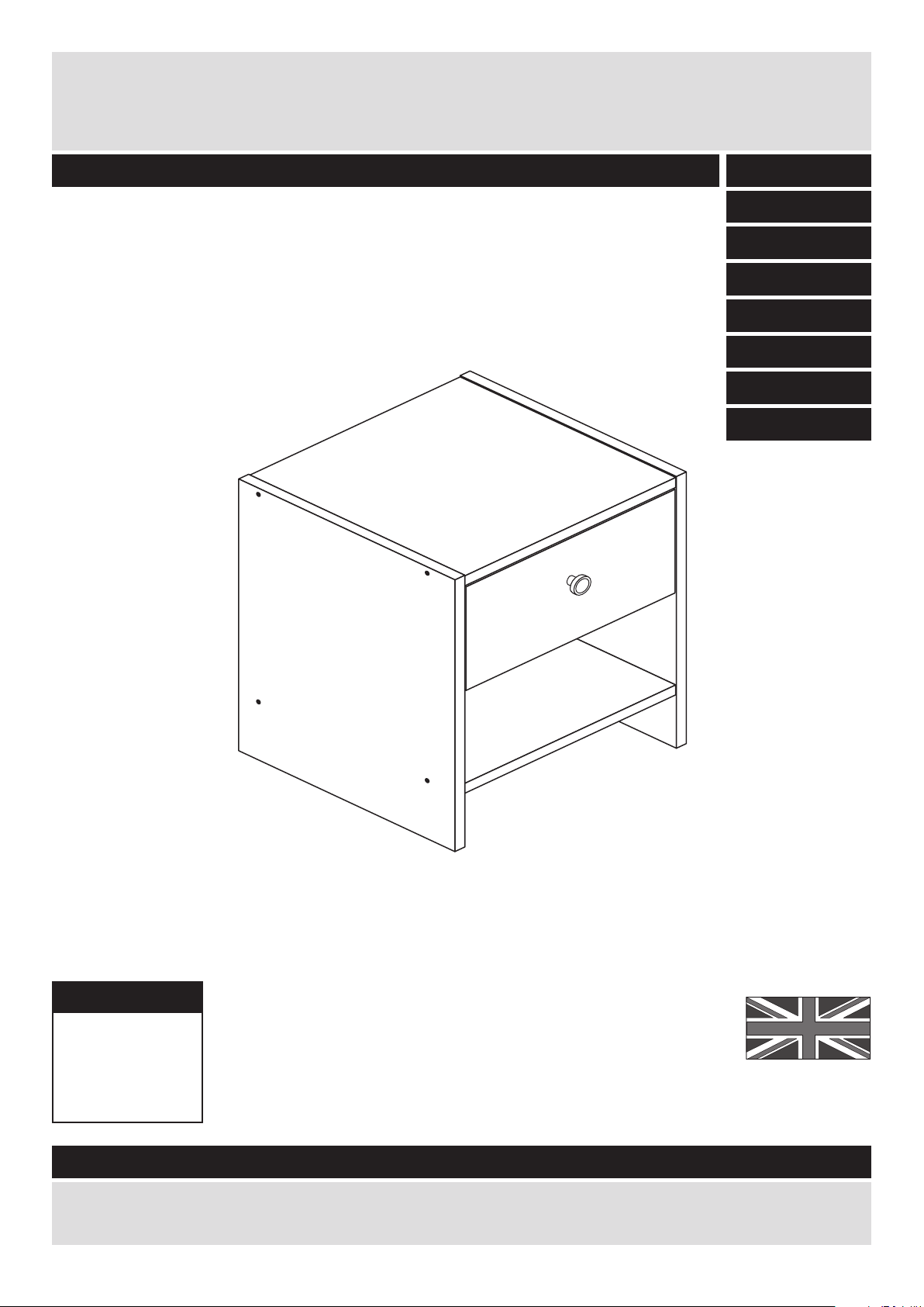
Seville - Bedside
171/8140
145/0446
157/3622
170/9214
Width - 35.5cm
Depth - 33cm
Height - 41.5cm
160/9785
162/9325
162/7956
159/7732
Page 2

Safety and Care Advice
Important - Please read these instructions fully before starting assembly
• Warning: This unit weighs
approximately 7kgs.
Please lift with care.
• Check you have all the
components and tools listed on
pages 2 and 3.
• Remove all fittings from the
plastic bags and separate them
into their groups.
• Keep children and animals
away from the work area, small
parts could choke if swallowed.
• Parts of the assembly will be
easier with 2 people.
• Make sure you have enough
space to layout the parts before
starting.
• Do not stand or put weight on
the product, this could cause
damage.
• Assemble the item as close to
its final position (in the same
room) as possible.
• Assemble on a soft level
surface to avoid damaging the
unit or your floor (use opened
out unit carton).
• We do not
recommend the
use of power
drill/drivers for
inserting screws,
as this could damage the unit.
Only use hand screwdrivers.
• Safety note: If there is any
chance of this unit being pulled
over by children etc. it is
recommended that the unit is
secured to a wall using suitable
fixings (not supplied).
• Dispose of all packaging
carefully and responsibly.
1
Care and maintenance
• Only clean using a damp cloth
and mild detergent, do no use
bleach or abrasive cleaners.
• From time to time check that
there are no loose screws on
this unit.
• This product should not be
discarded with household
waste. Take to your local
authority waste disposal centre.
Note: If required the next page
can be cut out and used as
reference throughout the
assembly. Keep this page with
these instructions for future
reference.
Page 3
2
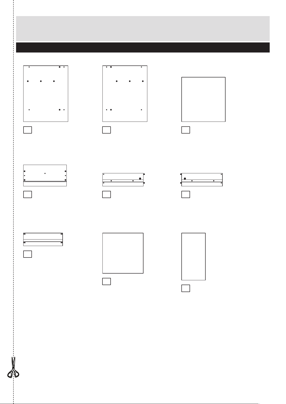
Components - Panels
Please check you have all the panels listed below
If you have damaged or missing components, call the
Customer Helpline: 0870 112 1928 or email:
Help@ClickSpares.co.uk (quoting your original order number
and the reference numbers below)
1
2 3
Top/Base (D2493A)
(321 x 327mm) x 2
Left Side (D2494A)
(412 x 328mm)
Right Side (D2495A)
(412 x 328mm)
Drawer Front (D2496A)
(317 x 157mm)
Left Drawer Side (W410LH)
(300 x 95mm)
Right Drawer Side (W410RH)
(300 x 95mm)
Drawer Back (W288-95)
(288 x 95mm)
Drawer Base (T299-297)
(299 x 297mm)
Back (X175-347)
(175 x 347mm)
4 5 6
7
8
9
Page 4
3
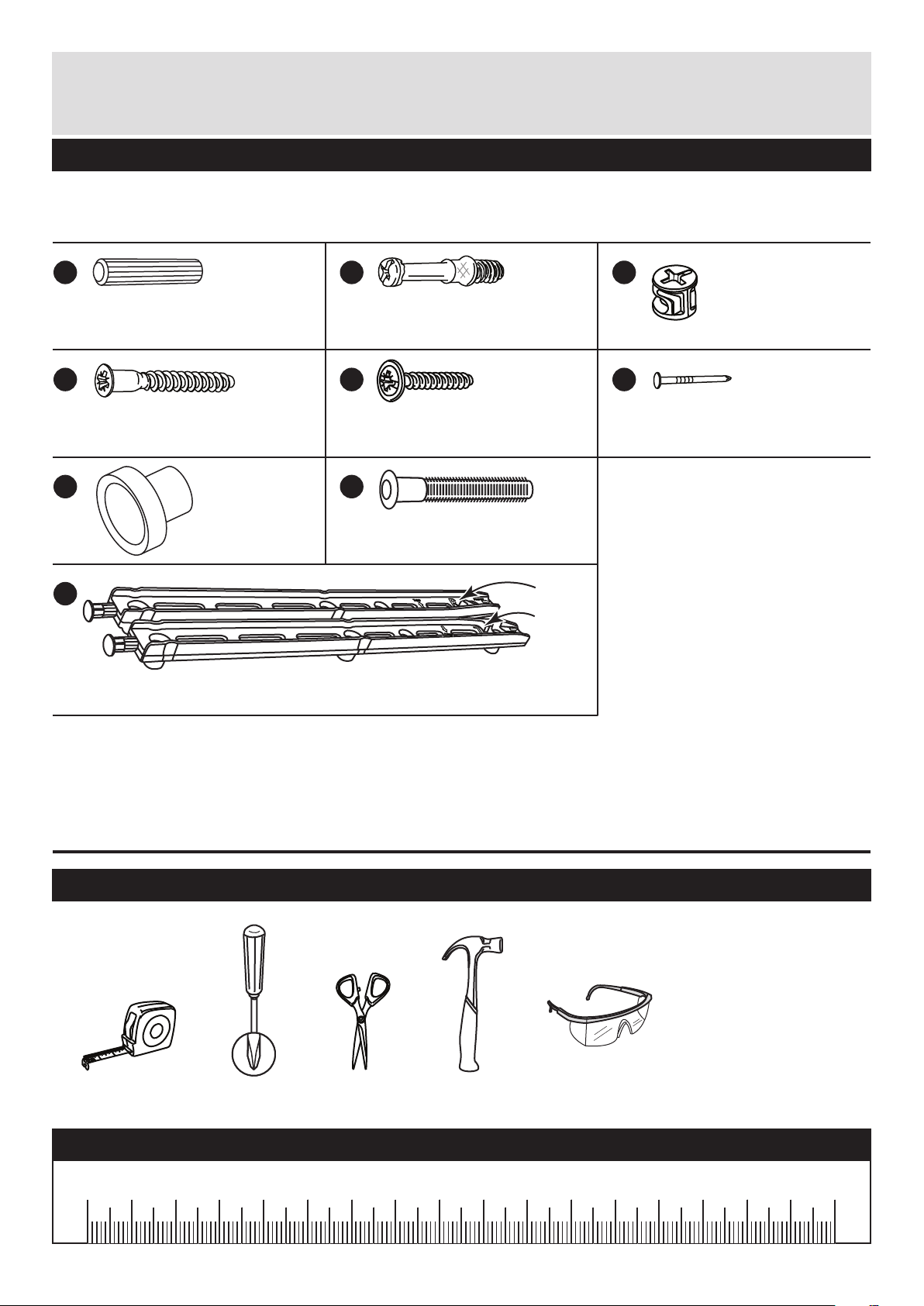
mm 10 20 30 40 50 60 70 80 90 100 110 120 130 140 150 160 170mm 10 20 30 40 50 60 70 80 90 100 110 120 130 140 150 160 170
Ruler - Use this ruler to help correctly identify the screws
Please check you have all the fittings listed below
Note: The quantities below are the correct amount to complete the assembly. In some cases
more fittings may be supplied than are required.
Components - Fittings
If you have damaged or missing components, call the
Customer Helpline: 0870 112 1928 or email:
Help@ClickSpares.co.uk (quoting your original order number
and the reference numbers below)
Tools required
Rule Scissors Hammer
Eye protection
(when using a
hammer or drill)
Cross-head
screwdriver
A
Wooden dowel (F22) x 4
B
Metal dowel (F901) x 2
C
D E F
G
Small locking
nut (F3) x 2
Nail (F51) x 540mm Screw (F910) x 8
Handle (F300) x 1
H
Knock-in Peg (F171WH) x 4
I
R (F601)
L (F600)
F599
F599
Drawer stops (F599) x 2
Runners (F600) x 1 and (F601) x 1
25mm Screw (F95) x 1
Page 5

4
Step 1
Assembly Instructions
If you have damaged or missing components, call the
Customer Helpline: 0870 112 1928 or email:
Help@ClickSpares.co.uk (quoting your original order number
and the reference numbers below)
B
C
Prepare the drawer
front
Screw 2 metal dowels
into the holes shown on
the back of the drawer
front .
Note: Tighten metal
dowels up fully against
the panels.
B
4
Prepare the drawer
sides
Insert a small locking
nut into the hole
shown on the left drawer
side and right drawer
side .
Note: Arrow on locking
nut must point towards
hole in edge of panel.
C
5
6
Step 2
C
5
C
6
B
B
4
Step 3
Attach the drawer
sides to the drawer
front
Push the left drawer side
. and right drawer side
. onto the back of the
drawer front .
Turn the small locking
nuts on the left
drawer side and right
drawer side .
Note: Turn the locking
nuts clockwise to
secure panels - more
than 1/2 a turn.
5
6
4
C
C
5
6
B
B
C
Note: Due to the manufacturing process, the holes for the
locking nut can be on either surface of the drawer sides.
Note: The locking nuts can be on
either surface of the drawer sides.
Make sure that the small groove
is on the inside, as shown.
4
5
6
Small
groove
Plain chipboard
surface
Page 6

Assembly Instructions
5
Step 4
H
H
Fit the drawer base
Slide the drawer base
down the grooves in the
drawer sides and
and down into the
groove in the drawer
front .
Step 5
Fit the drawer back
Fit the drawer back
between the drawer
sides and .
Make sure that the
drawer base fits into
the groove in the drawer
back .
Hold the drawer back
in position and tap the
knock-in pegs
through the holes in the
drawer sides and .
8
5 6
4
7
5 6
8
7
7
H
5 6
8
5
6
4
665
6
5
SNAP!
SNAP!
F599
I
I
F599
I
Step 6
Push in drawer stops
Carefully break off the 2
drawer stops (F599) from
the drawer runners .
Push the drawer stops
fully through the drawer
sides and from
the inside.
I
5 6
F599
I
F599
I
H
H
7
8
299mm
Page 7

Finished
front edge
Assembly Instructions
6
Step 7
Attach the handle
Attach the handle to
the drawer front
using screw .
4
G
E
Prepare the left side
Separate the runners .
Push fit the left runner
marked ‘L’ into the left
side .
Note: Runners must be
be fitted flat against the
panel. If necessary
gently tap into final
position.
I
I
1
Step 8
Prepare the right side
Push fit the left runner
marked ‘R’ into the right
side .
Note: Runners must be
be fitted flat against the
panel. If necessary
gently tap into final
position.
I
2
Step 9
L
F600
I
R
F601
I
G
E
4
I
1
I
Finished
front edge
2
Page 8

D
D
Finished
front edge
Finished
front edge
D
D
Assembly Instructions
7
Step 10
Step 11
Prepare the top and
the base
Tap 2 wooden dowels
into the top and the
base .
A
3
3
Join the top to the
right side
Push the top onto
the right side and
secure with 2 screws .
Step 12
3
2
D
A
A
Plain chipboard
surface
3
Finished
front edge
2
3
x 2
Finished
front edge
3
Join the base to the
right side
Push the base onto
the right side and
secure with 2 screws .
3
2
D
Page 9

Assembly Instructions
8
Step 13
Fit the left side
Push the left side
onto the assembly and
secure with 4 screws .
1
D
D
D
D
D
1
Step 14
Fit the back
a: Square up the unit by
making sure that
measurement x to x
equals y to y.
b: Place the back
onto the unit.
Nail around the 3
edges of the back as
shown.
Stand the unit up for
the next step.
9
F
9
y
y
x
x
b:
F
The measurement from top corner X to bottom corner X must be
equal to the measurement from top corner Y to bottom corner Y
a:
9
Page 10
Assembly Instructions
9
If you need help or have damaged or missing parts, call the Customer Helpline: 0870 112 1928
or email: Help@ClickSpares.co.uk (quoting your original order number and the reference numbers on the component pages)
Argos Ltd, 489-499 Avebury Boulevard, Central Milton Keynes, MK9 2NW
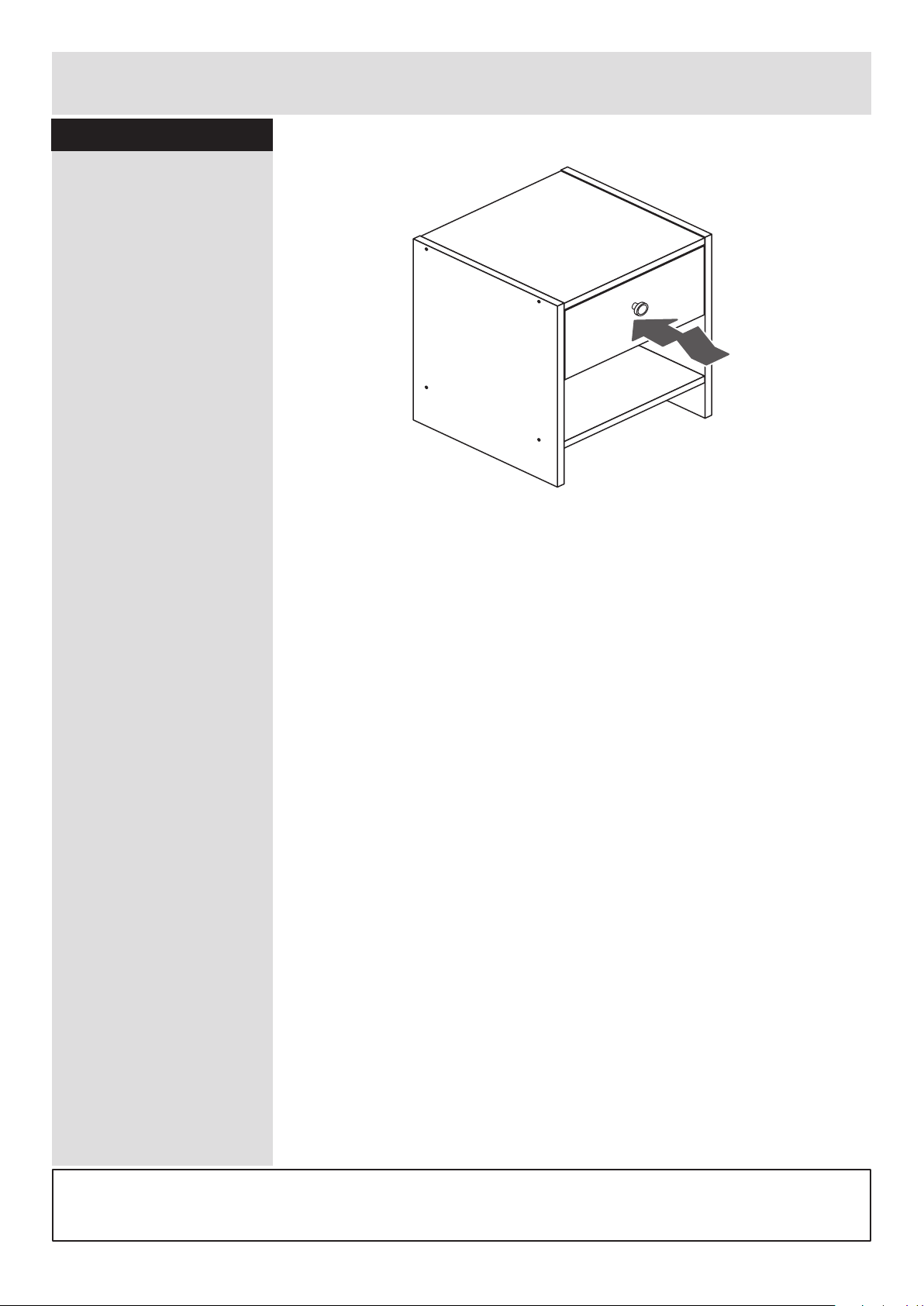
Insert the drawer
Lift the front of the
drawer whilst inserting to
overcome the ‘stop’
system.
Note: To ensure that
your drawer runs
smoothly, spray a small
amount of furniture
polish into the grooves.
Assembly is complete
Step 15
Page 11

Page 12

ALR2908
 Loading...