

Argos ZNS5D2-TB-AR ASSEMBLY INSTRUCTIONS
MADE IN
BRITAIN
Dimensions
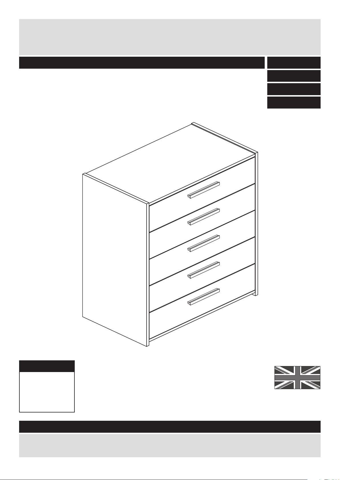
Width - 69cm
Depth - 40cm
Height - 88.5cm
New Sywell - 5 Drawer Chest
Assembly Instructions - Please keep for future reference
If you need help or have damaged or missing parts, call the Customer Helpline: 08456 400800
Issue 3 - 08/04/14
Important - Please read these instructions fully before starting assembly
257/7579
280/5935
282/2248
280/2110

Safety and Care Advice
Important - Please read these instructions fully before starting assembly
• Warning: This unit weighs
approximately 28.5kgs.
Please lift with care.
• Check you have all the
components and tools listed on
pages 2 and 3.
• Remove all fittings from the
plastic bags and separate them
into their groups.
• Keep children and animals
away from the work area, small
parts could choke if swallowed.
• Parts of the assembly will be
easier with 2 people.
• Make sure you have enough
space to layout the parts before
starting.
• Do not stand or put weight on
the product, this could cause
damage.
• Assemble the item as close to
its final position (in the same
room) as possible.
• Assemble on a soft level
surface to avoid damaging the
unit or your floor (use opened
out unit carton).
1
Care and maintenance
• Only clean using a damp cloth
and mild detergent, do no use
bleach or abrasive cleaners.
• From time to time check that
there are no loose screws on
this unit.
• This product should not be
discarded with household
waste. Take to your local
authority waste disposal centre.
Note: If required the next page
can be cut out and used as
reference throughout the
assembly. Keep this page with
these instructions for future
reference.
• We do not
recommend the
use of power
drill/drivers for
inserting screws,
as this could damage the unit.
Only use hand screwdrivers.
• Safety note: It is
recommended that this unit is
secured to a wall using the
bracket supplied.
• Dispose of all packaging
carefully and responsibly.
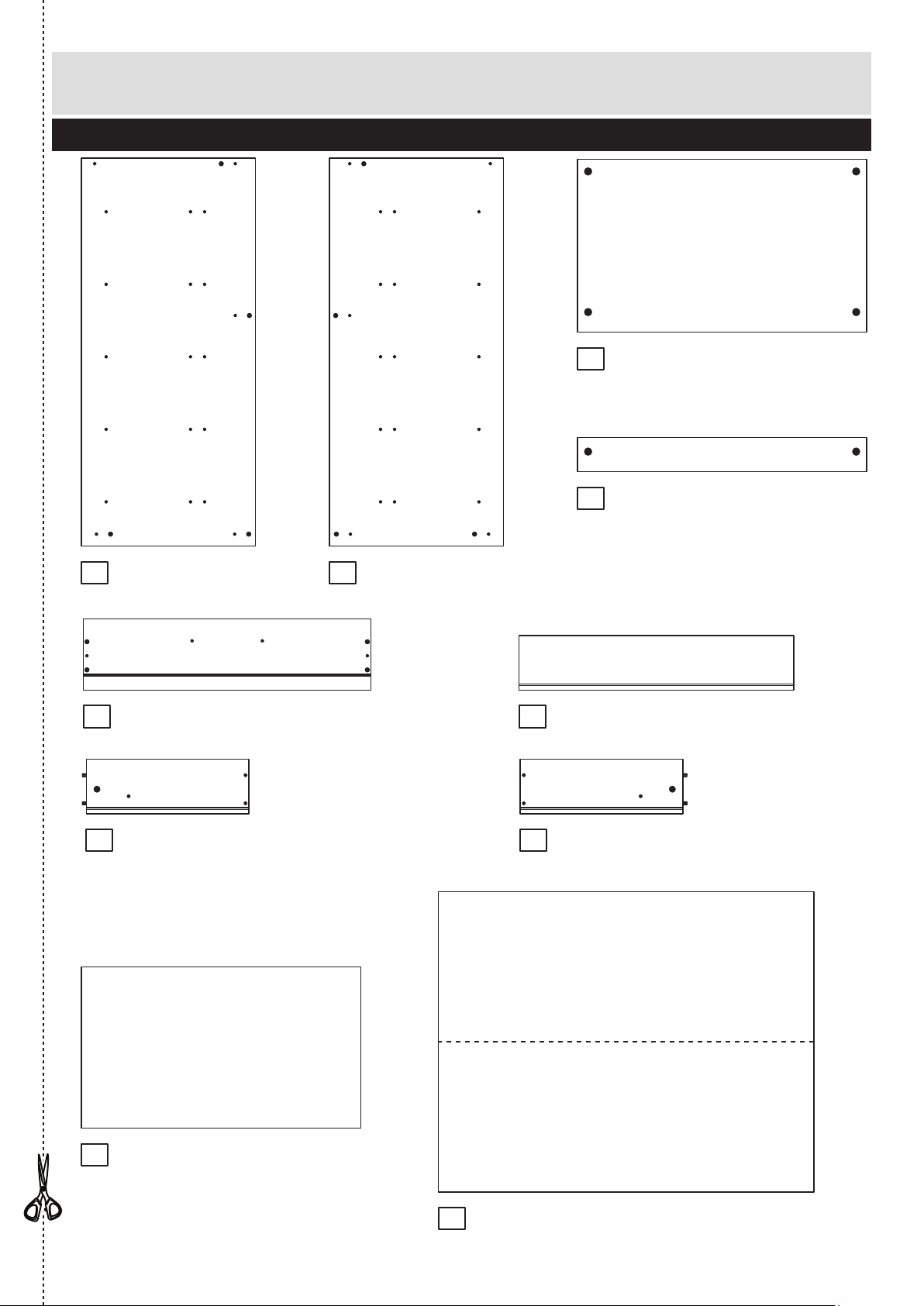
Components - Panels
Please check you have all the panels listed below
2
1
If you have damaged or missing components, call the
Customer Helpline: 08456 400800 quoting the reference
numbers below
Top (D2546A)
(658 x 394mm)
Drawer Front (D2550A)
(654 x 162mm) x 5
2
Rail (D2549A)
(658 x 78mm) x 3
3
4
5
10
Back (X684-524)
(854 x 684mm)
Left Side (D2552A)
(883 x 396mm)
Right Side (D2555A)
(883 x 396mm)
Drawer Base (T636-327)
(636 x 367mm) x 5
Drawer Back (W625-124)
(625 x 124mm) x 5
9
6
7 8
Left Drawer Side (W370-124LH)
(370 x 124mm) x 5
Right Drawer Side (W370-124RH)
(370 x 124mm) x 5
6
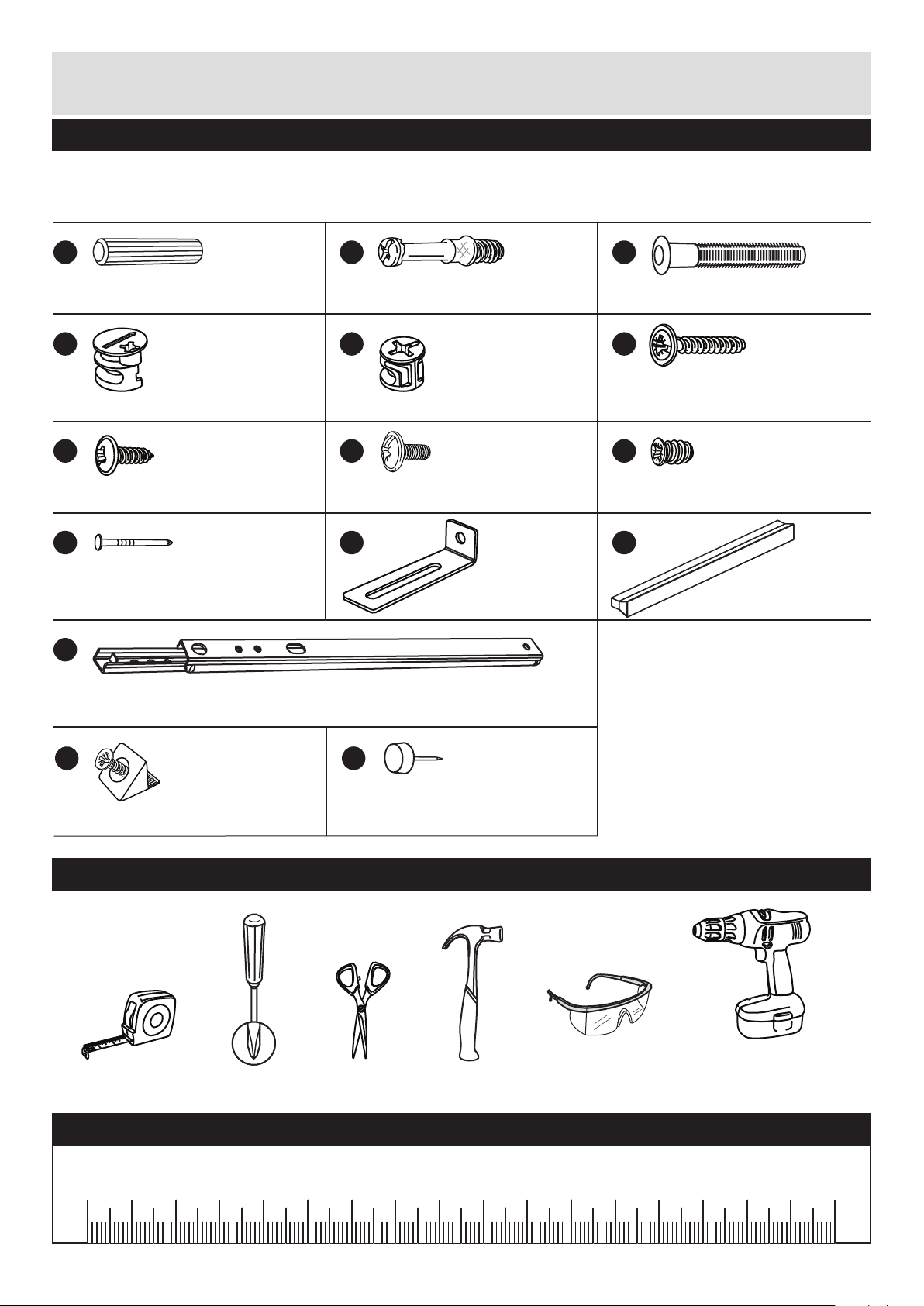
Please check you have all the fittings listed below
Tools required
3
Components - Fittings
If you have damaged or missing components, call the
Customer Helpline: 08456 400800 quoting the reference
numbers below
Note: The quantities below are the correct amount to complete the assembly. In some cases
more fittings may be supplied than are required.
A
Wooden dowel (F22) x 8
B
Metal dowel (F901) x 20
C
D E F
G H I
L
Rule Scissors Hammer
Eye protection
(when using a
hammer or drill)
Cross-head
screwdriver
Ruler - Use this ruler to help correctly identify the screws
mm 10 20 30 40 50 60 70 80 90 100 110 120 130 140 150 160 170
M
J K
9mm Screw (F74) x 10 9mm Screw (F73) x 20
Drawer runner (F1004) x 10
Electric drill
(do not use for
fitting screws)
Knock-in Peg (F171) x 20
13mm Screw (F79) x 1
Small locking
nut (F3) x 10
Large locking
nut (F900) x 10
Nail (F51) x 21 Bracket (F327) x 1
Handle (F315) x 5
25mm Screw (F95) x 10
O
Plastic Nail (F91) x 4
N
Wedgefix (F639) x 20
Assembly Instructions
4
If you have damaged or missing components, call the
Customer Helpline: 08456 400800 quoting the reference
numbers below
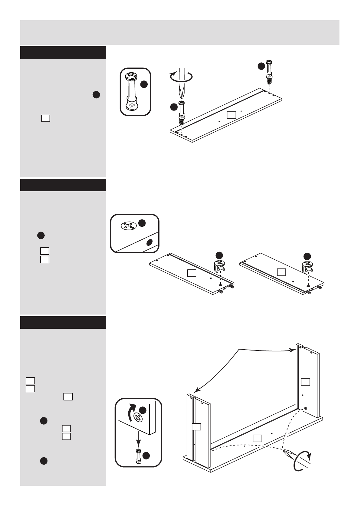
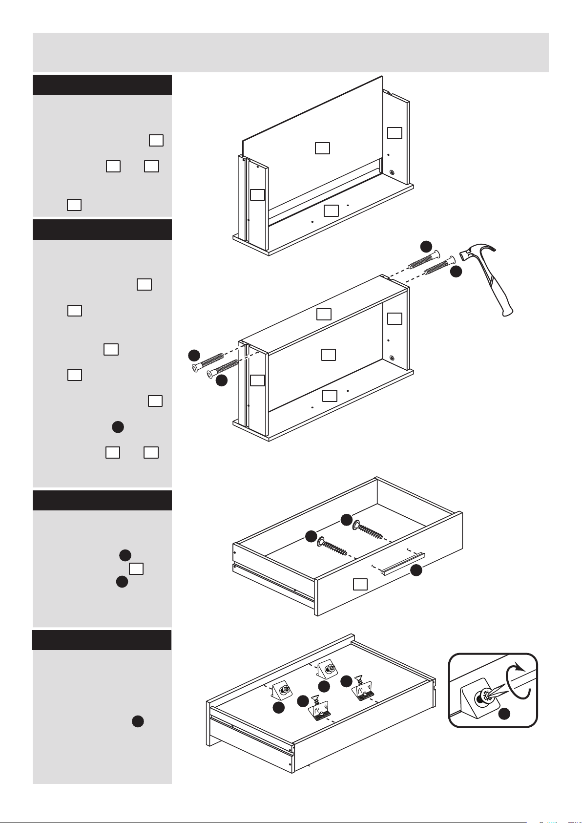
Step 1
x 5
B
Prepare the drawer
fronts
Screw 2 metal dowels
into the holes shown on
the back of each drawer
front .
Note: Tighten the metal
dowels up fully against
the panels.
B
5
Prepare the drawer
sides
Insert a small locking
nut into the hole
shown on the left drawer
side and right drawer
side .
Note: Arrow on locking
nut must point towards
hole in edge of panel.
E
7
8
Step 2
Step 3
B
B
5
Attach the drawer
sides to the drawer
front
Push the left drawer side
. and right drawer side
. onto the back of the
drawer front .
Turn the small locking
nuts on the left
drawer side and right
drawer side .
Note: Turn the locking
nuts clockwise to
secure panels - more
than 1/2 a turn.
7
8
5
E
7
8
E
x 5 x 5
x 5
Note: The locking nuts can be on
either surface of the drawer sides.
Make sure that the small groove
is on the inside, as shown.
E
B
B
E
Small groove
9
Note: Due to the manufacturing process, the holes for the
locking nut can be on either surface of the drawer sides.
E
E
7
8
8
7
5
Assembly Instructions
5
Step 4
Step 5
Fit the drawer base
Slide the drawer base
down the grooves in the
drawer sides and
and down into the
groove in the drawer
front .
9
7 8
5
Fit the drawer back
Fit the drawer back
down onto the drawer
base .
Make sure that the
drawer base fits into
the groove in the drawer
back .
Hold the drawer back
in position and tap the
knock-in pegs
through the holes in the
drawer sides and .
6
9
9
6
6
C
7 8
Attach the handles
Attach a handle to
each drawer front
using 2 screws .
L
F
Step 6
5
x 5
x 5
x 5
9
8
5
7
6
C
C
C
C
5
Step 7
Fit the wedgefixes
Turn the drawer
assemblies over and
slide 4 wedgefixes
into the front and back
grooves, as shown, and
tighten up the screws.
N
N
N
N
I
9
8
7
5
L
F
5
F
N
N
x 5
Finished
front edge
Assembly Instructions
6
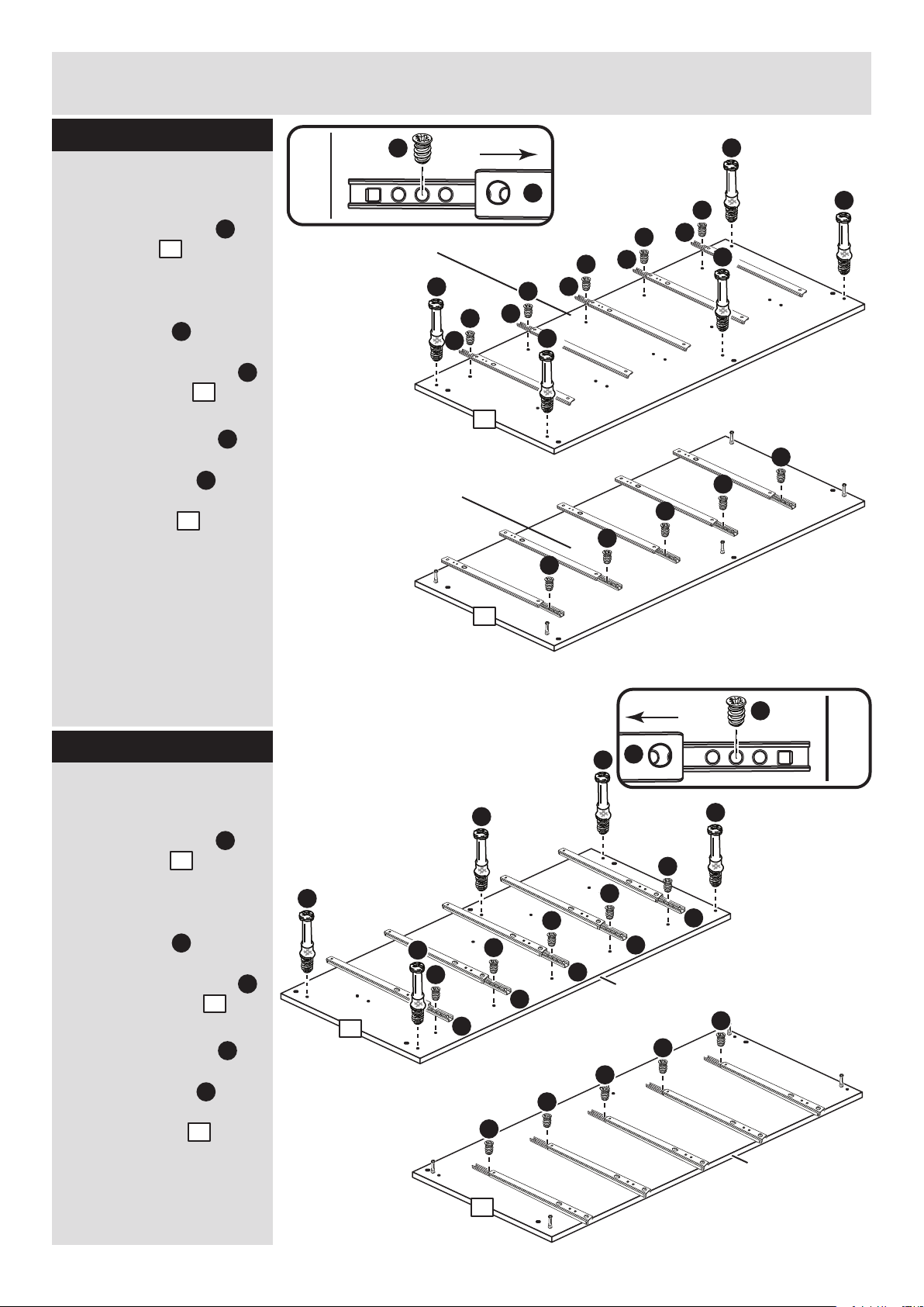
Step 8
Prepare the left side
a: Place 5 runners on
the left side . Slide
back the top of the
runner and use the 2nd
hole from the front to fit
the 1st screw .
Screw 5 metal dowels
into the left side .
b: Slide the runner
back the other way and
fit the 2nd screw into
the corresponding hole
in the left side .
M
1
Finished
front edge
I
M
I
B
1
M
I
1
Finished
front edge
I
M
Step 9
Prepare the right side
a: Place 5 runners on
the right side . Slide
back the top of the
runner and use the 2nd
hole from the front to fit
the 1st screw .
Screw 5 metal dowels
into the right side .
b: Slide the runner
back the other way and
fit the 2nd screw into
the corresponding hole
in the right side .
M
2
I
B
2
M
I
2
a:
b:
B
B
I
M
I
M
I
M
I
M
I
M
B
B
B
M
1
I
I
I
I
I
Finished
front edge
I
M
I
M
I
M
I
M
I
M
B
B
B
B
B
1
2
2
I
I
I
I
I
Finished
front edge
Finished
front edge
a:
b:
Finished
front edge
Finished
front edge
Assembly Instructions
7
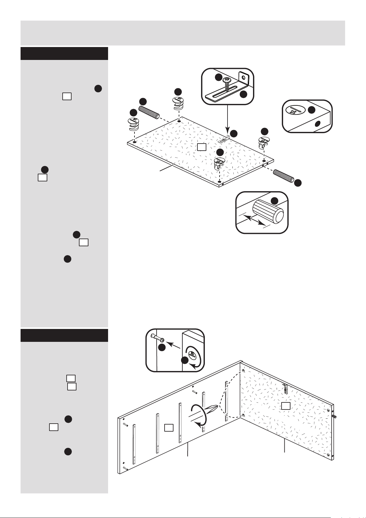
Step 10
Prepare the top
Tap 2 wooden dowels
into the top .
Note: Wooden dowels
must not stick out from
the edge by more than
10mm or they may
damage other panels.
Insert 4 large locking
nuts into the
top .
Note: The arrow on the
locking nut must point
towards the hole in the
edge of the panel.
Fix the bracket in the
middle of the top ,
flush to the back edge
using screw .
Fit the top to the right
side
Push the top onto
the right side .
Use a screwdriver to
tighten the 2 large
locking nuts fitted to
the top .
Note: Turn the large
locking nuts as far as
they will go - more than
1/2 a turn.
Step 11
D
10mm
A
A
3
D
3
3
2
D
3
D
B
D
plain chipboard surface
3
A
D
D
D
A
Finished
front edge
D
G
K
K
G
K
3
plain chipboard surface
3
2
 Loading...