

Page 1

MADE IN
BRITAIN
Dimensions
Width - 120cm
Depth - 59.5cm
Height - 181cm
Capella - 2+2 Sliding Robe
Assembly Instructions - Please keep for future reference
If you need help or have damaged or missing parts, call the Customer Helpline: 08456 400800
Issue 4 - 04/09/14
Important - Please read these instructions fully before starting assembly
268/1647
262/0488
244/0273
259/4071
Page 2
Safety and Care Advice
Important - Please read these instructions fully before starting assembly
• Warning: This unit weighs
approximately 79kgs.
Please lift with care.
• Check you have all the
components and tools listed on
pages 1, 2 and 3.
• Remove all fittings from the
plastic bags and separate them
into their groups.
• Keep children and animals
away from the work area, small
parts could choke if swallowed.
• Parts of the assembly will be
easier with 2 people.
• Make sure you have enough
space to layout the parts before
starting.
• Do not stand or put weight on
the product, this could cause
damage.
• Assemble the item as close to
its final position (in the same
room) as possible.
• Assemble on a soft level
surface to avoid damaging the
unit or your floor (use opened
out unit carton).
1
Care and maintenance
• Only clean using a damp cloth
and mild detergent, do no use
bleach or abrasive cleaners.
• From time to time check that
there are no loose screws on
this unit.
• This product should not be
discarded with household
waste. Take to your local
authority waste disposal centre.
• We do not
recommend the
use of power
drill/drivers for
inserting screws,
as this could damage the unit.
Only use hand screwdrivers.
• Safety note: It is
recommended that this unit is
secured to a wall using the
bracket supplied.
• Dispose of all packaging
carefully and responsibly.
Components - Panels
Please check you have all the panels listed below
1
If you have damaged or missing components, call the
Customer Helpline: 08456 400800 quoting the reference
numbers below
Top Drawer Front (D2716A)
(1165 x 185mm)
7
Bottom Drawer Front (D2718B)
(1165 x 244mm)
Top Drawer Back (W526-124)
(526 x 124mm) x 2
Bottom Left Drawer
Side (W370-165LH)
(370 x 165mm) x 2
Bottom Drawer Back (W526-165)
(526 x 165mm) x 2
2
3
4 5
Bottom Right Drawer
Side (W370-165RH)
(370 x 165mm) x 2
6
8 9
Drawer Base (T537-367)
(537 x 367mm) x 4
Top Left Drawer
Side (W370-124LH)
(370 x 124mm) x 2
Top Right Drawer
Side (W370-124RH)
(370 x 124mm) x 2
Page 3
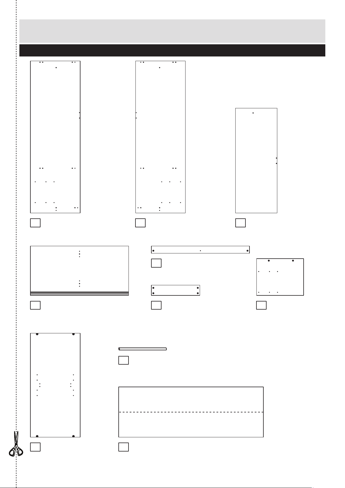
Components - Panels
Please check you have all the panels listed below
2
10
11 12
If you have damaged or missing components, call the
Customer Helpline: 08456 400800 quoting the reference
numbers below
Left Side (D2710A)
(1808 x 592mm)
13
Right Side (D2711A)
(1808 x 592mm)
Top/Base (D2709A)
(1169 x 587mm) x 2
Large Divider (D2712A)
(1246 x 496mm)
Rail (D2714A)
(1169 x 85mm) x 2
Back Rail (D2715A)
(577 x 120mm) x 2
Door (D2717A)
(1237 x 592mm) x 2
15
14
Small Divider (D2713A)
(437.5 x 560mm)
16
17 19
Hanging Rail (FHR569)
(566mm long) x 2
18
Back (X1722-597)
(1722 x 597mm) x 2
Page 4
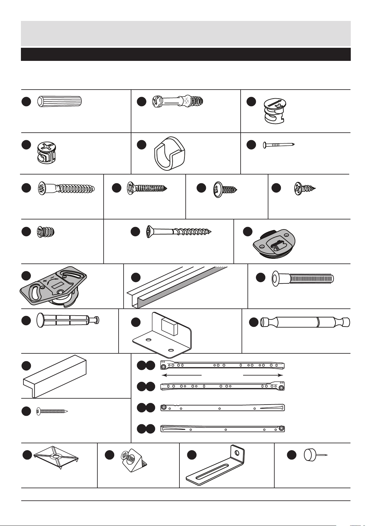
Please check you have all the fittings listed below
3
Components - Fittings
If you have damaged or missing components, call the
Customer Helpline: 08456 400800 quoting the reference
numbers below
Note: The quantities below are the correct amount to complete the assembly. In some cases
more fittings may be supplied than are required.
A
Wooden dowel (F22) x 16
C
D E F
G
40mm Screw (F910) x 4
13mm Screw (F63) x 38
Rail holder
(F1014) x 4
JH
K
I
Top glide
(F956) x 4
Bottom glide
(F952) x 4
M
N
Q
L
P
Bracket (F327) x 1
1167mm Track (F221) x 4
O
B
Metal dowel (F901) x 22
Large locking
nut (F900) x 22
Nail (F51) x 40
13mm Screw (F79) x 1
25mm Screw (F50) x 12
Buffer bracket
(F261) x 1
R
X Y
Small locking
nut (F3) x 8
Knock-in Peg (F171GY) x 16
Mushroom Head Pin (F260) x 4
S
T
R Runner (F160) x 4
b
L Runner (F161) x 4
T
c
L Runner (F159) x 4
T
a
R Runner (F162) x 4
T
d
350mm long
9mm Screw (F73) x 24
U
Double metal dowel (F566) x 2
V
Nail screw (F277) x 5
Wedgefix (F639) x 16
45mm Screw (F65) x 1
Handle (F930) x 6
Z
Plastic Nail (F91) x 6
W
Back holder (F276) x 5
These can also be round
Page 5
Assembly Instructions
4
If you have damaged or missing components, call the
Customer Helpline: 08456 400800 quoting the reference
numbers below
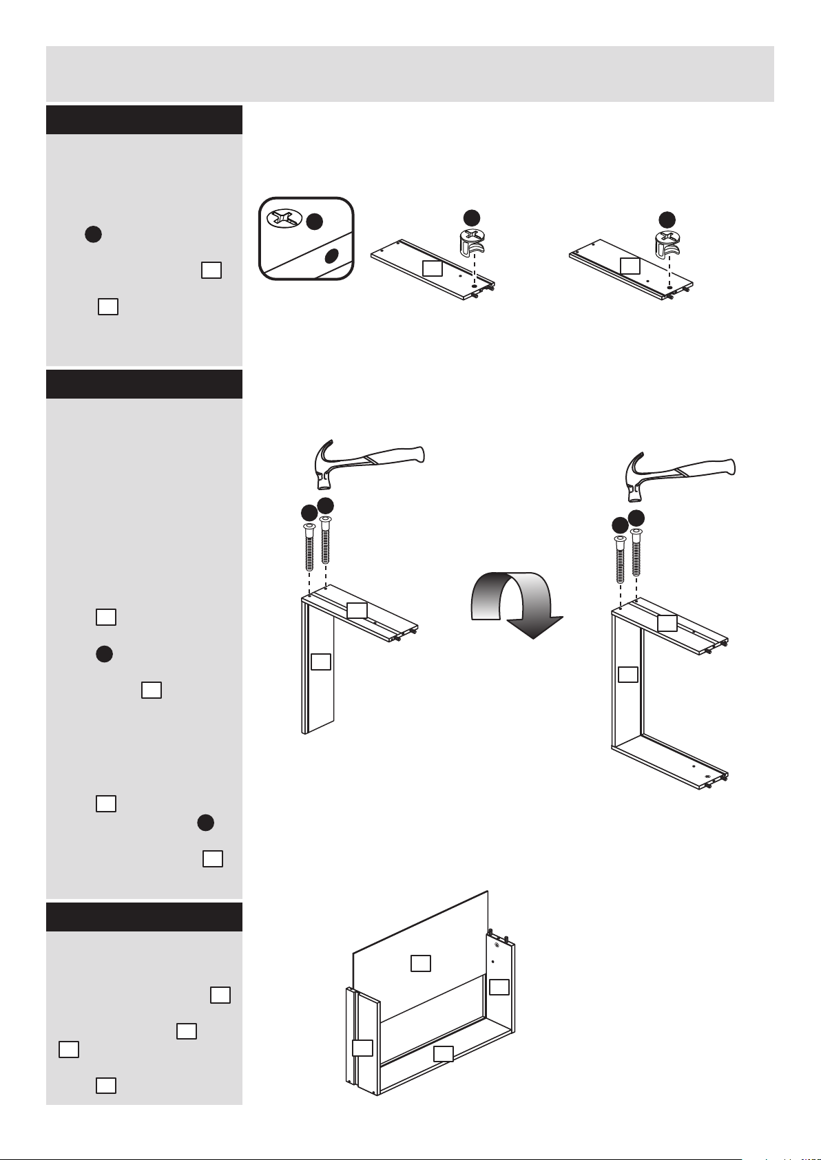
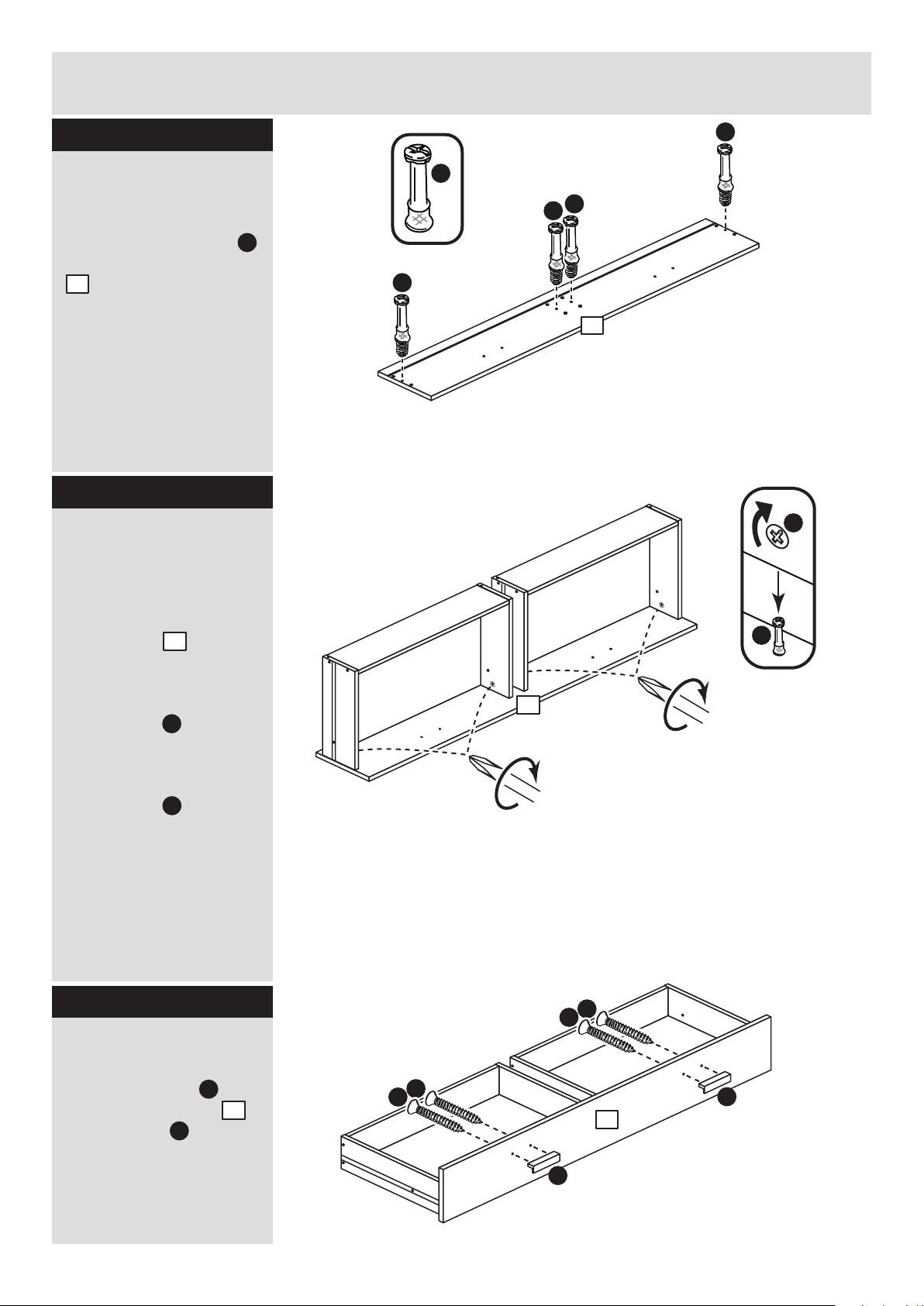
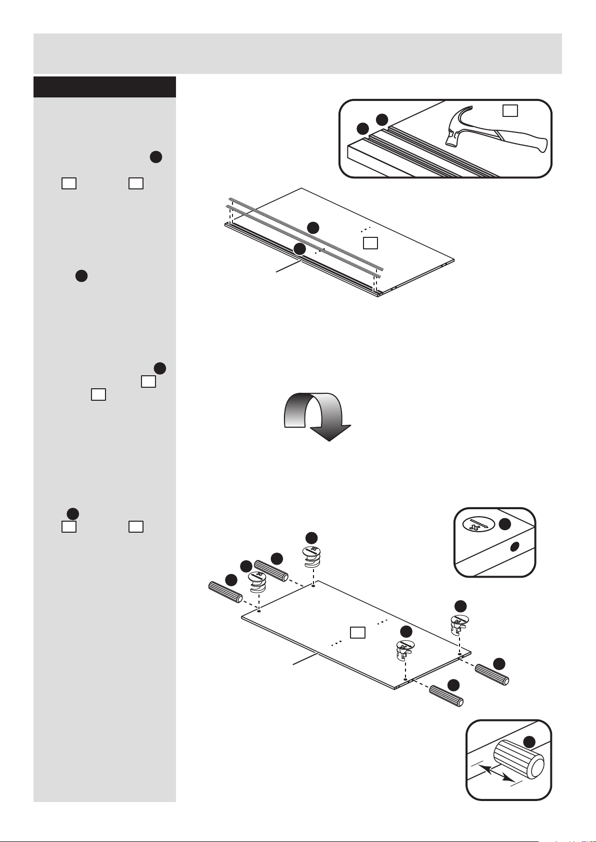
Step 1
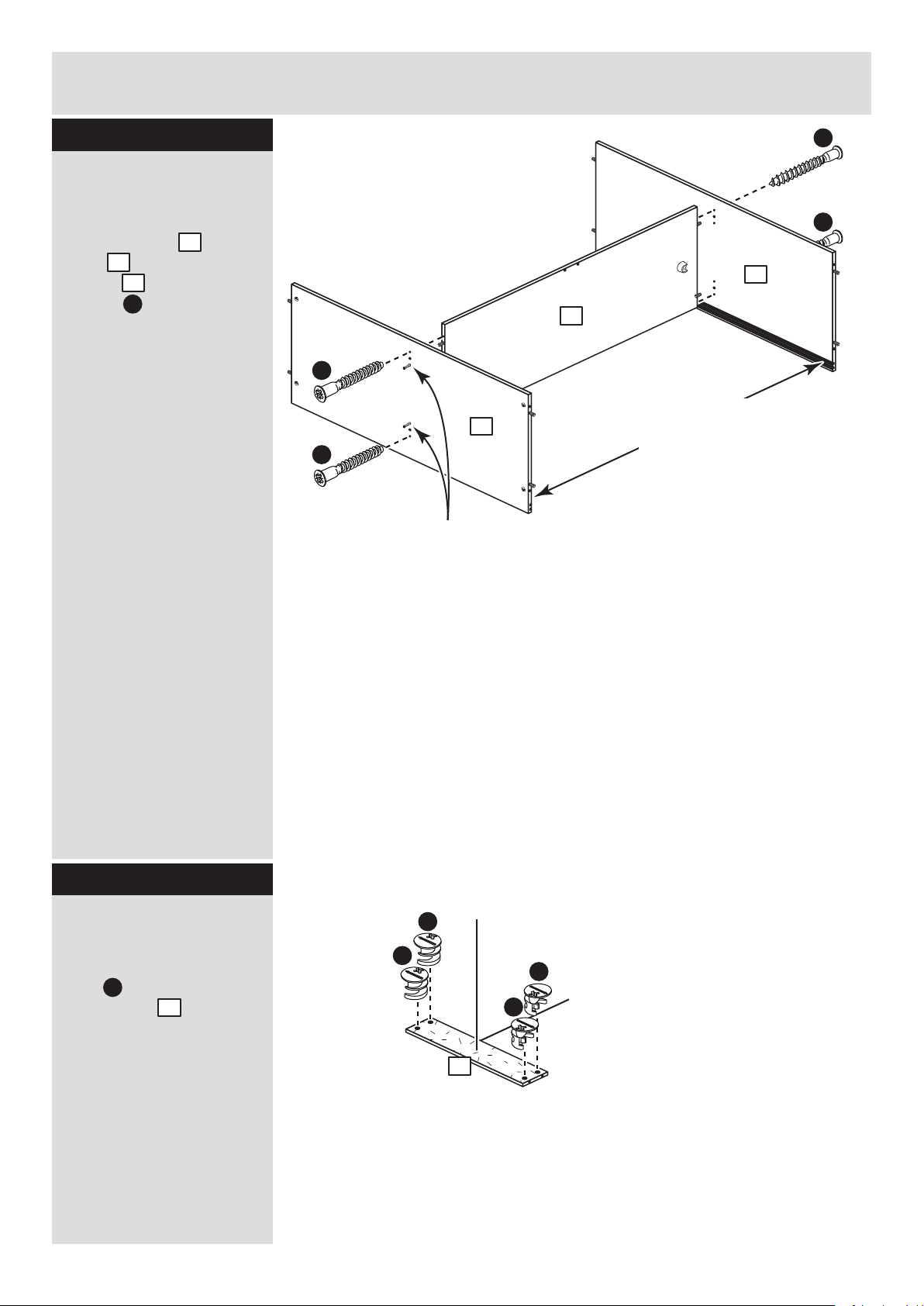
Step 2
Fit the top drawer
sides to the top
drawer backs
Make sure that the
grooves on the inside of
the drawer assembly line
up.
a: With the top drawer
back in an upright
position tap 2 knock-in
pegs through the
holes in the top left
drawer side .
Turn the assemblies
over
b: Hold the top drawer
back in position and
tap 2 knock-in pegs
through the holes in the
top right drawer side .
Step 3
Fit the drawer bases
Slide the drawer base
down the grooves in the
top drawer sides and
. and down into the
groove in the top drawer
back .
b:
a:
Turn the
assembly over
Prepare the 4 top
drawer sides
Insert a small locking
nut into the hole
shown on each of the 2
top left drawer sides
and 2 top right drawer
sides .
Note: The arrow on the
locking nut must point
towards the hole in the
edge of the panel.
D
3
4
D
x 2
x 2
x 2
x 2
x 2
7
P
3
7
P
4
9
3
4
7
P
P
P
P
7
7
9
7
3
Note: Due to the manufacturing process,
the holes for the locking nut can be on
either surface of the drawer sides.
D
D
3
4
3
4
4
Page 6
Assembly Instructions
5
Step 4
Fit the drawer front
Lower the 2 top drawer
assemblies down onto
the back of the top
drawer front .
Use a screwdriver to
tighten the 4 small
locking nuts fitted to
the drawer sides.
Note: Turn the small
locking nuts as far as
they will go - more than
1/2 a turn.
Step 5
B
Prepare the top
drawer front
Screw 4 metal dowels
into the top drawer front
. .
Note: Tighten the metal
dowels up fully against
the panels.
B
1
D
B
1
D
D
B
B
B
B
1
Attach the handles
Attach 2 handles to
the top drawer front
using screws .
U
H
Step 6
1
1
U
U
1
H
H
H
H
Page 7
Assembly Instructions
6
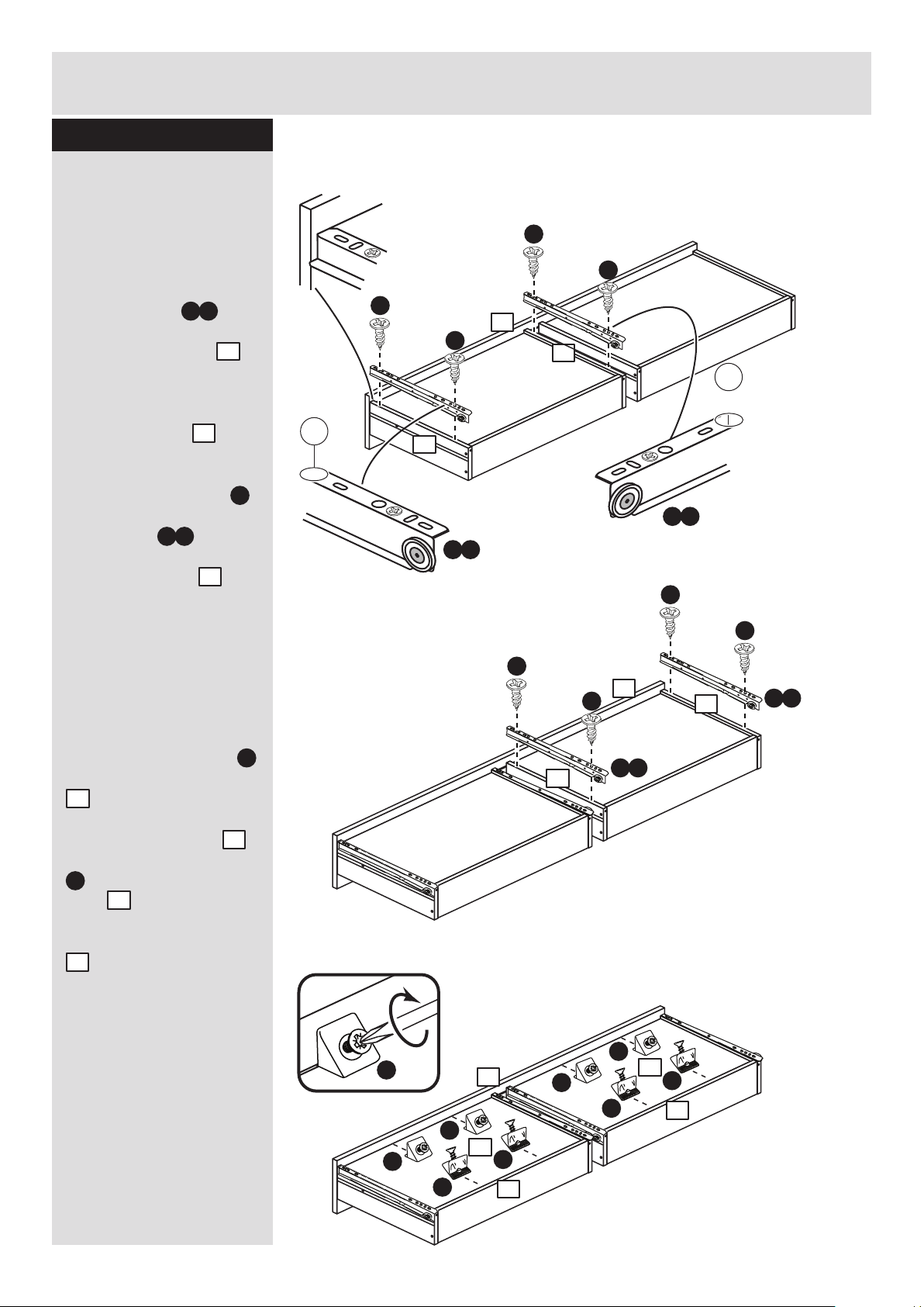
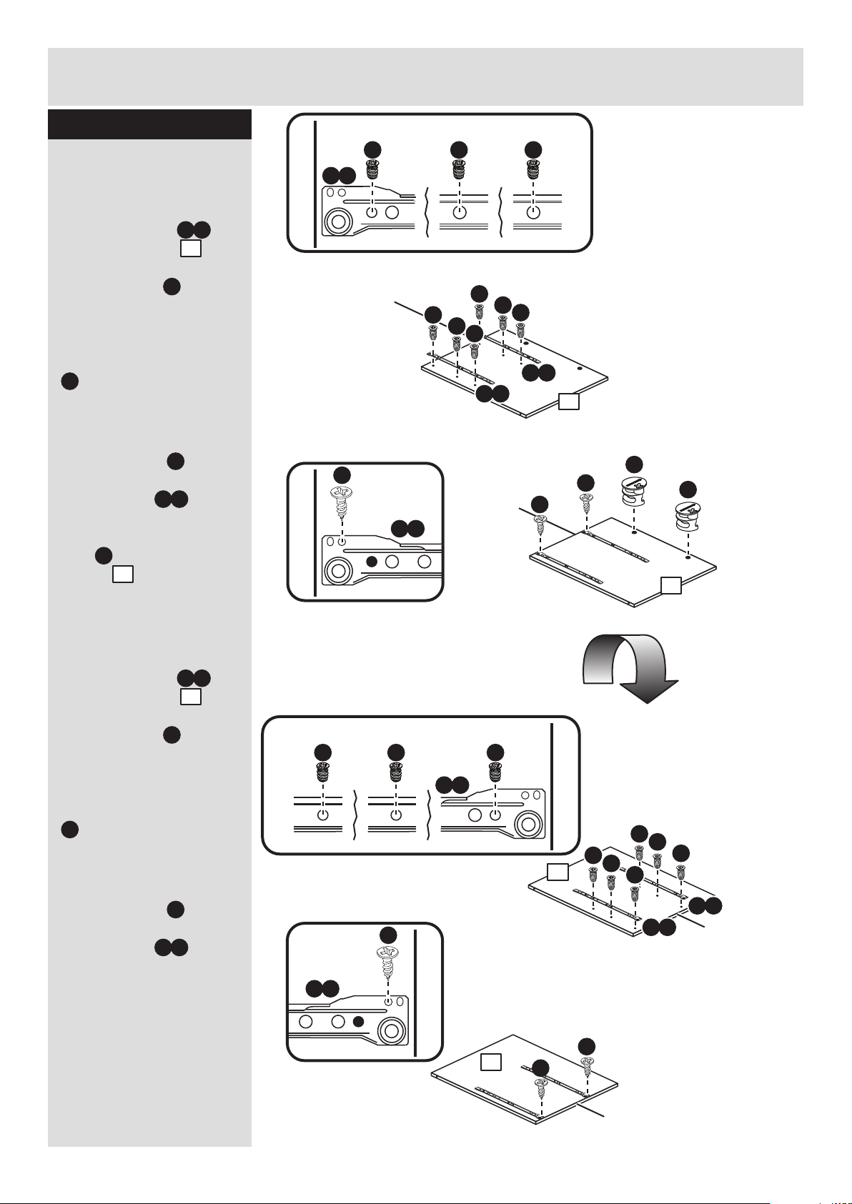
Step 7
Fit the runners and
the wedgefixes
Turn the top drawer
assembly over.
a: Fit a runner to
the bottom edge of the
top left drawer side ,
as shown, making sure
that it is pushed up
against the back of the
top drawer front . Use
a bradawl to mark the
fixing positions, then
secure with 2 screws .
Fit a runner to the
bottom edge of the top
right drawer side
using the same method.
b: Repeat the
instructions above to fit
the runners to the other
top drawer sides.
c: Slide 2 wedgefixes
along each drawer base
. and into the small
groove on the back of
the top drawer front .
Slide 2 more wedgefixes
. along each drawer
base and into the
small groove on the back
of the top drawer back
. .
Once in place, tighten up
the screws.
4
T c
3
1
J
T d
a:
b:
c:
Runners must be
pushed up against
the drawer front
J
J
J
J
L
T c
L
T d
R
R
J
J
J
J
T c
T d
4
1
4
3
1
X
X
X
X
X
X
X
X
X
X
X
9
9
1
7
9
9
1
7
7
3
Page 8
Assembly Instructions
7
Step 8
Step 9
Fit the bottom drawer
sides to the bottom
drawer backs
Make sure that the small
grooves on the inside of
the drawer assembly line
up.
a: With the bottom
drawer back in an
upright position tap 2
knock-in pegs
through the holes in the
bottom left drawer side
. .
Turn the assemblies
over
b: Hold the bottom
drawer back in
position and tap 2
knock-in pegs
through the holes in the
bottom right drawer side
. .
Step 10
Fit the drawer bases
Slide the drawer base
down the grooves in the
bottom drawer sides
and . and down into
the groove in the bottom
drawer back .
b:
a:
Turn the
assembly over
Prepare the 4 bottom
drawer sides
Insert a small locking
nut into the hole
shown on each of the 2
botom left drawer sides
. and 2 bottom right
drawer sides .
Note: The arrow on the
locking nut must point
towards the hole in the
edge of the panel.
D
5
6
D
x 2
x 2
x 2
x 2 x 2
8
P
5
8
P
6
9
5
6
8
D
D
5
6
P
P
P
P
5
6
8
8
9
5
6
8
Page 9
Assembly Instructions
8
Step 11
Fit the drawer front
Lower the 2 bottom
drawer assemblies down
onto the back of the
bottom drawer front .
Use a screwdriver to
tighten the 4 small
locking nuts fitted to
the drawer sides.
Note: Turn the small
locking nuts as far as
they will go - more than
1/2 a turn.
Step 12
B
Prepare the bottom
drawer front
Screw 4 metal dowels
into the bottom drawer
front .
B
2
D
B
2
D
D
B
B
B
B
Attach the handles
Attach 2 handles to
the bottom drawer front
. using screws .
U
H
Step 13
2
2
2
2
U
U
H
H
H
H
Page 10

Assembly Instructions
9
Step 14
Fit the runners and
the wedgefixes
Turn the bottom drawer
assembly over.
a: Fit a runner to
the bottom edge of the
bottom left drawer side
, as shown, making sure
that it is pushed up
against the back of the
bottom drawer front .
Use a bradawl to mark
the fixing positions, then
secure with 2 screws .
Fit a runner to the
bottom edge of the
bottom right drawer side
. using the same
method.
b: Repeat the
instructions above to fit
the runners to the other
bottom drawer sides.
c: Slide 2 wedgefixes
along each drawer base
. and into the small
groove on the back of
the bottom drawer front
. .
Slide 2 more wedgefixes
. along each drawer
base and into the
small groove on the back
of the bottom drawer
back .
Once in place, tighten up
the screws.
6
T c
5
2
J
T d
a:
b:
Runners must be
pushed up against
the drawer front
J
J
J
J
L
T c
L
T d
R
R
J
J
J
J
T d
T d
6
5
2
6
5
2
c:
X
X
X
X
X
X
X
X
9
9
X
X
9
9
2
8
X
8
8
2
Page 11
Assembly Instructions
10
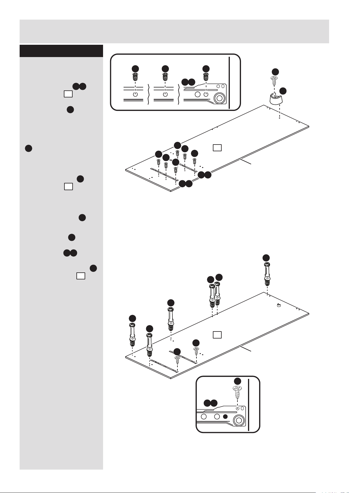
Step 15
A
A
A
O
Prepare the top and
base
Place 2 plastic tracks
down onto each of the
top and base
panels, making sure that
they are flush with the
edges of the panel.
Gently tap along the
length of the plastic
tracks until they are
fitted flat to the surface
of the panel.
Turn the top and the
base panels over
Tap 4 wooden dowels
into each of the top
and base panels.
Note: Wooden dowels
must not stick out from
the edge by more than
10mm or they may
damage other panels.
Insert 4 large locking
nuts into each of the
top and base
panels.
Note: The arrow on the
locking nut must point
towards the hole in the
edge of the panel.
10mm
A
13 13
O
13
13
O
O
13
Turn the top and
the base over
C
13 13
x 2
x 2
C
O
O
C
C
C
C
A
A
13
13
Finished
front edge
Finished
front edge
Page 12

Assembly Instructions
11
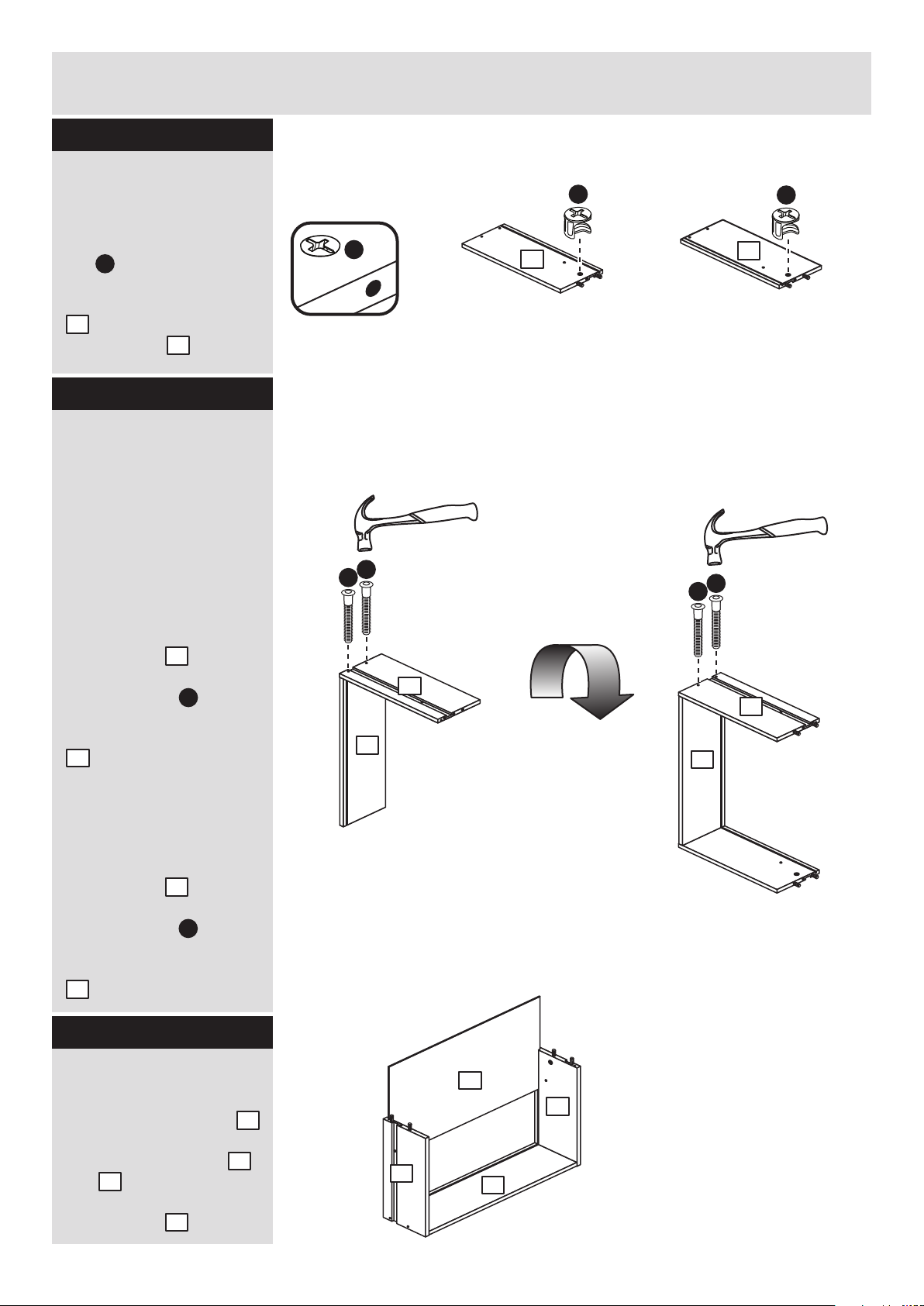
Step 16
Finish preparing the
base
Take 1 of the top/base
panels you have just
prepared and screw in 2
metal dowels .
This will now be used as
the base.
Step 17
A
A
Finished
front edge
Prepare the large
divider
Push a rail holder into
the large divider .
Make sure that it is fitted
straight, in line with the
panel edges and then
secure with screw .
Tap 4 wooden dowels
into the large divider .
Turn the large divider
over
Push a rail holder into
the other surface of the
large divider . Make
sure that it is fitted
straight, in line with the
panel edges and then
secure with screw .
E
12
E
12
Turn the large divider over
J
J
E
J
E
J
Finished
front edge
A
A
A
12
12
12
13
Finished
front edge
B
B
B
13
x 1
Page 13
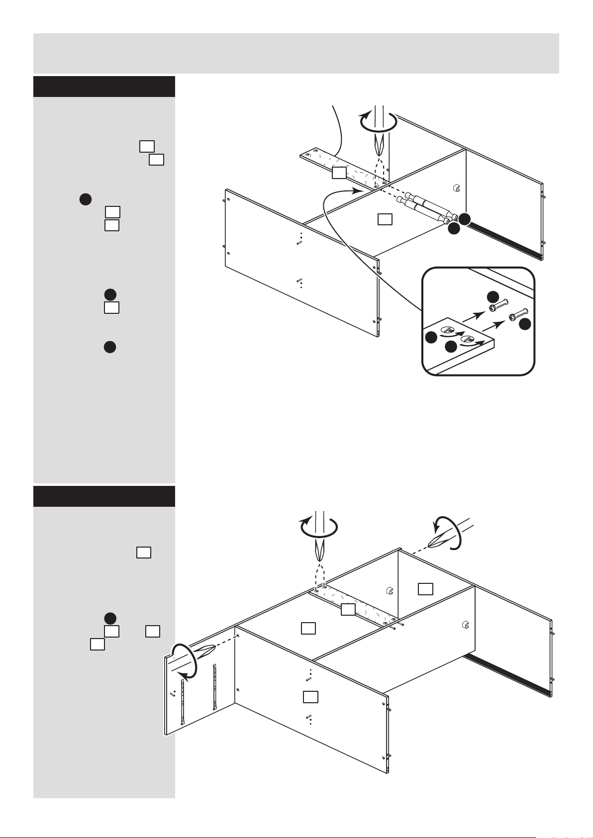
Fit top and base to
the divider
Attach the top and
base to the large
divider using 4
screws .
Finished
top edge
G
G
Assembly Instructions
12
Step 18
13
13
12
G
Step 19
Prepare the back rails
Insert 4 large locking
nuts into each of the
2 back rails .
15
C
G
G
Note: The plastic
tracks must be on
the inside surfaces
of the top and base
Note: The base is
the one that has
the 2 metal dowels.
13
Top
13
12
Base
C
C
C
C
Plain chipboard
surface
x 2
15
Page 14
Assembly Instructions
13
Step 20
E
J
T b
Finished front edge
J
Prepare the right side
a: Fit 2 runners to
the right side .
The 1st screw uses
the 1st hole in from the
front of the runner.
The 2nd and 3rd screws
. use the holes that line
up with the other panel
holes.
Push a rail holder into
the right side . Make
sure that it is fitted
straight, in line with the
panel edges and then
secure with screw .
b: Fit a screw into
the 2nd hole in at the top
of the runner .
Screw 6 metal dowels
into the right side .
K
K
T b
K
T b
11
K
K
J
T b
T b
Finished front edge
1st
screw
2nd
screw
3rd
screw
K K K
K
K
T b
K
B
B
B
B
B
B
J
J
B
11
E
11
J
a:
b:
11
11
Finished
front edge
Finished
front edge
Page 15
15
Assembly Instructions
14
Step 21
12
Fit a back rail
a: Push a back rail
onto the large divider .
Tap 2 double metal
dowels through the
large divider and into
the back rail until
they ‘’bottom out’’.
b: Use a screwdriver to
tighten the 2 large
locking nuts fitted to
the back rail .
Note: Turn the large
locking nuts as far as
they will go - more than
1/2 a turn.
15
12
S
Note: Support the
back rail until the
right side has been
fitted in the next step.
a:
12
15
C
C
15
Step 22
Fit the right side
Push the right side
onto the assembly.
Use a screwdriver to
tighten the 4 large
locking nuts fitted to
the back rail , top
and base .
11
C
15 13
13
S
S
C
S
C
S
b:
Finished
top edge
15
13
13
11
Page 16

A
b:
b:
Assembly Instructions
15
Step 23
a:
a:Qa:
Q
a:
13
13
11
Fit the mushroom
head pins
a: Tap 2 mushroom
head pins into the
holes on the outside of
the right side and
into the top and
base .
b: Use a screwdriver to
tighten the 2 large
locking nuts fitted to
the top and base .
Q
11
13
13
C
13 13
Prepare the 2 rails
Tap 2 wooden dowels
into each of the 2 rails
. .
Insert 2 large locking
nuts into each of the
2 rails .
A
14
C
Step 24
C
C
A
Plain chipboard
surface
14
x 2
14
Page 17
Finished
front edge
Finished
front edge
Assembly Instructions
16
Step 25
T a
Finished front edge
J
J
J
T a
Finished front edge
1st
screw
2nd
screw
3rd
screw
K K K
K
T a
K
K
K
T a
K
K
C
C
T b
Finished front edge
J
K
K
T b
K
T b
Finished front edge
1st
screw
2nd
screw
3rd
screw
K K K
K
K
T b
K
J
J
Finished
front edge
Finished
front edge
Turn the small
divider over
Prepare the small
divider
a: Fit 2 runners to
the small divider .
The 1st screw uses
the 1st hole in from the
front of the runner.
The 2nd and 3rd screws
. use the holes that line
up with the other panel
holes.
b: Fit a screw into
the 2nd hole in at the top
of the runner .
Insert 2 large locking
nuts into the small
divider .
Turn the small divider
over
c: Fit 2 runners to
the small divider .
The 1st screw uses
the 1st hole in from the
front of the runner.
The 2nd and 3rd screws
. use the holes that line
up with the other panel
holes.
d: Fit a screw into
the 2nd hole in at the top
of the runner .
T a
16
K
K
J
T a
T b
16
K
K
J
T b
C
16
a:
b:
c:
d:
16
16
16
16
Page 18

Finished
front edge
Assembly Instructions
17
Step 26
Finished
front edge
T a
Finished front edge
J
T a
Finished front edge
1st
screw
2nd
screw
3rd
screw
K K K
J
J
K
T a
K
K
K
T a
K
K
E
J
Prepare the left side
a: Fit 2 runners to
the left side .
The 1st screw uses
the 1st hole in from the
front of the runner.
The 2nd and 3rd screws
. use the holes that line
up with the other panel
holes.
Push a rail holder into
the left side . Make
sure that it is fitted
straight, in line with the
panel edges and then
secure with screw .
b: Fit a screw into
the 2nd hole in at the top
of the runner .
Screw 6 metal dowels
into the left side .
T a
10
K
K
J
T a
B
10
E
10
J
B
B
B
B
B
B
10
10
a:
b:
Page 19

Assembly Instructions
18
Step 27
Fit the small divider
Push the small divider
onto the base .
Use a screwdriver to
tighten the 2 large
locking nuts fitted to
the small divider .
C
Step 28
16
16
13
16
13
Fit the 2 rails and the
2nd back rail
Push the 2 rails onto
the right side .
Use a screwdriver to
tighten the 2 large
locking nuts fitted to
the rails .
Push the back rail
onto the large divider .
Use a screwdriver to
tighten the 2 large
locking nuts fitted to
the back rail .
14
14
11
C
15
C
14
14
11
15
12
Note: Support the 2 rails
and the back rail until the
left side has been fitted in
the next step.
15
12
Page 20

Assembly Instructions
19
Step 29
14
14
13
13
15
10
13
c:
13
10
Fit the left side
Push the left side
onto the assembly.
Use a screwdriver to
tighten the 6 large
locking nuts as
shown, fitted to the top
. , the base , the 2
rails and the back rail
. .
10
C
13
13
14
15
a:
b:
Q
a:
c:
Q
b:
Fit the mushroom
head pins
a: Tap 2 mushroom
head pins into the
holes on the outside of
the left side and into
the top and base .
b: Use a screwdriver to
tighten the 2 large
locking nuts fitted to
the top and base .
c: Fit the rail at the
back of the unit to the
small divider using
screw .
Q
10
13 13
C
13
14
16
13
Step 30
L
14
L
Page 21

Assembly Instructions
20
Step 31
Step 32
yxy
yy
The measurement from top corner X to bottom corner X must be
equal to the measurement from top corner Y to bottom corner Y
a:
Fit the back panels
a: Square up the unit by
making sure that
measurement x:x equals
y:y.
Place the 2 backs
down onto the unit as
shown.
Make sure that
the 2 backs are
pushed up tight
against each
other and that
they meet over
the back edge of
the large divider.
b: Nail around
the outside edges
19
F
Note: Do not
nail where the
backs meet.
b:
F
x
19
19
19
19
Secure the backs
Tap the nail screws
through the back holders
. and down between
the 2 backs into the
back edge of the large
divider.
Keep tapping the
nail screws in
until the back
holders dig
into the small
and large back.
Stand the unit up
for the next step.
V
W
19
V
W
Warning: The
unit is heavy.
Lift with care.
WV
+
WV
+
WV
+
WV
+
WV
+
Fit the 6 plastic nails
Tap 2 plastic nails
into the bottom edge of
each of the sides and
. and rail .
Z
10
11
14
Z
Z
Z
Z
Z
Z
10
11
14
V
W
W
Note: These can
also be round
Page 22

Assembly Instructions
Step 33
Step 34
Fit the 2 hanging rails
Push the hanging rails
into the rail holders
fitted to the side panels
and large divider.
18
E
18
E
18
18
Fit the 2 drawers
Slide the wheels of the
runners fitted to the
drawers, over the wheels
of the runners fitted to
the side panels and push
the drawers into position.
Panel
Drawer
21
Page 23

Assembly Instructions
22
Step 35
Prepare the right
hand door
Important: Check that
the holes are in the same
place as the diagram.
Push 2 top glides into
1 of the doors .
Push 2 bottom glides
into the same door
and secure each one
with 2 screws .
M
N
17
17
J
N
Prepare the left hand
door
Important: Check that
the holes are in the same
place as the diagram.
Fit the buffer bracket
onto the other door using
2 screws .
Push 2 top glides into
the door .
Push 2 bottom glides
into the door and
secure each one with 2
screws .
M
N
17
17
J
Step 36
R
J
J
J
M
M
J
J
N
J
J
N
M
M
J
J
N
J
J
N
This will be the
right hand door
J
R
J
R
This will be the
left hand door
17
17
Page 24

Small piece of
waste wood
Small piece of
waste wood
Assembly Instructions
Step 37
Drill 2 handle holes in
each of the doors
Important: Please follow
these instructions
carefully.
Lay the 2 doors
down onto a smooth
surface.
Check that the glides
and holes are in the
same place as the
diagrams.
Note: We recommend
the use of a small piece
of waste wood, placed
behind the holes while
drilling, to reduce the
possibility of any
breakout.
Using the pilot holes in
the rear face of the door,
drill through the 2 holes
indicated opposite, using
a 2.5mm diameter drill.
Turn the door over and
open out the 2.5mm
holes that you have just
drilled by drilling back
through them with a
5mm drill.
IMPORTANT
Carefully choose which 2 holes
you need to drill in each door
17
Buffer bracket
is on this door
ONLY drill these 2 holes
in the right hand door
ONLY drill these 2 holes
in the left hand door
17
17
23
Page 25

Assembly Instructions
24
Step 38
Fit the doors
a: With the top of the
right hand door
leaning back at an angle,
insert the bottom glides
. into the rear track .
Push the top of the right
hand door in and
locate the top glides
into the rear track .
b: With the top of the
left hand door
leaning back at an angle,
insert the bottom glides
. into the front track .
Push the top of the left
hand door in and
locate the top glides
into the front track .
Note: For more
information about fitting
the doors please refer to
the relevent diagrams.
To fit the top of the Doors
This lug fits
into the groove
in the track.
The switch in
the top glides
must be in this
position prior to
fitting the top of
the Doors.
You may have been supplied with a
top glide that differs slightly to the
one shown. It may have a switch that
just moves up and down and does
not lock into postion.
To fit the bottom of the Doors
When the top of
the Door is in
position, press the
switch to push lug
into the groove of
the track.
Left hand door
Right hand door
17
17
N
N M M
O
N
O
O
M
17
17
O
M
a:
b:
17
17
Left hand
door
Right
hand door
Buffer bracket
Page 26

Assembly Instructions
Step 39
25
Adjust the doors if
needed
If your doors are not
running smoothly, please
follow these instructions
to adjust the bottom
glides.
IF YOUR DOORS DO NOT RUN SMOOTHLY
Before adjusting the doors, use a spirit level to check the base
(or top) of the unit is level, front-to-back and side-to-side in the
3 positions shown.
Use suitable packing pieces (not supplied) to make the unit
level BEFORE making any adjustment, as shown.
To raise the door, loosen the screws and
swivel the glide towards the ‘+’ arrow.
Re-tighten the screws.
To lower the door, loosen the screws and
swivel the glide towards the ‘-’ arrow.
Re-tighten the screws.
Once the doors have been adjusted and
are running smoothly, use 2 screws to
hold each of the bottom glides in position.
J J
J
Page 27

Assembly Instructions
26
Step 40
Attach the handles
Attach a handle to
each of the doors
using 2 screws .
U
H
17
17
U
U
17
H
H
Page 28

Assembly Instructions
27
If you need help or have damaged or missing parts, call the Customer Helpline: 08456 400800
and quote the reference numbers on the component pages.
Argos Ltd, 489-499 Avebury Boulevard, Central Milton Keynes, MK9 2NW
ALR2998
Step 41
Top of Unit
WALL
WALL
Back of Unit
Fit the bracket
To prevent possible
overbalancing, we
recommend that this unit
is secured to a suitable
wall by use of the
bracket fitted to the
top of the unit.
Fixings are not supplied,
as they will need to suit
the wall type and the
length of screw will
depend on the distance
from the back of the unit
to the wall.
Fix the bracket
loosely onto the top of
the unit using screw
and mark the wall for the
wall fixing.
Swivel the bracket
away from the wall and
drill a hole in the wall
using a suitable drill bit
and fit your wall fixing.
Swivel the bracket
back and fix the bracket
to the wall, then tighten
Screw .
Note: Take care when
drilling the wall that you
do not drill into any
pipes, wires etc.
If in doubt, consult an
expert.
Warning: The
unit is heavy.
Lift with care.
Assembly is complete
Y
Y
I
Y
Y
I
Y
I
Y
Y
Page 29

MADE IN
BRITAIN
Dimensions
Width - 120cm
Depth - 59.5cm
Height - 181cm
Capella - 2+2 Sliding Robe
Assembly Instructions - Please keep for future reference
If you need help or have damaged or missing parts, call the Customer Helpline: 03456 400800
Issue 5 - 15/01/15
Important - Please read these instructions fully before starting assembly
268/1647
262/0488
244/0273
259/4071
Page 30

Safety and Care Advice
Important - Please read these instructions fully before starting assembly
• Warning: This unit weighs
approximately 79kgs.
Please lift with care.
• Check you have all the
components and tools listed on
pages 1, 2 and 3.
• Remove all fittings from the
plastic bags and separate them
into their groups.
• Keep children and animals
away from the work area, small
parts could choke if swallowed.
• Parts of the assembly will be
easier with 2 people.
• Make sure you have enough
space to layout the parts before
starting.
• Do not stand or put weight on
the product, this could cause
damage.
• Assemble the item as close to
its final position (in the same
room) as possible.
• Assemble on a soft level
surface to avoid damaging the
unit or your floor (use opened
out unit carton).
1
Care and maintenance
• Only clean using a damp cloth
and mild detergent, do no use
bleach or abrasive cleaners.
• From time to time check that
there are no loose screws on
this unit.
• This product should not be
discarded with household
waste. Take to your local
authority waste disposal centre.
Components - Panels
Please check you have all the panels listed below
1
If you have damaged or missing components, call the
Customer Helpline: 03456 400800 quoting the reference
numbers below
Top Drawer Front (D2716A)
(1165 x 185mm)
7
Bottom Drawer Front (D2718B)
(1165 x 244mm)
Top Drawer Back (W526-124)
(526 x 124mm) x 2
Bottom Left Drawer
Side (W370-165LH)
(370 x 165mm) x 2
Bottom Drawer Back (W526-165)
(526 x 165mm) x 2
2
3
4 5
Bottom Right Drawer
Side (W370-165RH)
(370 x 165mm) x 2
6
8 9
Drawer Base (T537-367)
(537 x 367mm) x 4
Top Left Drawer
Side (W370-124LH)
(370 x 124mm) x 2
Top Right Drawer
Side (W370-124RH)
(370 x 124mm) x 2
• We do not
recommend the
use of power
drill/drivers for
inserting screws,
as this could damage the unit.
Only use hand screwdrivers.
• Safety note: It is
recommended that this unit is
secured to a wall using the
overbalance protector kit
supplied or, an alternative fixing
method of your choice.
• Dispose of all packaging
carefully and responsibly.
Page 31

Components - Panels
Please check you have all the panels listed below
2
10
11 12
If you have damaged or missing components, call the
Customer Helpline: 03456 400800 quoting the reference
numbers below
Left Side (D2710A)
(1808 x 592mm)
13
Right Side (D2711A)
(1808 x 592mm)
Top/Base (D2709A)
(1169 x 587mm) x 2
Large Divider (D2712A)
(1246 x 496mm)
Rail (D2714A)
(1169 x 85mm) x 2
Back Rail (D2715A)
(577 x 120mm) x 2
Door (D2717A)
(1237 x 592mm) x 2
15
14
Small Divider (D2713A)
(437.5 x 560mm)
16
17 19
Hanging Rail (FHR569)
(566mm long) x 2
18
Back (X1722-597)
(1722 x 597mm) x 2
Page 32

Please check you have all the fittings listed below
3
Components - Fittings
If you have damaged or missing components, call the
Customer Helpline: 03456 400800 quoting the reference
numbers below
Note: The quantities below are the correct amount to complete the assembly. In some cases
more fittings may be supplied than are required.
A
Wooden dowel (F22) x 16
C
D E F
G
40mm Screw (F910) x 4
13mm Screw (F63) x 38
Rail holder
(F1014) x 4
JH
K
I
Top glide
(F956) x 4
Bottom glide
(F952) x 4
M
N
Q
L
P
1167mm Track (F221) x 4
O
B
Metal dowel (F901) x 22
Large locking
nut (F900) x 22
Nail (F51) x 40
25mm Screw (F50) x 12
Buffer bracket
(F261) x 1
R
X Y
Small locking
nut (F3) x 8
Knock-in Peg (F171GY) x 16
Mushroom Head Pin (F260) x 4
S
T
R Runner (F160) x 4
b
L Runner (F161) x 4
T
c
L Runner (F159) x 4
T
a
R Runner (F162) x 4
T
d
350mm long
9mm Screw (F73) x 24
Double metal dowel (F566) x 2
Wedgefix (F639) x 16
45mm Screw (F65) x 1
U
V
Nail screw (F277) x 5
Handle (F930) x 6
Plastic Nail (F91) x 6
W
Back holder (F276) x 5
These can also be round
Strap
Screw
Washer x 2
Overbalance protector kit (F269) x 1
Page 33

Assembly Instructions
4
If you have damaged or missing components, call the
Customer Helpline: 03456 400800 quoting the reference
numbers below
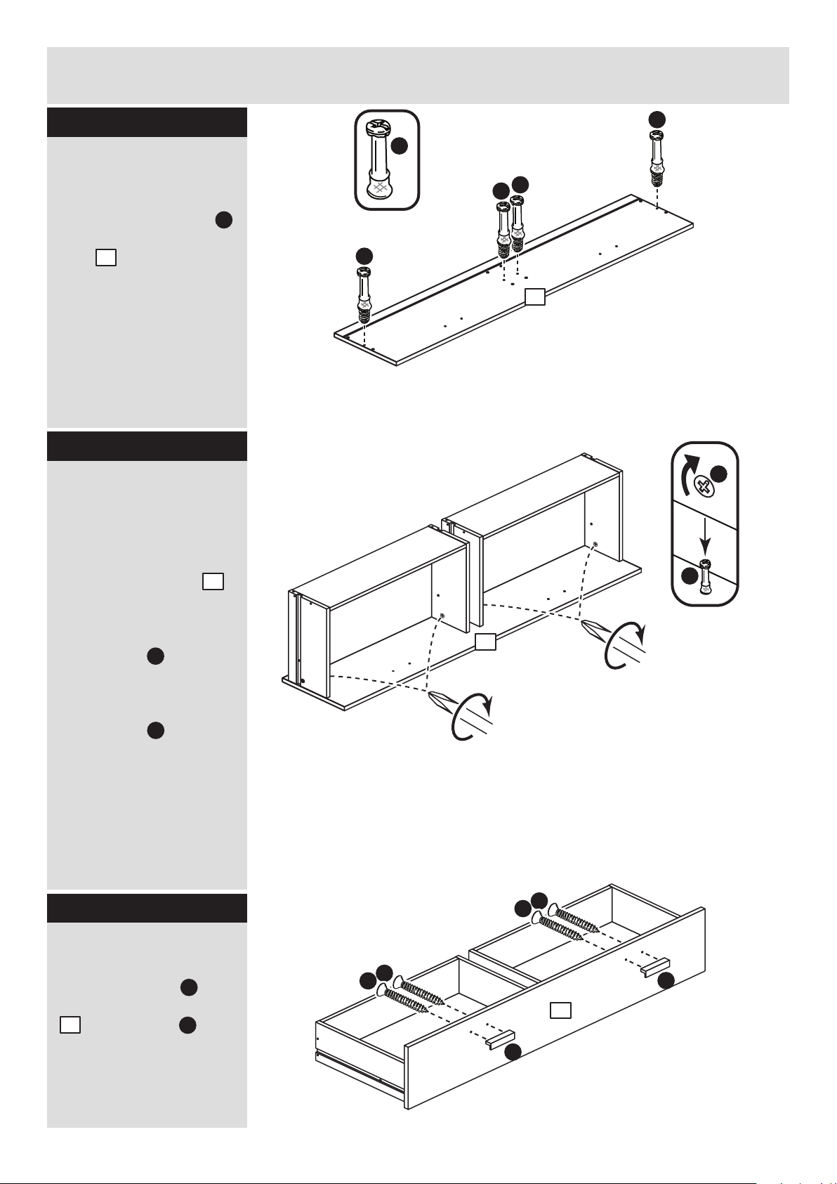
Step 1
Step 2
Fit the top drawer
sides to the top
drawer backs
Make sure that the
grooves on the inside of
the drawer assembly line
up.
a: With the top drawer
back in an upright
position tap 2 knock-in
pegs through the
holes in the top left
drawer side .
Turn the assemblies
over
b: Hold the top drawer
back in position and
tap 2 knock-in pegs
through the holes in the
top right drawer side .
Step 3
Fit the drawer bases
Slide the drawer base
down the grooves in the
top drawer sides and
. and down into the
groove in the top drawer
back .
b:
a:
Turn the
assembly over
Prepare the 4 top
drawer sides
Insert a small locking
nut into the hole
shown on each of the 2
top left drawer sides
and 2 top right drawer
sides .
Note: The arrow on the
locking nut must point
towards the hole in the
edge of the panel.
D
3
4
D
x 2
x 2
x 2
x 2
x 2
7
P
3
7
P
4
9
3
4
7
P
P
P
P
7
7
9
7
3
Note: Due to the manufacturing process,
the holes for the locking nut can be on
either surface of the drawer sides.
D
D
3
4
3
4
4
Page 34

Assembly Instructions
5
Step 4
Fit the drawer front
Lower the 2 top drawer
assemblies down onto
the back of the top
drawer front .
Use a screwdriver to
tighten the 4 small
locking nuts fitted to
the drawer sides.
Note: Turn the small
locking nuts as far as
they will go - more than
1/2 a turn.
Step 5
B
Prepare the top
drawer front
Screw 4 metal dowels
into the top drawer front
. .
Note: Tighten the metal
dowels up fully against
the panels.
B
1
D
B
1
D
D
B
B
B
B
1
Attach the handles
Attach 2 handles to
the top drawer front
using screws .
U
H
Step 6
1
1
U
U
1
H
H
H
H
Page 35

Assembly Instructions
6
Step 7
Fit the runners and
the wedgefixes
Turn the top drawer
assembly over.
a: Fit a runner to
the bottom edge of the
top left drawer side ,
as shown, making sure
that it is pushed up
against the back of the
top drawer front . Use
a bradawl to mark the
fixing positions, then
secure with 2 screws .
Fit a runner to the
bottom edge of the top
right drawer side
using the same method.
b: Repeat the
instructions above to fit
the runners to the other
top drawer sides.
c: Slide 2 wedgefixes
along each drawer base
. and into the small
groove on the back of
the top drawer front .
Slide 2 more wedgefixes
. along each drawer
base and into the
small groove on the back
of the top drawer back
. .
Once in place, tighten up
the screws.
4
T c
3
1
J
T d
a:
b:
c:
Runners must be
pushed up against
the drawer front
J
J
J
J
L
T c
L
T d
R
R
J
J
J
J
T c
T d
4
1
4
3
1
X
X
X
X
X
X
X
X
X
X
X
9
9
1
7
9
9
1
7
7
3
Page 36

Assembly Instructions
7
Step 8
Step 9
Fit the bottom drawer
sides to the bottom
drawer backs
Make sure that the small
grooves on the inside of
the drawer assembly line
up.
a: With the bottom
drawer back in an
upright position tap 2
knock-in pegs
through the holes in the
bottom left drawer side
. .
Turn the assemblies
over
b: Hold the bottom
drawer back in
position and tap 2
knock-in pegs
through the holes in the
bottom right drawer side
. .
Step 10
Fit the drawer bases
Slide the drawer base
down the grooves in the
bottom drawer sides
and . and down into
the groove in the bottom
drawer back .
b:
a:
Turn the
assembly over
Prepare the 4 bottom
drawer sides
Insert a small locking
nut into the hole
shown on each of the 2
botom left drawer sides
. and 2 bottom right
drawer sides .
Note: The arrow on the
locking nut must point
towards the hole in the
edge of the panel.
D
5
6
D
x 2
x 2
x 2
x 2 x 2
8
P
5
8
P
6
9
5
6
8
D
D
5
6
P
P
P
P
5
6
8
8
9
5
6
8
Page 37

Assembly Instructions
8
Step 11
Fit the drawer front
Lower the 2 bottom
drawer assemblies down
onto the back of the
bottom drawer front .
Use a screwdriver to
tighten the 4 small
locking nuts fitted to
the drawer sides.
Note: Turn the small
locking nuts as far as
they will go - more than
1/2 a turn.
Step 12
B
Prepare the bottom
drawer front
Screw 4 metal dowels
into the bottom drawer
front .
B
2
D
B
2
D
D
B
B
B
B
Attach the handles
Attach 2 handles to
the bottom drawer front
. using screws .
U
H
Step 13
2
2
2
2
U
U
H
H
H
H
Page 38

Assembly Instructions
9
Step 14
Fit the runners and
the wedgefixes
Turn the bottom drawer
assembly over.
a: Fit a runner to
the bottom edge of the
bottom left drawer side
, as shown, making sure
that it is pushed up
against the back of the
bottom drawer front .
Use a bradawl to mark
the fixing positions, then
secure with 2 screws .
Fit a runner to the
bottom edge of the
bottom right drawer side
. using the same
method.
b: Repeat the
instructions above to fit
the runners to the other
bottom drawer sides.
c: Slide 2 wedgefixes
along each drawer base
. and into the small
groove on the back of
the bottom drawer front
. .
Slide 2 more wedgefixes
. along each drawer
base and into the
small groove on the back
of the bottom drawer
back .
Once in place, tighten up
the screws.
6
T c
5
2
J
T d
a:
b:
Runners must be
pushed up against
the drawer front
J
J
J
J
L
T c
L
T d
R
R
J
J
J
J
T d
T d
6
5
2
6
5
2
c:
X
X
X
X
X
X
X
X
9
9
X
X
9
9
2
8
X
8
8
2
Page 39

Assembly Instructions
10
Step 15
A
A
A
O
Prepare the top and
base
Place 2 plastic tracks
down onto each of the
top and base
panels, making sure that
they are flush with the
edges of the panel.
Gently tap along the
length of the plastic
tracks until they are
fitted flat to the surface
of the panel.
Turn the top and the
base panels over
Tap 4 wooden dowels
into each of the top
and base panels.
Note: Wooden dowels
must not stick out from
the edge by more than
10mm or they may
damage other panels.
Insert 4 large locking
nuts into each of the
top and base
panels.
Note: The arrow on the
locking nut must point
towards the hole in the
edge of the panel.
10mm
A
13 13
O
13
13
O
O
13
Turn the top and
the base over
C
13 13
x 2
x 2
C
O
O
C
C
C
C
A
A
13
13
Finished
front edge
Finished
front edge
Page 40

Assembly Instructions
11
Step 16
Finish preparing the
base
Take 1 of the top/base
panels you have just
prepared and screw in 2
metal dowels .
This will now be used as
the base.
Step 17
A
A
Finished
front edge
Prepare the large
divider
Push a rail holder into
the large divider .
Make sure that it is fitted
straight, in line with the
panel edges and then
secure with screw .
Tap 4 wooden dowels
into the large divider .
Turn the large divider
over
Push a rail holder into
the other surface of the
large divider . Make
sure that it is fitted
straight, in line with the
panel edges and then
secure with screw .
E
12
E
12
Turn the large divider over
J
J
E
J
E
J
Finished
front edge
A
A
A
12
12
12
13
Finished
front edge
B
B
B
13
x 1
Page 41

Fit top and base to
the divider
Attach the top and
base to the large
divider using 4
screws .
Finished
top edge
G
G
Assembly Instructions
12
Step 18
13
13
12
G
Step 19
Prepare the back rails
Insert 4 large locking
nuts into each of the
2 back rails .
15
C
G
G
Note: The plastic
tracks must be on
the inside surfaces
of the top and base
Note: The base is
the one that has
the 2 metal dowels.
13
Top
13
12
Base
C
C
C
C
Plain chipboard
surface
x 2
15
Page 42

Assembly Instructions
13
Step 20
E
J
T b
Finished front edge
J
Prepare the right side
a: Fit 2 runners to
the right side .
The 1st screw uses
the 1st hole in from the
front of the runner.
The 2nd and 3rd screws
. use the holes that line
up with the other panel
holes.
Push a rail holder into
the right side . Make
sure that it is fitted
straight, in line with the
panel edges and then
secure with screw .
b: Fit a screw into
the 2nd hole in at the top
of the runner .
Screw 6 metal dowels
into the right side .
K
K
T b
K
T b
11
K
K
J
T b
T b
Finished front edge
1st
screw
2nd
screw
3rd
screw
K K K
K
K
T b
K
B
B
B
B
B
B
J
J
B
11
E
11
J
a:
b:
11
11
Finished
front edge
Finished
front edge
Page 43

15
Assembly Instructions
14
Step 21
12
Fit a back rail
a: Push a back rail
onto the large divider .
Tap 2 double metal
dowels through the
large divider and into
the back rail until
they ‘’bottom out’’.
b: Use a screwdriver to
tighten the 2 large
locking nuts fitted to
the back rail .
Note: Turn the large
locking nuts as far as
they will go - more than
1/2 a turn.
15
12
S
Note: Support the
back rail until the
right side has been
fitted in the next step.
a:
12
15
C
C
15
Step 22
Fit the right side
Push the right side
onto the assembly.
Use a screwdriver to
tighten the 4 large
locking nuts fitted to
the back rail , top
and base .
11
C
15 13
13
S
S
C
S
C
S
b:
Finished
top edge
15
13
13
11
Page 44

A
b:
b:
Assembly Instructions
15
Step 23
a:
a:Qa:
Q
a:
13
13
11
Fit the mushroom
head pins
a: Tap 2 mushroom
head pins into the
holes on the outside of
the right side and
into the top and
base .
b: Use a screwdriver to
tighten the 2 large
locking nuts fitted to
the top and base .
Q
11
13
13
C
13 13
Prepare the 2 rails
Tap 2 wooden dowels
into each of the 2 rails
. .
Insert 2 large locking
nuts into each of the
2 rails .
A
14
C
Step 24
C
C
A
Plain chipboard
surface
14
x 2
14
Page 45

Finished
front edge
Finished
front edge
Assembly Instructions
16
Step 25
T a
Finished front edge
J
J
J
T a
Finished front edge
1st
screw
2nd
screw
3rd
screw
K K K
K
T a
K
K
K
T a
K
K
C
C
T b
Finished front edge
J
K
K
T b
K
T b
Finished front edge
1st
screw
2nd
screw
3rd
screw
K K K
K
K
T b
K
J
J
Finished
front edge
Finished
front edge
Turn the small
divider over
Prepare the small
divider
a: Fit 2 runners to
the small divider .
The 1st screw uses
the 1st hole in from the
front of the runner.
The 2nd and 3rd screws
. use the holes that line
up with the other panel
holes.
b: Fit a screw into
the 2nd hole in at the top
of the runner .
Insert 2 large locking
nuts into the small
divider .
Turn the small divider
over
c: Fit 2 runners to
the small divider .
The 1st screw uses
the 1st hole in from the
front of the runner.
The 2nd and 3rd screws
. use the holes that line
up with the other panel
holes.
d: Fit a screw into
the 2nd hole in at the top
of the runner .
T a
16
K
K
J
T a
T b
16
K
K
J
T b
C
16
a:
b:
c:
d:
16
16
16
16
Page 46

Finished
front edge
Assembly Instructions
17
Step 26
Finished
front edge
T a
Finished front edge
J
T a
Finished front edge
1st
screw
2nd
screw
3rd
screw
K K K
J
J
K
T a
K
K
K
T a
K
K
E
J
Prepare the left side
a: Fit 2 runners to
the left side .
The 1st screw uses
the 1st hole in from the
front of the runner.
The 2nd and 3rd screws
. use the holes that line
up with the other panel
holes.
Push a rail holder into
the left side . Make
sure that it is fitted
straight, in line with the
panel edges and then
secure with screw .
b: Fit a screw into
the 2nd hole in at the top
of the runner .
Screw 6 metal dowels
into the left side .
T a
10
K
K
J
T a
B
10
E
10
J
B
B
B
B
B
B
10
10
a:
b:
Page 47

Assembly Instructions
18
Step 27
Fit the small divider
Push the small divider
onto the base .
Use a screwdriver to
tighten the 2 large
locking nuts fitted to
the small divider .
C
Step 28
16
16
13
16
13
Fit the 2 rails and the
2nd back rail
Push the 2 rails onto
the right side .
Use a screwdriver to
tighten the 2 large
locking nuts fitted to
the rails .
Push the back rail
onto the large divider .
Use a screwdriver to
tighten the 2 large
locking nuts fitted to
the back rail .
14
14
11
C
15
C
14
14
11
15
12
Note: Support the 2 rails
and the back rail until the
left side has been fitted in
the next step.
15
12
Page 48

Assembly Instructions
19
Step 29
14
14
13
13
15
10
13
c:
13
10
Fit the left side
Push the left side
onto the assembly.
Use a screwdriver to
tighten the 6 large
locking nuts as
shown, fitted to the top
. , the base , the 2
rails and the back rail
. .
10
C
13
13
14
15
a:
b:
Q
a:
c:
Q
b:
Fit the mushroom
head pins
a: Tap 2 mushroom
head pins into the
holes on the outside of
the left side and into
the top and base .
b: Use a screwdriver to
tighten the 2 large
locking nuts fitted to
the top and base .
c: Fit the rail at the
back of the unit to the
small divider using
screw .
Q
10
13 13
C
13
14
16
13
Step 30
L
14
L
Page 49

Assembly Instructions
20
Step 31
Step 32
yxy
yy
The measurement from top corner X to bottom corner X must be
equal to the measurement from top corner Y to bottom corner Y
a:
Fit the back panels
and plastic nails
a: Square up the unit by
making sure that
measurement x:x equals
y:y.
Place the 2 backs
down onto the unit as
shown.
Make sure that
the 2 backs are
pushed up tight
against each
other and that
they meet over
the back edge of
the large divider.
b: Nail around
the outside edges
of the 2 backs.
Tap 2 plastic nails
into the bottom edge of
each of the sides
and and rail .
19
F
Note: Do not
nail where the
backs meet.
b:
F
x
19
19
19
19
Secure the backs
Tap the nail screws
through the back holders
. and down between
the 2 backs into the
back edge of the large
divider.
Keep tapping the
nail screws in
until the back
holders dig
into the small
and large back.
Stand the unit up
for the next step.
V
W
19
V
W
Warning: The
unit is heavy.
Lift with care.
WV
+
WV
+
WV
+
WV
+
WV
+
I
10
11
14
I
I
I
I
I
I
10
11
14
V
W
W
Note: These can
also be round
Page 50

Assembly Instructions
Step 33
Step 34
Fit the 2 hanging rails
Push the hanging rails
into the rail holders
fitted to the side panels
and large divider.
18
E
18
E
18
18
Fit the 2 drawers
Slide the wheels of the
runners fitted to the
drawers, over the wheels
of the runners fitted to
the side panels and push
the drawers into position.
Panel
Drawer
21
Page 51

Assembly Instructions
22
Step 35
Prepare the right
hand door
Important: Check that
the holes are in the same
place as the diagram.
Push 2 top glides into
1 of the doors .
Push 2 bottom glides
into the same door
and secure each one
with 2 screws .
M
N
17
17
J
N
Prepare the left hand
door
Important: Check that
the holes are in the same
place as the diagram.
Fit the buffer bracket
onto the other door using
2 screws .
Push 2 top glides into
the door .
Push 2 bottom glides
into the door and
secure each one with 2
screws .
M
N
17
17
J
Step 36
R
J
J
J
M
M
J
J
N
J
J
N
M
M
J
J
N
J
J
N
This will be the
right hand door
J
R
J
R
This will be the
left hand door
17
17
Page 52

Small piece of
waste wood
Small piece of
waste wood
Assembly Instructions
Step 37
Drill 2 handle holes in
each of the doors
Important: Please follow
these instructions
carefully.
Lay the 2 doors
down onto a smooth
surface.
Check that the glides
and holes are in the
same place as the
diagrams.
Note: We recommend
the use of a small piece
of waste wood, placed
behind the holes while
drilling, to reduce the
possibility of any
breakout.
Using the pilot holes in
the rear face of the door,
drill through the 2 holes
indicated opposite, using
a 2.5mm diameter drill.
Turn the door over and
open out the 2.5mm
holes that you have just
drilled by drilling back
through them with a
5mm drill.
IMPORTANT
Carefully choose which 2 holes
you need to drill in each door
17
Buffer bracket
is on this door
ONLY drill these 2 holes
in the right hand door
ONLY drill these 2 holes
in the left hand door
17
17
23
Page 53

Assembly Instructions
24
Step 38
Fit the doors
a: With the top of the
right hand door
leaning back at an angle,
insert the bottom glides
. into the rear track .
Push the top of the right
hand door in and
locate the top glides
into the rear track .
b: With the top of the
left hand door
leaning back at an angle,
insert the bottom glides
. into the front track .
Push the top of the left
hand door in and
locate the top glides
into the front track .
Note: For more
information about fitting
the doors please refer to
the relevent diagrams.
To fit the top of the Doors
This lug fits
into the groove
in the track.
The switch in
the top glides
must be in this
position prior to
fitting the top of
the Doors.
You may have been supplied with a
top glide that differs slightly to the
one shown. It may have a switch that
just moves up and down and does
not lock into postion.
To fit the bottom of the Doors
When the top of
the Door is in
position, press the
switch to push lug
into the groove of
the track.
Left hand door
Right hand door
17
17
N
N M M
O
N
O
O
M
17
17
O
M
a:
b:
17
17
Left hand
door
Right
hand door
Buffer bracket
Page 54

Assembly Instructions
Step 39
25
Adjust the doors if
needed
If your doors are not
running smoothly, please
follow these instructions
to adjust the bottom
glides.
IF YOUR DOORS DO NOT RUN SMOOTHLY
Before adjusting the doors, use a spirit level to check the base
(or top) of the unit is level, front-to-back and side-to-side in the
3 positions shown.
Use suitable packing pieces (not supplied) to make the unit
level BEFORE making any adjustment, as shown.
To raise the door, loosen the screws and
swivel the glide towards the ‘+’ arrow.
Re-tighten the screws.
To lower the door, loosen the screws and
swivel the glide towards the ‘-’ arrow.
Re-tighten the screws.
Once the doors have been adjusted and
are running smoothly, use 2 screws to
hold each of the bottom glides in position.
J J
J
Page 55

Assembly Instructions
26
Step 40
Attach the handles
Attach a handle to
each of the doors
using 2 screws .
U
H
17
17
U
U
17
H
H
Page 56

Assembly Instructions
27
If you need help or have damaged or missing parts, call the Customer Helpline: 03456 400800
and quote the reference numbers on the component pages.
Argos Ltd, 489-499 Avebury Boulevard, Central Milton Keynes, MK9 2NW
ALR2998
Step 41
Fit the overbalance
protector kit
To prevent possible
overbalancing we
recommend that this unit
is secured to a suitable
wall by fitting of the
overbalance protector kit
. to the unit, or an
alternative fixing method
of your choice.
Wall fixings are not
supplied as they will
need to suit the wall
type.
Note: Take care when
drilling the wall that you
do not drill into any
pipes, wires etc.
If in doubt, consult an
expert.
Assembly is complete
Y
Y
WALL
Wall fixing
(not supplied)
Screw
(not supplied)
Washer
Strap
Y
Strap
Washer
Screw
TOP OF UNIT
Y
 Loading...