

Page 1
Wiltshire-
Bedside Chest 2 Drawers
Assembly Instructions
- Please keep for future reference
2626286
2478843
2572608
Dimensions
Width - 49.7cm
Depth - 42.5cm
Height- 52.2cm
Important
If you need help or have damaged or missing parts, call the
14-3E-218_01
– Please read these instructions fully before starting assembly
Customer Helpline:
03456 400 800
Issue 1 - 14/06/06
Page 2

Safety and Care Advice
Important – Please read these instructions fully before starting assembly
• Check you have all the
components and tools listed on
the following pages.
• Remove all fittings from the
plastic bags and separate them
into their groups.
• Keep children and animals
away from the work area, small
parts could choke if swallowed.
• Make sure you have enough
space to layout the parts before
starting.
Care and maintenance
• Only clean using a damp cloth
and mild detergent, do no use
bleach or abrasive cleaners.
• Do not stand or put weight on
the product, this could cause
damage.
• Assemble the item as close to
its final position (- in the same
room)as possible.
• Assemble on a soft level surface
to avoid damaging the unit or your
floor.
• Parts of the assembly will be
easier with 2 people.
• From time to time check that
there are no loose screws on
this unit.
• To reduce the
likelihood of
damaging your
product please
ensure that your
power drill is set
on a low torque
setting.
• This product should not be
discarded with household waste.
Take to your local authority
waste disposal centre.
Handy Hints
• Assemble all parts and bolts
loosely during assembly, only
once the product is complete
should you fully tighten bolts.
• Regularly check and ensure
that all bolts and fittings are
tightened properly.
1
Page 3

If you have damaged or missing commponents,
Components - Panels
call the
Please check you have all the panels listed below
Customer Helpline:
03456 400 800
Right side panel x 1
1
(39.5 x 49.9cm)
Bottom front support x 1
4
(35.7 x 7.1cm)
Bottom back support x 1
5
(35.7 x 7.1cm)
Bottom plinth x 1
9 11
(35.6 x 2cm)
2
6
Left side panel x 1
(39.5 x 49.9cm)
Back panel x 1
(37.7 x 41.8cm)
Right drawer side x 2
(35 x 10cm)
3
Top panel x 1 (49.7 x 42.5cm)
7
Right hinge frame x 1
(5.3 x 49.9cm)
8
Left hinge frame x 1
(5.3 x 49.9cm)
12
Left drawer side x 2
(35 x 10cm)
Handle x 2
15
(10.5 x 1.9cm)
20
Small drawer base x 2
(31.7 x 33.9cm)
Small drawer back x 2
18
(31.3 x 10cm)
19
Small drawer front x 2
(35 x 19cm)
2
Page 4
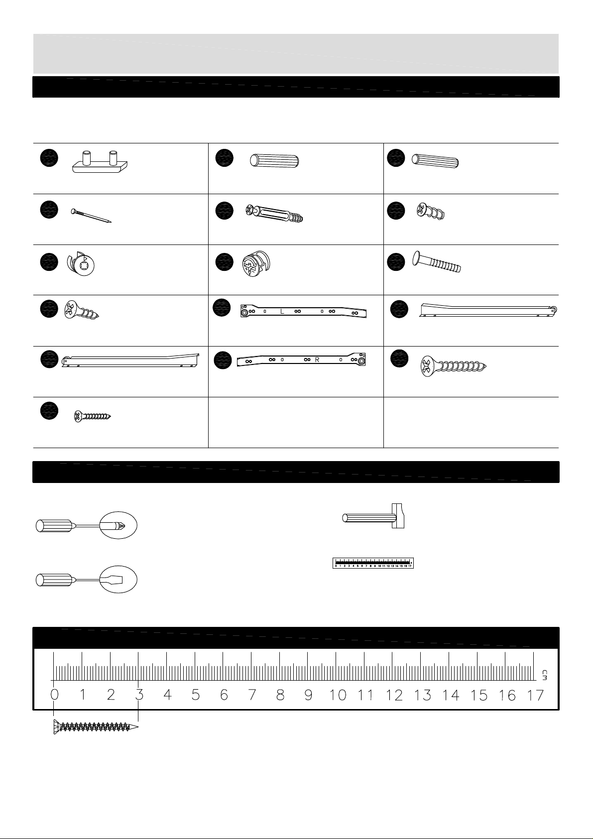
Components - Fittings
Please check you have all the fittings listed below
Note:
The quantities below are the correct amount to complete the assembly. In some cases more fittings may
be supplied than are required.
A
Feet x 4
D
Nail x 20
G
Large locking nut x 13
K
20mm Screw x 8
N
Runner right B x 2
B
8/30mm Wooden dowel x 16
E F
Screw x 17
H
Small locking nut x 4
L
Runner left A x 2
R
Runner right A x 2
C
6/30mm Wooden dowel x 8
9mm Screw x 8
J
Plastic dowel x 8
M
Runner left B x 2
S
30mm Screw x 4
4
Z
12mm Screw x 4
Tools required
Phillips screwdriver
(medium & large)
Flatblade screwdriver
(medium)
Ruler - Use this ruler to help correctly identify the screws
Hammer
Ruler/tape
measure
The screws length is measured from the head to the point (30mm screw shown)
3
Page 5
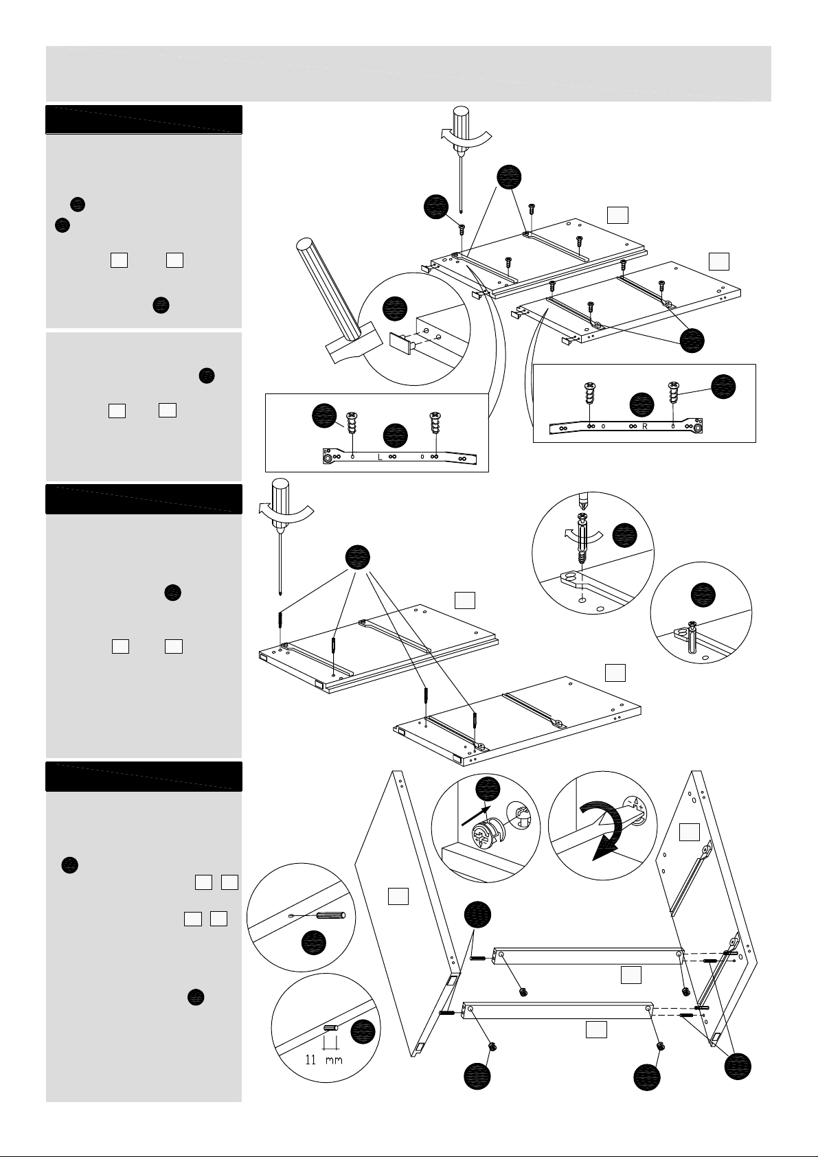
Assembly Instructions
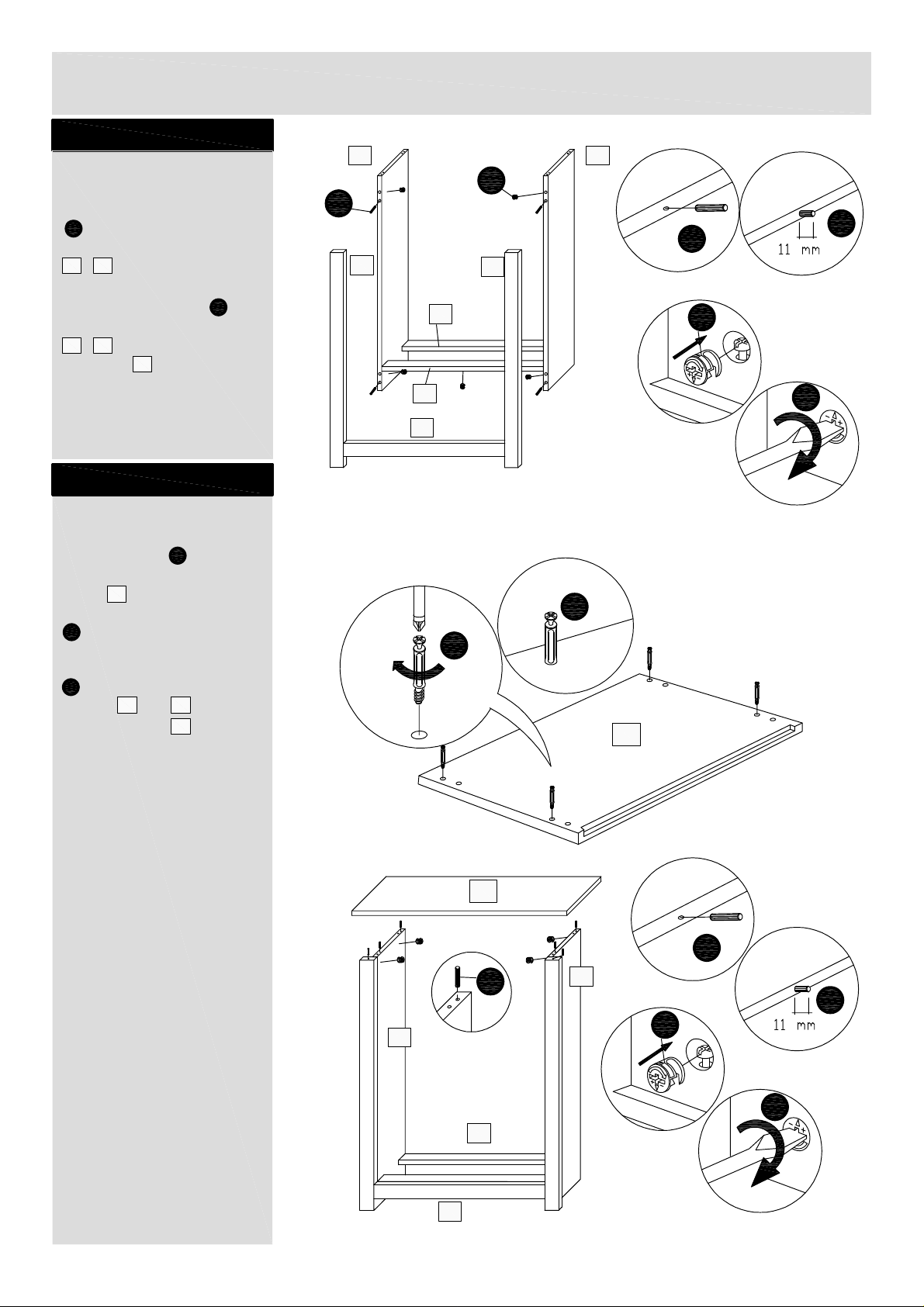
Step 1
Attaching runners
a: Position left runners
L
A
and right runners A
R
on to the drilled holes
of the left and right side
panels and .
Fix through holes shown
using screws .
1
2
F
b:
A
a:
L
F
2
1
b: Attaching feet
Position plastic feet
to the left and right side
1
panels
below and fix them using
the hammer.
and
Step 2
Preparation for the
attaching of bottom
supports
Insert screws into
the drilled holes of the
left and right side
1
panels
and .
2
A
from
A
E
2
R
F
R
F
L
E
E
2
1
E
Step 3
Attaching the bottom
supports
Insert wooden dowels
B
into the bottom front
and back support ,
and place on left and
right side panels , .
Align correctly and insert
large locking nuts and
turn them clockwise to
lock.
4
2
1
G
G
1
5
2
B
B
4
B
G
5
G
B
4
Page 6
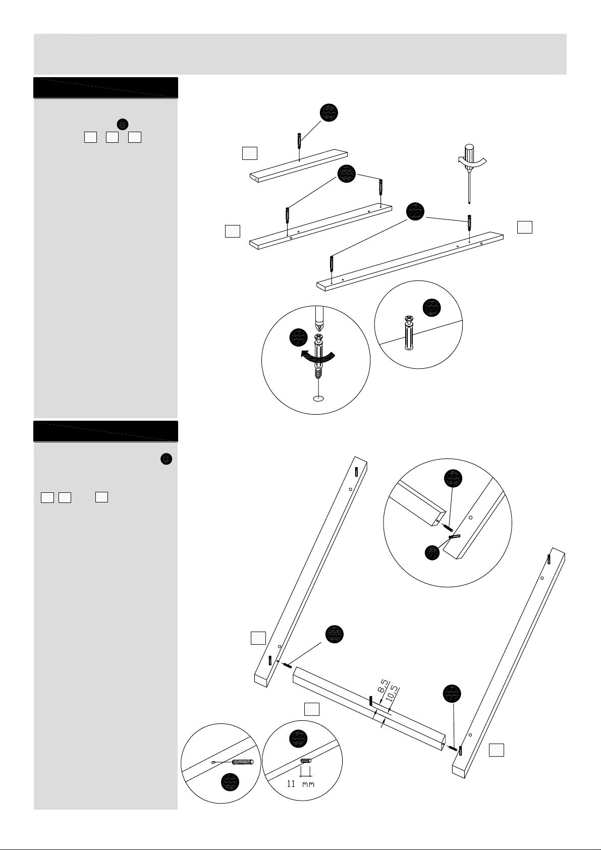
Assembly Instructions
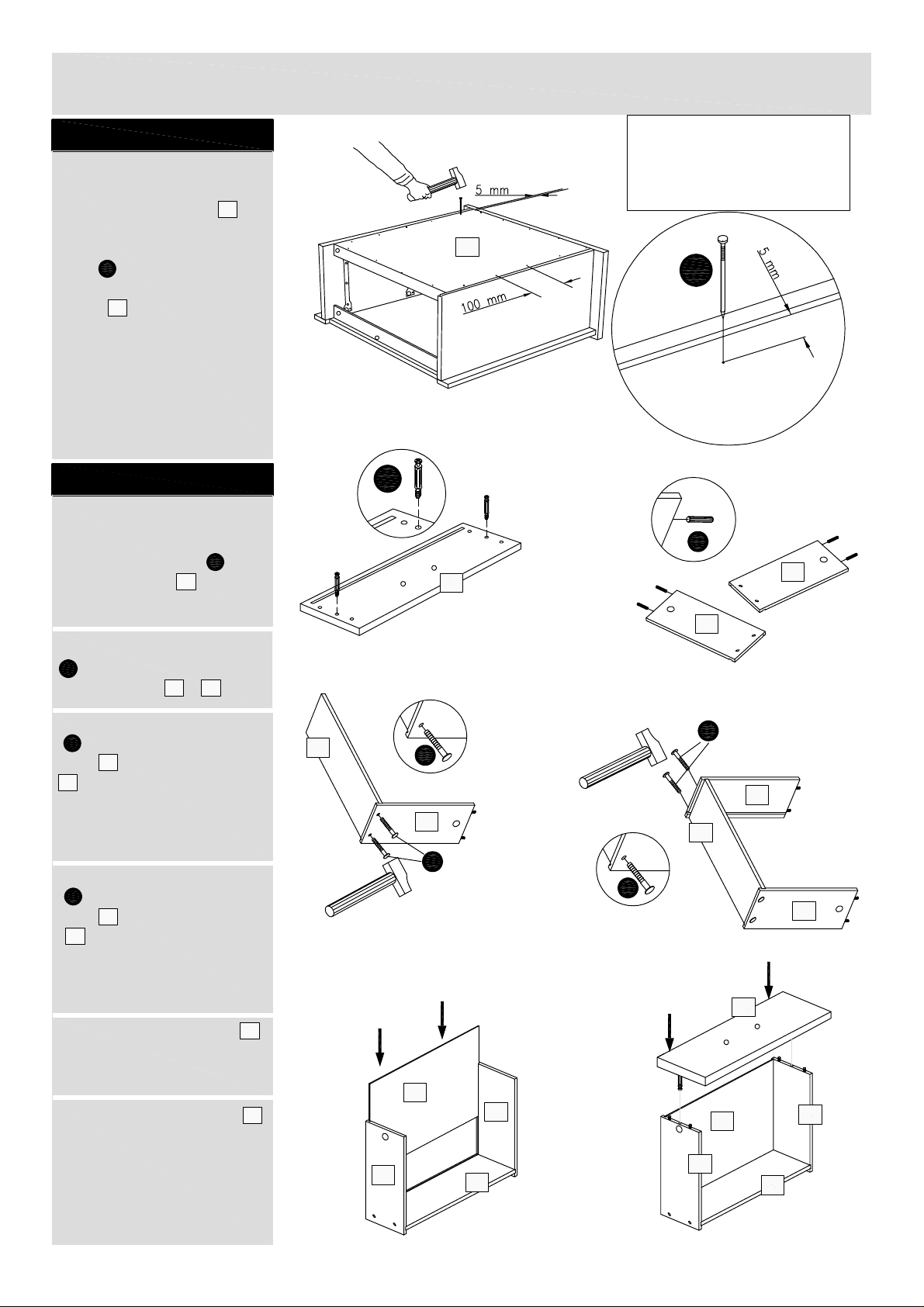
Step 4
Frame assembly
Insert screws in to the
frames , , .
7 8
E
9
E
9
E
E
7
8
E
E
Step 5
Insert wooden dowels
as shown, align correctly
and connect the frames
7 8
, and as shown
on the picture.
9
B
B
E
7
B
B
9
B
8
B
5
Page 7
Assembly Instructions
Step 6
2
Attaching the frame
Insert wooden dowels
B
into the edge of the
left and right side panels
2
1
, .
Align correctly and insert
large locking nuts into
left and right side panels
2
1
, and bottom front
support , place the
frame and turn locking
nuts clockwise to lock.
4
G
Step 7
Attaching top panel
B
8
4
9
1
G
B
B
7
5
G
G
Insert screws into the
drilled holes of the top
panel .
Insert wooden dowels
shown, align correctly and
insert large locking nuts
panels and , place
locking nuts clockwise to
lock.
3
into the top edges as
B
G
into left and right side
1
the top panel and turn
E
2
3
E
E
3
3
B
B
1
B
2
G
G
5
4
6
Page 8
Assembly Instructions
Step 8
Attaching back panel
Position back panel
in position on the back of
bedside chest. Position
D
nails 5 mm in from
side edge of the back
panel with distance
100 mm between each
other. Fix them using the
hammer.
6
Step 9
Step 9
Drawer assembly
a: Insert screws into
drawer front .
6
E
19
a:
E
19
Note: You must ensure
the bedside chest is
square before attaching
the back panel.
6
D
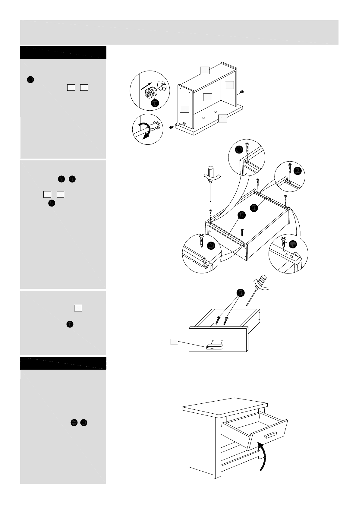
b:
C
12
b: Insert wooden dowels
C
into left and right
12
drawer sides , .
c: Insert plastic dowels
J
into left drawer
12
side and drawer back
18
and fix it together using
the hammer.
d: Insert plastic dowels
J
into right drawer
11
side and drawer back
18
and fix it together
using the hammer.
e: Slide drawer base
into the grooves.
f: Place drawer front
onto sides.
11
20
19
c:
18
e:
20
J
12
11
J
d:
11
18
J
J
12
19
f:
12
20
12
continued on next page
7
7
11
18
11
18
Page 9
Assembly Instructions
Step 9 - continued
Step 9 - continued
g: Align correctly and
insert small locking nuts
H
into left and right
12
12
11
M
N
drawer sides , and
turn them clockwise to
lock.
h: Position left and right
runners B , on
to left and right drawer
sides , , fix using
screws .
11
K
g:
18
11
H
12
20
h:
19
K
K
N
M
i: All drawers:
Attach handles
to drawer fronts
using screws .
Repeat assembly for
the remaining drawers.
15
S
Step 10
Inserting drawers
Insert the drawers
moving up and down as
shown and ensure that
wheels fit onto left and
L
right runners , .
R
15
i:
K
S
K
Check the gaps
between the drawers
and if they line up,
assembly is complete.
8
8
Page 10

Assembly Instructions
Step 11
Drawer runner adjustment
To move drawers up or
down: loosen screws as
shown and move runners
L
, up or down as
R
required.
Retighten screws and fix
the runners , using
screws 4.
R
Z
F
a:
F
L
b:
L
F
L
c:
F
L
d:
Z
4
Assembly is complete.
F
F
L
If you need help or have damaged or missing parts, call the Customer Helpline: 03456 400 800
Home Retail Group Plc, 489 - 499 Avebury Boulevard, Milton Keynes, MK9 2NW
9
Page 11

Wiltshire - 2 Door Wardrobe
Assembly Instructions
- Please keep for future reference
2387305
2466714
2473628
Dimensions
Width - 89cm
Depth - 52cm
Height- 184.5cm
Important
If you need help or have damaged or missing parts, call the
14-3E-221_01
– Please read these instructions fully before starting assembly
Customer Helpline:
03456 400 800
Issue 1 - 14/06/06
Page 12

Safety and Care Advice
Important – Please read these instructions fully before starting assembly
• Check you have all the
components and tools listed on
the following pages.
• Remove all fittings from the
plastic bags and separate them
into their groups.
• Keep children and animals
away from the work area, small
parts could choke if swallowed.
• Make sure you have enough
space to layout the parts before
starting.
Care and maintenance
• Only clean using a damp cloth
and mild detergent, do no use
bleach or abrasive cleaners.
• Do not stand or put weight on
the product, this could cause
damage.
• Assemble the item as close to
its final position (- in the same
room)as possible.
• Assemble on a soft level surface
to avoid damaging the unit or your
floor.
• Parts of the assembly will be
easier with 2 people.
• From time to time check that
there are no loose screws on
this unit.
• To reduce the
likelihood of
damaging your
product please
ensure that your
power drill is set
on a low torque
setting.
• This product should not be
discarded with household waste.
Take to your local authority
waste disposal centre.
Handy Hints
• Assemble all parts and bolts
loosely during assembly, only
once the product is complete
should you fully tighten bolts.
• Regularly check and ensure
that all bolts and fittings are
tightened properly.
1
Page 13

If you have damaged or missing commponents,
Components - Panels
call the
Please check you have all the panels listed below
Customer Helpline:
3
Top panel x 1 (89 x 52cm)
03456 400 800
Right side panel x 1
1
(49 x 182.2cm)
6
Back panel x 2
(38.5 x 174.1cm)
Left side panel x 1
2
(49 x 182.2cm)
7
Right hinge frame x 1
(5.3 x 182.2cm)
8
Left hinge frame x 1
(5.3 x 182.2cm)
Bottom plinth x 1
9
(74.9 x 2cm)
Bottom panel x 1
4
(75 x 48.6cm)
Handle x 2
15
(10.5 x 1.9cm)
Large horizontal partition
16
shelf x 1 (75 x 48.4cm)
Right door x 1
23
(37 x 170.6cm)
Left door x 1
25
(37 x 170.6cm)
2
Page 14

Components - Fittings
Please check you have all the fittings listed below
Note:
The quantities below are the correct amount to complete the assembly. In some cases more fittings may
be supplied than are required.
A
Feet x 4
E
Screw x 27
S
30mm Screw x 4
W
Door hinge x 6
Z
Hanger rail x 1
B
8/30mm Wooden dowel x 30
G
Large locking nut x 27
U
Hanger rail support x 2
X
Wall strap x 1
2
Z
14mm Screw x 2
D
Nail x 50
O
Underlay x 2
V
Hinge plates x 6
Y
13mm Screw x 1
3
Z
Door stop x 1
Tools required
Phillips screwdriver
(medium & large)
Flatblade screwdriver
(medium)
Ruler - Use this ruler to help correctly identify the screws
The screws length is measured from the head to the point (30mm screw shown)
Hammer
Ruler/tape
measure
3
Page 15

Assembly Instructions
Step 1
a: Preparation for the
attaching of horizontal
partition shelf and
bottom panel
Insert screws into the
drilled holes of the left and
right side panels and
2
, top panel and fix
them.
b: Attaching feet
Position plastic feet
to the left and right side
panels
below and fix them using
the hammer.
Step 2
E
1
3
A
and
2
from
A
1
b:
A
E
a:
E
E
2
1
E
3
E
E
Insert wooden dowels
into the bottom panel
and partition shelf and
place on left and right side
panels , .
Align correctly and insert
large locking nuts and
turn them clockwise to
lock.
2
1
B
4
16
G
B
B
B
16
2
G
G
B
1
G
B
G
4
B
4
Page 16

Assembly Instructions
Step 3
Frame assembly
Insert screws in to the
frames , , .
7 8
E
9
E
E
9
E
E
7
8
E
E
B
Step 4
Insert wooden dowels
as shown, align correctly
and connect the frames
7 8
, and as shown
on the picture.
9
B
B
B
7
B
E
B
9
8
5
Page 17

Assembly Instructions
Step 5
Attaching the frame
Insert wooden dowels
B
into the edge of the
left and right side panels
2
1
, .
Align correctly and insert
large locking nuts into
left and right side panels
2
1
, and bottom
panel , place the frame
and turn locking
nuts clockwise to lock.
4
G
Step 6
Attaching top panel
Insert wooden dowels
B
into the top edges as
shown, align correctly and
insert large locking nuts
into left and right side
G
panels and , place
the top panel and turn
locking nuts clockwise to
lock.
1
2
3
B
2
G
G
G
4
B
B
1
B
1
G
Step 7
Attaching back panels
With help, carrefully lay
wardrobe down
Position back panel
in position on the back of
wardrobe. Position nails
D
5 mm in from side edge
of the back panel with
distance 100 mm between
each other. Fix them using
the hammer.
6
6
B
2
G
B
3
D
6
6
4
Note: You must ensure
the wardrobe is
square before attaching
the back panels.
6
Page 18

Assembly Instructions
Step 8
a: Attaching hanger
rail
With help, carefully
stand wardrobe upright.
Warning:
The wardrobe
is heavy.
Lift with care.
Insert hanger rail
supports and place
the hanger rail .
b: Fitting door stop
Position door stop 3
onto the the bottom
panel , fix using
screws 2.
U
Z
Z
4
Z
b:
Z
a:
Z
U
2
3Z
Step 9
Fitting hinges to doors
Position 3 door hinges
into left and right doors
23
25
, , fix using supplied
screws.
W
Step 10
Attaching handles to
doors
Attach handles to
doors , using
screws .
23
S
15
25
25
23
W
23
S
15
7
Page 19

Assembly Instructions
Step 11
Fitting hinges to side
panels
Position 3 hinge plates
into left and right side
V
panels , . Small
arrow on the hinge plate
must point outwards. Fix
using supplied screws.
2
1
V
2
1
Step 12
Hanging doors
With help, slot door hinges
W
onto hinge plates
and click into position.
Repeat for left door.
V
Step 13
Hinge adjustment
To move doors up or
down, in or out, left or
right: loosen screws as
shown and move doors up
or down, in or out, left or
right as required.
23
W
Retighten screws.
8
Page 20

Assembly Instructions
Step 14
Fixing to wall
It is recomended that the
chest is fixed to a wall.
Mark fixing hole onto wall.
Drill a hole and insert a
suitable wall plug. Fix wall
strap using a screw
suitable for your wall.
With help, move wardrobe
into position.
X
Warning:
Before drilling,
check wall for
hidden pipes and
cables.
Warning:
The wardrobe
is heavy.
Lift with care.
X
Fix wall strap to top of
wardrobe using screw
and underlay .
Assembly is complete.
X
Y
O
Y
O
X
Note: Wall fixings are not
supplied with this unit.
The correct type of fixing must
be used for your wall, seek
professional advice if in doubt.
If you need help or have damaged or missing parts, call the Customer Helpline: 03456 400 800
Home Retail Group Plc, 489 - 499 Avebury Boulevard, Milton Keynes, MK9 2NW
9
Page 21

Wiltshire - Chest of 5 Drawers
Assembly Instructions
- Please keep for future reference
2307189
2457235
2584902
Dimensions
Width - 89cm
Depth - 42.5cm
Height- 110.1cm
Important
If you need help or have damaged or missing parts, call the
14-3E-219_01
– Please read these instructions fully before starting assembly
Customer Helpline:
03456 400 800
Issue 1 - 14/06/06
Page 22

Safety and Care Advice
Important – Please read these instructions fully before starting assembly
• Check you have all the
components and tools listed on
the following pages.
• Remove all fittings from the
plastic bags and separate them
into their groups.
• Keep children and animals
away from the work area, small
parts could choke if swallowed.
• Make sure you have enough
space to layout the parts before
starting.
Care and maintenance
• Only clean using a damp cloth
and mild detergent, do no use
bleach or abrasive cleaners.
• Do not stand or put weight on
the product, this could cause
damage.
• Assemble the item as close to
its final position (- in the same
room)as possible.
• Assemble on a soft level surface
to avoid damaging the unit or your
floor.
• Parts of the assembly will be
easier with 2 people.
• From time to time check that
there are no loose screws on
this unit.
• To reduce the
likelihood of
damaging your
product please
ensure that your
power drill is set
on a low torque
setting.
• This product should not be
discarded with household waste.
Take to your local authority
waste disposal centre.
Handy Hints
• Assemble all parts and bolts
loosely during assembly, only
once the product is complete
should you fully tighten bolts.
• Regularly check and ensure
that all bolts and fittings are
tightened properly.
1
Page 23

If you have damaged or missing commponents,
Components - Panels
call the
Please check you have all the panels listed below
Customer Helpline:
3
Top panel x 1 (89 x 42.5cm)
Bottom front support x 1
4
(75 x 7.1cm)
03456 400 800
Right side panel x 1
1
(39.5 x 107.8cm)
6 Back panel x 1
(38.5 x 99.7cm)
Left side panel x 1
2
(39.5 x 107.8cm)
7
Right hinge frame x 1
(5.3 x 107.8cm)
8
Left hinge frame x 1
(5.3 x 107.8cm)
Bottom back support x 1
5
(75 x 7.1cm)
Bottom plinth x 1
9
(74.9 x 2cm)
10
Large drawer front x 5
(74.3 x 19cm)
Right drawer side x 5
11
(35 x 13cm)
Large drawer base x 5
14
(71 x 33.9cm)
12
15
Left drawer side x 5
(35 x 13cm)
Handle x 10
(10.5 x 1.9cm)
Large drawer back x 5
13
(70.6 x 13cm)
2
Page 24

Components - Fittings
Please check you have all the fittings listed below
Note:
The quantities below are the correct amount to complete the assembly. In some cases more fittings may
be supplied than are required.
A
Feet x 4
D
Nail x 30
G
Large locking nut x 15
K
20mm Screw x 20
N
Runner right B x 5
B C
8/30mm Wooden dowel x 20
E F
Screw x 25
H
Small locking nut x 10
L
Runner left A x 5
O
Underlay x 2
6/30mm Wooden dowel x 20
9mm Screw x 20
J
Plastic dowel x 20
M
Runner left B x 5
P
Drawer base support x 10
R
Runner right A x 5
2
U
10mm Screw x 10
Tools required
X
Wall strap x 1
Phillips screwdriver
(medium & large)
Flatblade screwdriver
(medium)
S
30mm Screw x 20
Y
13mm Screw x 1
Ruler - Use this ruler to help correctly identify the screws
2
T
Reinforcing metal strap x 5
Z
4
12mm Screw x 10
Hammer
Ruler/tape
measure
The screws length is measured from the head to the point (30mm screw shown)
3
Page 25

Assembly Instructions
Step 1
Attaching runners
a: Position left runners
L
and right runners A
A
R
on to the drilled holes
of the left and right side
panels and .
Fix through holes shown
using screws .
b: Attaching feet
Position plastic feet
to the left and right side
panels
below and fix them using
the hammer.
1
1
and
Step 2
Preparation for the
attaching of bottom
supports
Insert screws into
the drilled holes of the
left and right side
panels
1
2
F
2
E
2
and .
A
from
A
b:
a:
F
L
2
F
A
F
F
L
E
E
2
1
F
1
R
R
E
Step 3
Attaching the bottom
supports
Insert wooden dowels
B
into the bottom front
and back supports
5
and and place on left
and right side panels
2
, . Align correctly and
insert large locking
G
nuts into the bottom
front and back supports
4
and and turn them
clockwise to lock.
5
4
1
G
2
B
B
1
B
4
G
G
5
B
4
Page 26

Assembly Instructions
Step 4
Frame assembly
Insert screws in to the
frames , , .
7 8
E
9
E
9
7
E
E
E
8
E
E
E
Step 5
Insert wooden dowels
as shown, align correctly
and connect the frames
7 8
, and as shown
on the picture.
9
B
B
E
7
B
B
9
B
8
B
5
Page 27

Assembly Instructions
Step 6
Attaching the frame
Insert wooden dowels
B
into the edge of the
left and right side panels
2
1
, .
Align correctly and insert
large locking nuts into
left and right side panels
2
1
, and place the
frame and turn locking
nuts clockwise to lock.
G
Step 7
Attaching top panel
Insert screws into the
drilled holes of the top
panel .
Insert wooden dowels
into the top edges as
B
shown, align correctly and
insert large locking nuts
G
into left and right side
panels and , place
the top panel and turn
locking nuts clockwise to
lock.
3
1
E
2
3
2
G
1
B
B
B
5
8
4
9
7
B
G
G
E
E
3
3
B
B
1
B
2
5
G
G
4
6
Page 28

Assembly Instructions
Step 8
Attaching back panel
Position back panel
in position on the back of
bedside chest. Position
D
nails 5 mm in from
side edge of the back
panel with distance
100 mm between each
other. Fix them using the
hammer.
6
6
Step 9
Drawer assembly
a: Insert screws into
drawer front .
E
10
a:
E
Note: You must ensure
the chest is square
before attaching
the back panel.
6
D
10
b:
C
b: Insert wooden dowels
into left and right
C
12
drawer sides , .
c: Insert plastic dowels
J
into left drawer
12
side and drawer back
13
and fix it together
using the hammer.
d: Insert plastic dowels
J
into right drawer
11
side and drawer back
13
and fix it together
using the hammer.
e: Slide large or small
drawer base into the
grooves.
11
14
c:
13
e:
12
12
11
J
J
J
14
12
d:
11
J
13
12
10
f:
f: Place large or small
drawer front onto
sides.
continued on next page
7
10
11
13
11
13
14
12
Page 29

Assembly Instructions
Step 9 - continued
g: Align correctly and
insert small locking nuts
H
into left and right
12
12
11
M
N
TUT
2
drawer sides , and
turn them clockwise to
lock.
h: Position left and right
runners B , on
to left and right drawer
sides , , fix using
screws .
i: Large drawers only:
Position the reinforcing
metal strap onto the
large drawers as shown.
Fix using supplied screws
.
11
K
2
g:
U
i:
2
13
11
14
H
T
12
10
h:
K
2
K
K
N
M
K
j: Large drawers only:
Position 2 drawer base
supports onto the large
drawers as shown. Fix
using supplied screw.
k: All drawers:
Attach handles
to drawer fronts
using screws .
Repeat assembly for
the remaining drawers.
P
15
S
k:
S S
15
U
j:
2
P
S
P
15
8
Page 30

Assembly Instructions
Step 10
Fixing to wall
It is recomended that the
chest is fixed to a wall.
Poke wall strap
through the hole in the
back panel and fix it to top
panel underneath using
screw and underlay .
Mark fixing hole onto wall.
Drill a hole and insert a
suitable wall plug. Fix wall
strap using a screw
suitable for your wall.
With help, move chest
into position.
Y
X
Warning:
Before drilling,
check wall for
hidden pipes and
cables.
X
O
Note: Wall fixings are not
supplied with this unit.
The correct type of fixing must
X
be used for your wall, seek
professional advice if in doubt.
X
Warning:
The chest
is heavy.
Lift with care.
Step 11
Inserting drawers
Insert the drawers
moving up and down as
shown and ensure that
wheels fit onto left and
R
right runners , .
L
X
O
Y
R
L
Check the gaps
between the drawers
and if they line up,
assembly is complete.
9
Page 31

Assembly Instructions
Step 12
Drawer runner adjustment
To move drawers up or
down: loosen screws as
shown and move runners
L
, up or down as
R
required.
Retighten screws and fix
the runners , using
screws 4 .
R
Z
F
F
L
a:
L
F
Assembly is complete.
b:
F
L
c:
F
L
F
d:
Z
4
L
If you need help or have damaged or missing parts, call the Customer Helpline: 03456 400 800
Home Retail Group Plc, 489 - 499 Avebury Boulevard, Milton Keynes, MK9 2NW
10
 Loading...