

Page 1
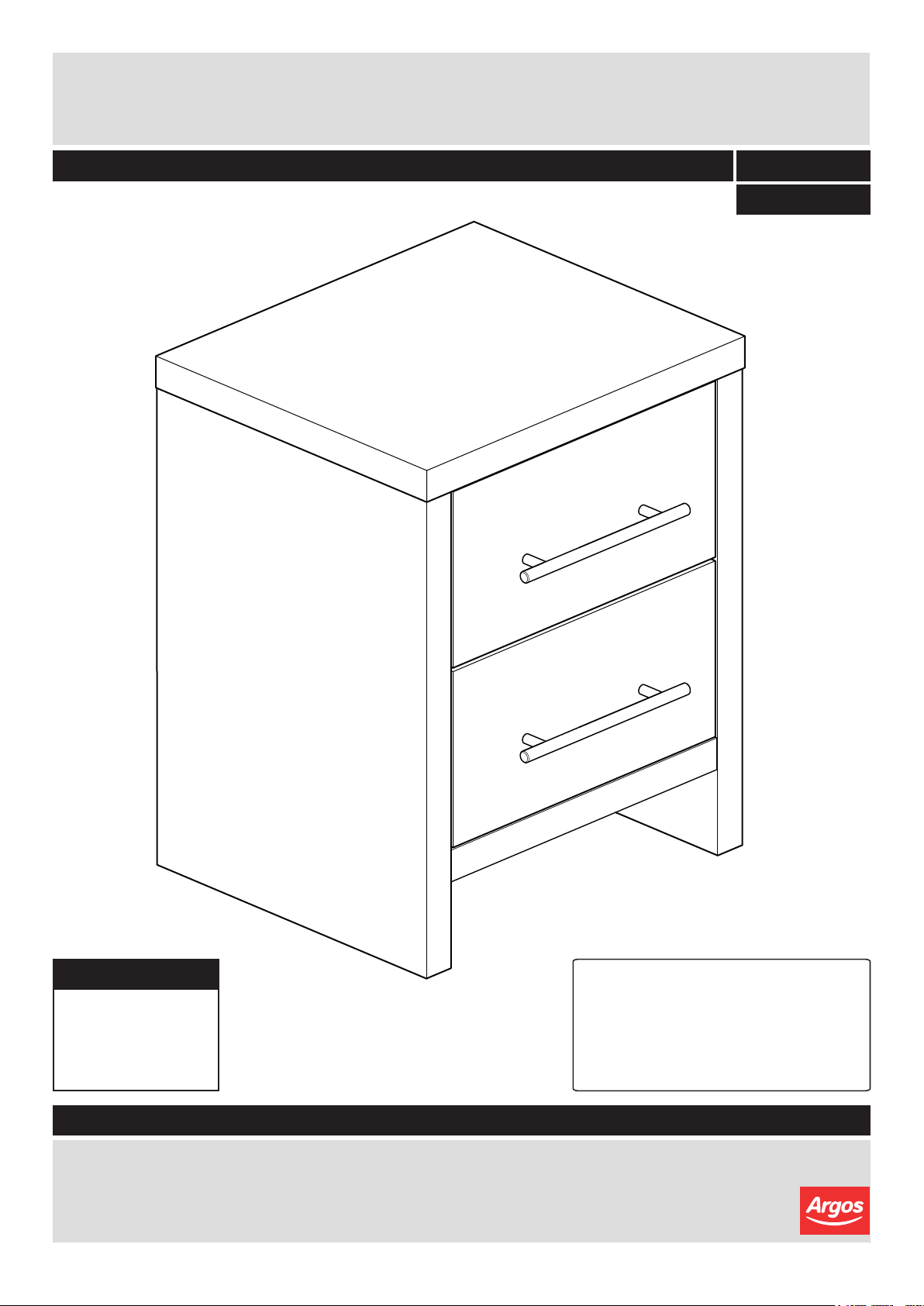
Washington - 02BS
DR82534
Assembly Instructions - Please keep for future reference
392/3342
427/1433
Dimensions
Width - 43.8cm
Depth - 37.3cm
Height - 54.7cm
392/3342 SMOKEY OAK
427/1433 WARM OAK
Tip : To prevent damage,
we recommend that you
build your unit on the
carton(s) it was packed in.
Important – Please read these instructions fully before starting assembly
If you need help or have damaged or missing parts, please visit: www.argos-support.co.uk
or email: Help@ClickSpares.co.uk (quoting your original order number)
Alternatively, call the Spares Helpline on: 0370 112 1928
For any other queries please contact the Customer Helpline on: 0345 640 2020
Issue 1 - 02/07/15
Page 2
Safety and Care Advice
Important – Please read these instructions fully before starting assembly
• Check you have all the
components and tools listed
on the following pages.
• Remove all fittings from the
plastic bags and separate them
into their groups.
• Keep children and animals
away from the work area, small
parts could choke if swallowed.
• Make sure you have enough
space to layout the parts before
starting.
• Do not stand or put weight on
the product, this could cause
damage.
• Assemble the item as close
to its final position (in the same
room) as possible.
• Assemble on a soft level
surface to avoid damaging the
unit or your floor.
• Parts of the assembly will be
easier with 2 people.
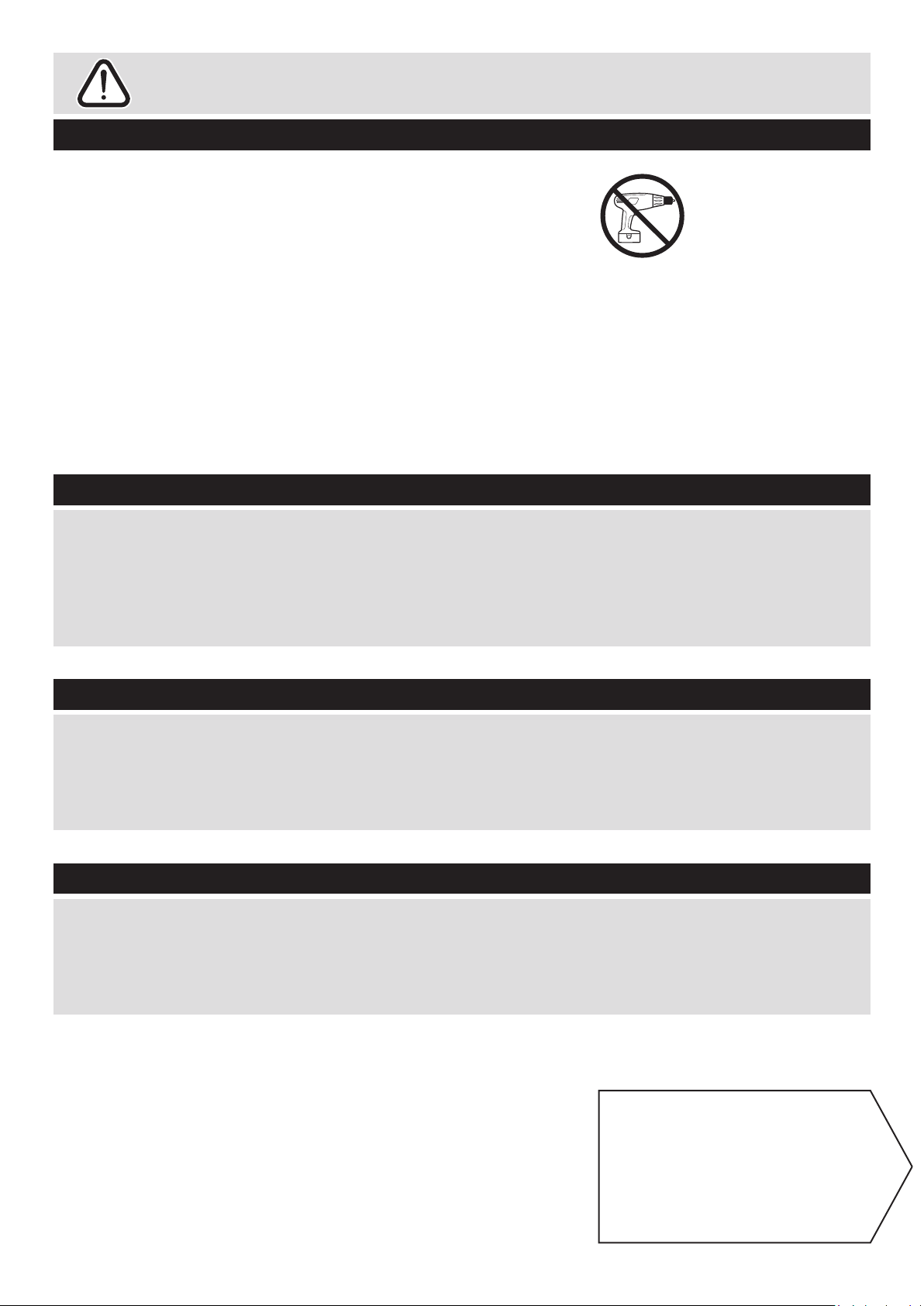
• We do not
recommend the
use of power drill/
drivers for
inserting screws,
as this could damage the unit.
Only use hand screwdrivers.
• Dispose of all packaging
carefully and responsibly.
Glue safety - Take care when using glue, please follow the advice below•
Skin contact: Remove
contamination by washing with
soap and water. This procedure
should also be followed prior to
eating and drinking.
Eye contact: Rinse immediately
with clean water for 15 minutes
and seek medical advice.
If swallowed: Seek medical
advice immediately.
Care and maintenance
• Only clean using a damp cloth
and mild detergent, do no use
bleach or abrasive cleaners.
Handy Hints
• Assemble all parts and bolts
loosely during assembly, only
once the product is complete
should you fully tighten the bolts
• From time to time check that
there are no loose screws on
this unit.
• Regularly check and ensure
that all bolts and fi ttings are
tightend properly.
• This product should not be
discarded with household waste.
Take to your local authority
waste disposal centre.
•
Note: if required the next
page can be cut out and used
as reference throughout the
assembly. Keep this page with
these instructions for future
reference.
1
Page 3
For damaged or missing parts, please visit:
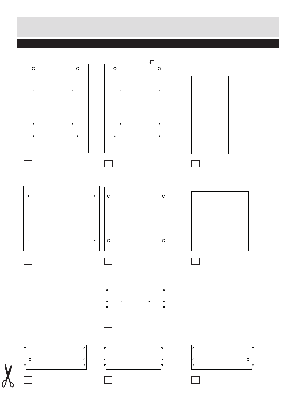
Components - Panels
www.argos-support.co.uk or email: Help@ClickSpares.co.uk
Please check you have all the panels listed below
ID-hole
Left side
1
(37.1 x 51.3cm)
P2018
Top
4
(43.8 x 37.3cm)
P1830
Right side
2
(37.1 x 51.3cm)
P2093
Bottom
5
(36.7 x 37cm)
P1831
Foldy back
3
(42.9 x 44.9cm)
B03609
Drawer bottom x 2
6
(32.8 x 34.4cm)
BO3607
Left drawer x 2
8
(35 x 14cm)
LA1614
Drawer front x 2
7
(36.1 x 18.9cm)
P4648
Drawer back x 2
9
(317 x 14cm)
LA1618
Right drawer x 2
10
(35 x 14cm)
LA1615
2
Page 4
For damaged or missing parts, please visit:
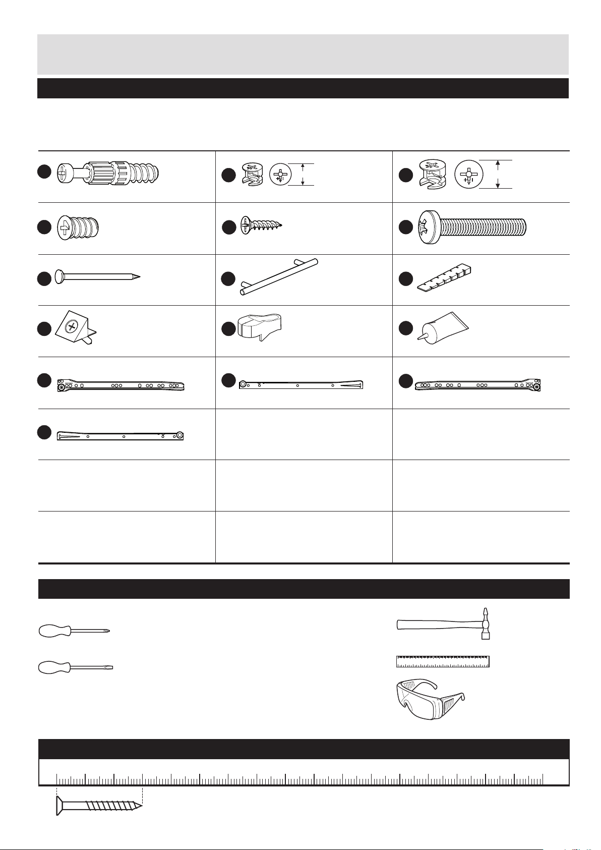
Components - Fittings
www.argos-support.co.uk or email: Help@ClickSpares.co.uk
Please check you have all the fittings listed below
Note: The quantities below are the correct amount to complete the assembly. In some cases more fittings
may be supplied than are required.
FK1011
A
Locking screw x 12 (5x24mm)
FK1301
D
Fixing screw drawer x 24 (6.3x10mm)
FK1515
Nail x 12
FK1250
Drawer base support x 4
PM1515 LA
Runner left part A x 2
PM1515 RB
P
12mm
Locking nut x 4 (12x10mm)
E
Screw x 28 (3x15mm)
Drawer handle x 2
FK1415
KJ
Nail holder x 1
PM1515 LB
NM
Runner left part B x 2
FK1010
FK1311
GR1855
CB
15mm
Large locking nut x 8 (15x12mm)
F
Screw x 4 (4x25mm)
IHG
Peg, brown x 1
FA1510
L
Glue x 1
PM1515 RA
O
Runner right part A x 2
FK1012
FK1985
FK1234
Runner right part B x 2
Tools required
Phillips screwdriver
(medium & large)
Flatblade screwdriver
(medium)
0102030405060708090 100 110 120 130 140 150
0123456
Eye protection
(when using a
hammer or glue)
Small
hammer
Ruler/tape
measure
Ruler - Use this ruler to help correctly identify the screws
0 5 10 15 20 25 30 35 40 45 50 55 60 65 70 75 80 85 90 95 100
The screws length is measured from the head to the point (30mm screw shown).
3
105
110 115 120 125 130 135 140 145 150 155 160 165 170
Page 5

Assembly Instructions
Step 1
a:
a: Screw 24mm locking
screw A into left side 1.
C
Note: Insert 24mm locking
screw A as far as shown.
Do not over tighten.
Insert large locking nuts C
into left side 1.
Make sure the ‘arrow’ on
locking nuts C points
towards the hole in the
edge of left side 1.
C
A
1
A
Finished
front edge
C
A
Attaching runners
b: Fix runner left part A M
on left side 1 as shown
usesing fixing screw
drawer D into left side 1.
Note: look carreful for the
right postion.
Insert 15mm screw E
as shown into left side 1
to fix runner left part A M.
b:
Finished
front edge
D
D
M
D
M
E E E
D D
M
D
1
4
Page 6

Assembly Instructions
Step 2
a:
a: Screw 24mm locking
screw A into right side 2.
Note: Insert 24mm locking
screw A as far as shown.
Do not over tighten.
C
ID-hole
C
Finished
front edge
A
Insert large locking nuts C
into right side 2.
Make sure the ‘arrow’ on
locking nuts C points
towards the hole in the
edge of right side 2.
Attaching runners
b: Fix runner right part A O
on right side 2 as shown
usesing fixing screw
drawer D into right side 2.
Note: look carreful for the
right postion.
b:
2
A
C
A
D
D
O
D
O
Finished
front edge
D
Insert 15mm screw E
as shown into right side 2
to fix runner right part A O.
5
E E E
D D
O
Page 7

Assembly Instructions
Step 3
Screw 24mm locking
screw A into top 4.
Note: Insert 24mm locking
screw A as far as shown.
Do not over tighten.
Step 4
A
A
A
4
A
Finished
front edge
A
C
Insert large locking nuts C
into bottom 5.
Make sure the ‘arrow’ on
locking nuts C points
towards the hole in the
edge of bottom 5.
Step 5
Attaching panels
Position left side 1 and
right side 2 onto bottom
5.
Use a screwdriver to turn
locking nuts C clockwise
to lock.
C
5
C
C
5
2
I
1
C
Finished
front edge
Finished
front edge
6
Page 8

Assembly Instructions
Step 6
Attaching panels
Position top 4 onto left
side 1 and right side 2.
Use a screwdriver to turn
locking nuts C clockwise
to lock.
4
1
Step 7
Fitting back panel
Attach foldy back 3 to the
back with the coloured
surface facing the inside
using nails G.
Use nail holder K to hold
the nails G vertical and at
correct distance as you
secure the foldy back 3.
Nails G should be spaced
about 150mm apart.
Finished
front edge
G
2
C
G
3
G
G
K
2
5
G
5
Important:
Furniture MUST
be ‘square’ when
back is attached.
G
K
7
Page 9

Assembly Instructions
Step 8
2x
Preparing drawer
Insert locking nuts B into
left drawer side 8 and
right drawer side 0.
L
L
10
Make sure the ‘arrow’ on
locking nuts B points
towards the hole in the
edge of 8 and 0.
Put drop of glue Q into the
3 holes of left drawer side
8 and right drawer side 0.
Attach left drawer side 8
and right drawer side 0
onto drawer back 9.
Insert drawer bottom 6.
Step 9
Screw 24mm locking
screw A into drawer front
7.
2x
9
B
8
B
6
B
A
L
Note: Insert 24mm locking
screw A as far as shown.
Do not over tighten.
A
7
A
8
Page 10

Assembly Instructions
Step 10
Position drawer front 7
onto drawer.
Use a screwdriver to turn
locking nuts B clockwise
to lock.
Note: look carefully to the
positions of drawer front 7.
Fix drawer handle H onto
drawer front 7 using
screw F.
Step 11
a: Turn over drawer.
Fix runner left part B N
on left drawer side 8 as
shown using screw E.
2x
a:
2x
H
7
F
B
N
F
8
6
10
P
6
9
E
Fix runner right part B P
on right drawer side 0 as
shown using screw E.
b: Fix runner left part B N
and runner right part B P
using screw E.
Slide drawer base support
J in corner as shown and
fix them, using the attached
screw.
b:
2x
10
8
E
N
E
E
J
6
E
E
8
9
P
J
E
E
11
9
J
9
Page 11

Assembly Instructions
Step 12
Inserting drawers
as shown.
For adjusting the drawers
see ‘adjustment’ on page
‘drawer adjustment’.
1
4
7
7
Step 13
Use peg I to square your
furniture. Knock peg I in,
as far as you require, under
the end of the side of the
forniture. Then snap off
flush with the side.
Assembly is complete.
I
I
!
I
If you need help or have damaged or missing parts, call the Customer Helpline:
Argos 03456 400 800
10
Page 12

A Guide to - Drawer adjustment
Adjustment
Note: Each drawer can be
adjust for approximately
1mm up or down on each
site of the drawer.
Remove drawer, adjust the
wheel from runner left
part A and runner right part
A as shown.
Insert drawer.
Repeat above steps until
the desired result is
achieved.
M
Runner left part A x 2
+1 mm
O
Runner right part A x 2
-1 mm
0
11
 Loading...