

Argos TX-0109 ASSEMBLY INSTRUCTIONS
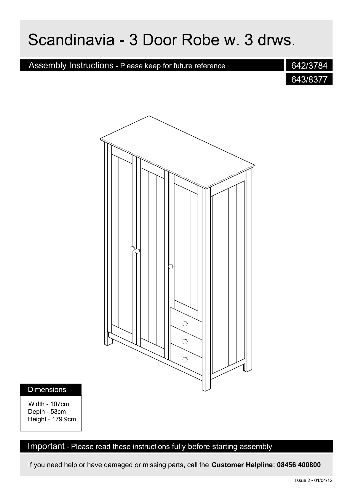
Scandinavia - 3 Door Robe w
. 3 drws
.
A
ssembly Instructi
on
s
- Please k
eep for future reference
642/3784
643/8377
Dimension
Width - 107cm
Depth - 53c
Height -
Import
s
m
179.9cm
- Please r
an
t
ead these instructions
If you need help or have dam
fully before starting assembly
aged or missing parts, call the
Customer Helpline: 08456 400800
Issue 2 - 01/04/12
!
Important
S
a
f
e
t
-
Please r
y
and
ead these instructions fully before starting assembl
C
a
r
e
A
d
v
i
c
e
y
Check you have all t
com
ponents and tools listed
pages 2
Remove all fittings from t
plastic bags
into their gr
Keep children
away from the work area, small
parts could choke if swallowed
Make sure you have enough
space to layou
starting
Care
Only clean using a damp clot
and mild detergen
bleach or abrasive cl
and 3
.
and s
oups.
and animal
t the parts before
.
and maint
he
on
he
eparate the
s
enance
t, do no us
eaners
m
.
e
.
Do not stand on
the pr
oduct, this could
cause dam
Assemble the item as clos
to its final position (in the same
room) as possible.
Assemble on a soft leve
surface to avoid damaging the
un
it or your floor
Parts of the assembly will be
easier with 2
From time to time check tha
h
here are no loose screws
t
this uni
age
t.
.
.
people
.
l
e
on
t
We do no
use of powe
dr
inserting screws
as this could damage the unit.
Only use
Dispose of all packaging
carefully
This product should not be
discar
waste. Take to your loca
authority waste disposal centre
ded with
recomm
ill/drivers
hand screwdrivers
and res
ponsibly.
household
t
end the
r
for
l
,
.
.
Note:
if r
equired the nex
page can be cut out and used
as reference throughou
assembly. K
these instructions for future
reference.
1
eep this page wit
t
t t
he
h
If you have damaged or missing components
C
o
m
ponen
t
s
-
P
ane
l
s
call the
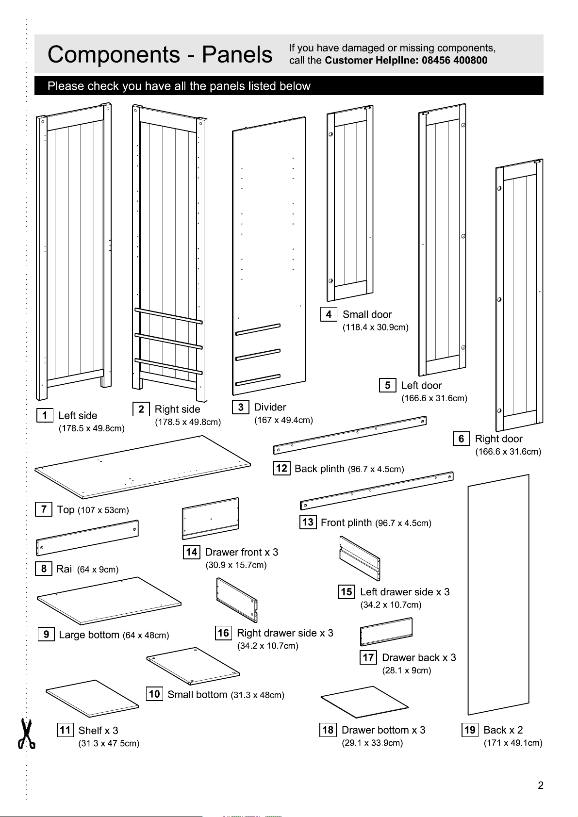
Please check you have all the panels listed below
Customer Helpline: 08456 400800
4
Small
doo
r
(
118.4 x 30.9cm
)
,
1
Left side
(
178.5 x 49.8cm
7
8
9
(
107 x 53cm
Top
Rail
(64 x 9cm)
Large bottom
2
Right side
(
)
)
(64 x 48cm)
178.5 x 49.8cm
)
14
Drawer front x
(30.9 x 15.7cm)
16
Divider
3
(
167 x 49.4cm
12
3
Right drawer side x
(34.2 x 10.7cm)
)
Back plinth
13
Front plinth
(96.7 x 4.5cm)
15
Left drawer side x 3
(34.2 x 10.7cm)
3
5
Left
(
166.6 x 31.6cm
(96.7 x 4.5cm)
17
Drawer back x 3
(28.1 x 9cm)
doo
r
)
6
Right doo
(
166.6 x 31.6cm
r
)
11
Shelf x 3
(31.3 x 47.5cm)
10
Small bottom
(31.3 x 48cm)
Drawer bottom x 3
18
(29.1 x 33.9cm)
Back x 2
19
(
171 x 49.1cm
)
2
C
o
m
ponen
t
s
-
F
i
tt
i
ng
s
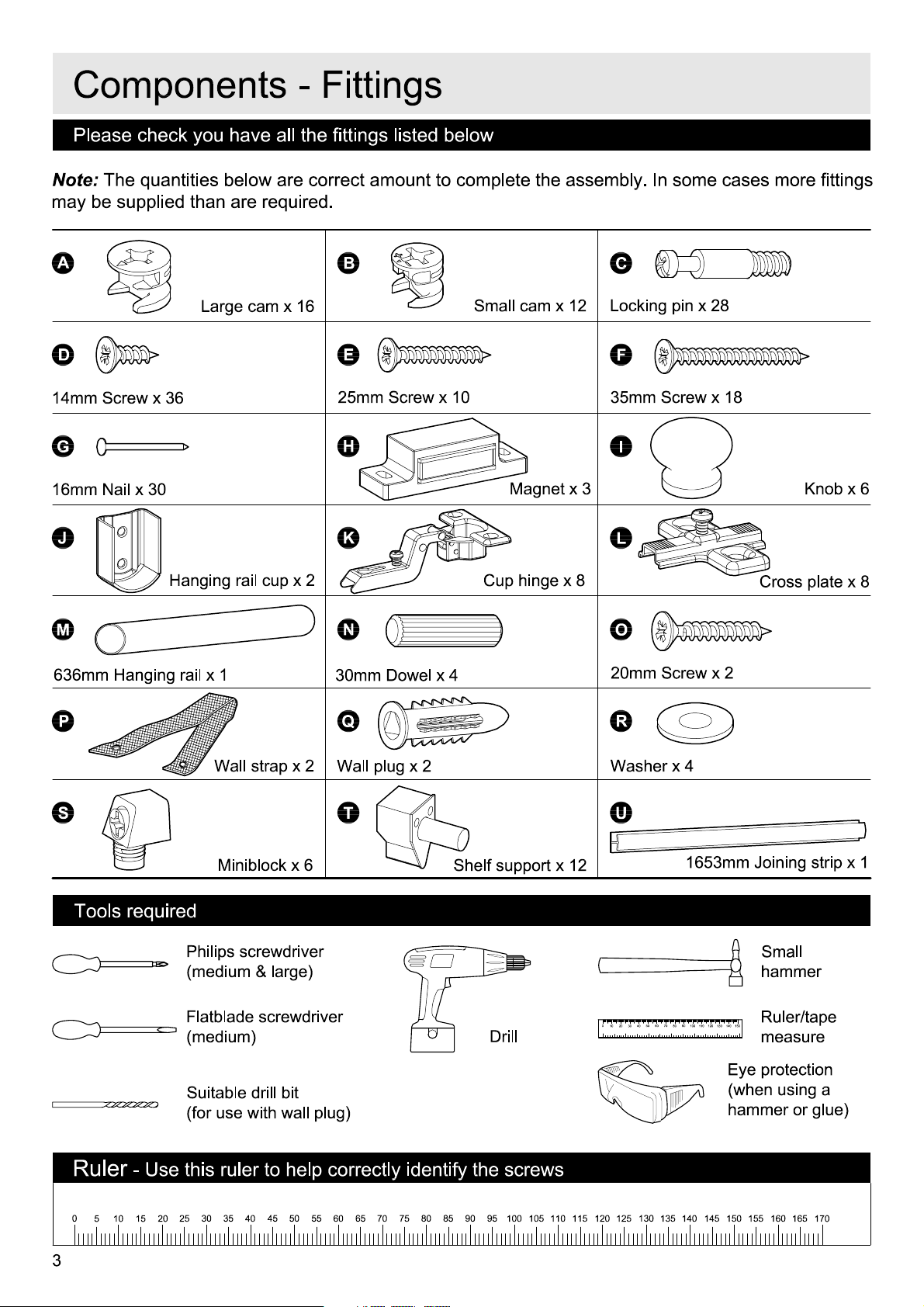
Please check you have all the fittings listed belo
Note:
The quantities below are correct am
may be s
A
D
14mm Screw x
G
16mm Nail x
J
upplied than are r
Large cam x 16
36
30
H
anging rail cup x
equired.
B
E
25mm Screw x
H
K
2
oun
t to complete the assembly
w
Small cam x
10
M
Cup hi
12
agnet x 3
nge x 8
. In some cases more fittings
C
Locking pin x
F
35mm Screw x
I
L
28
18
K
Cross plate x
nob x 6
8
M
636mm Hanging rail x 1
P
Wall strap x
S
Miniblock x
Tools requir
ed
Philips screwdrive
(medium & large
Flatblade screwdrive
(medium)
Suitable drill bit
(for use with wall plug
N
30mm Dowel x
Q
2
Wall plug x 2
T
6
r
)
r
)
4
Shelf support
Drill
x
O
20mm Screw x
R
Washer x 4
U
12
0
40
30
20
10
2
1653mm Joining strip x 1
Sma
hamme
70
50
60
8090100 110
120
150
130
140
Ruler/tape
measur
Eye protection
(when using
ha
mmer or glue)
ll
r
e
a
Ruler
0
3
- Use this ruler to help correctly identify the screws
55
35
30
5
10
25
15
20
50
45
40
65
60
75
70
9080
85 95
100
105
110
115 125
120
130
135
145 155 165
140
150
160
170
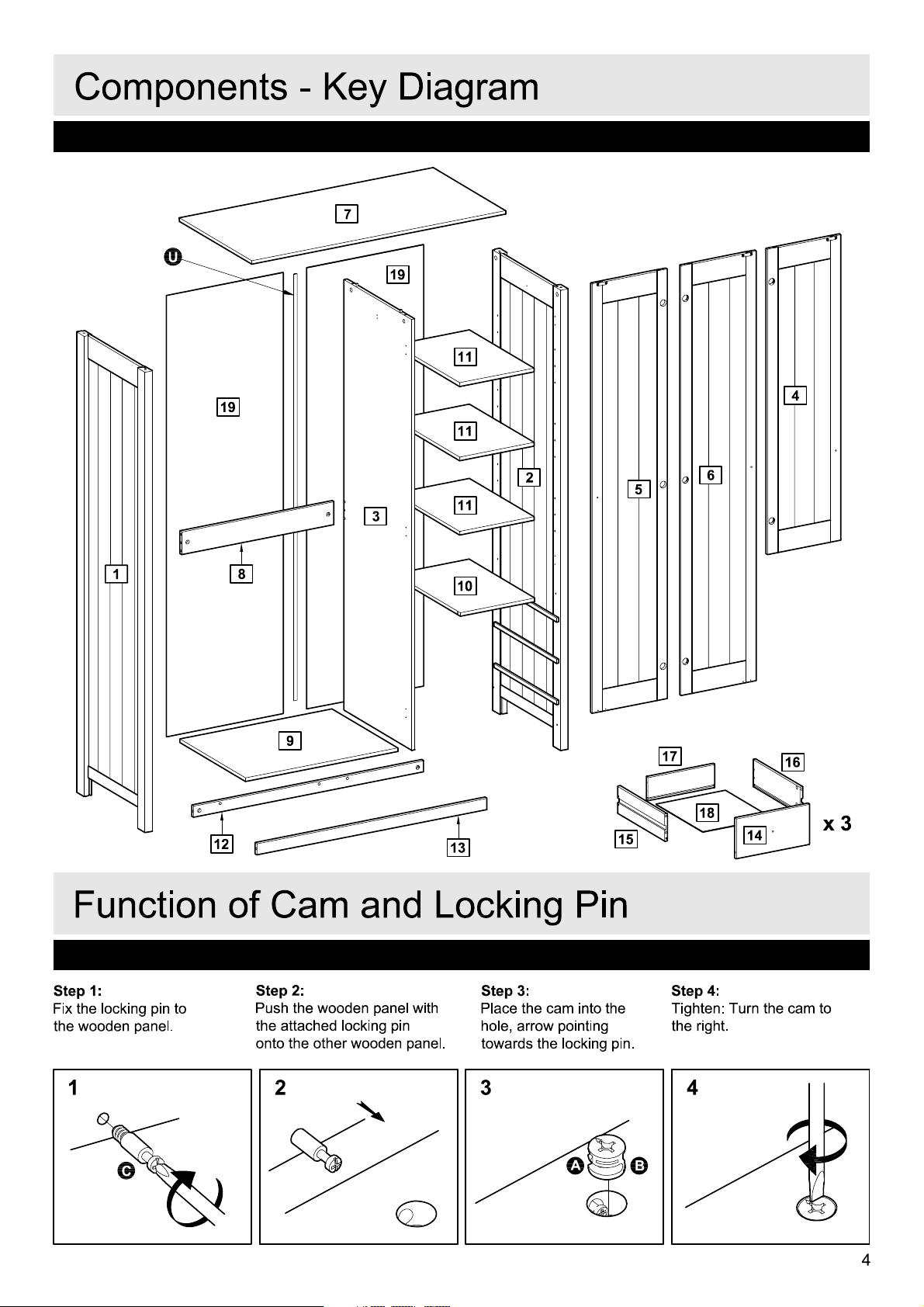
C
o
m
ponen
U
t
s
-
K
e
7
y
19
D
i
ag
11
r
a
m
14
4
16
x 3
19
11
2
3
1
8
9
12
11
10
13
5
15
6
17
18
F
un
c
t
i
on
Step 1
:
Fix the locking pin to
the wooden panel.
1
C
o
f
C
a
m
and
Step 2
:
Push the wooden panel with
the attac
onto the other wooden panel.
hed locking pin
2
Lo
ck
i
ng
Step 3
:
Place the cam into t
hole, arrow pointing
towards the locking pin
3
P
A
i
n
he
Step 4
:
Tighten: Turn the cam to
t
he righ
t.
.
4
B
4

A
ss
e
m
b
l
y
I
n
s
t
r
u
c
t
i
on
s
Step 1
M
ounting the cross
plates to the sides
Fix the cross plates
the sides
the screws
holes indicated.
It is important that the
cross plates are placed
exactly as shown
The short
cross plates must poin
towards the front edge of
the sides
1
&
E
end of the
.
.
L
2
using
into the
.
to
t
2
Side, righ
t
E
L
Fron
E
L
E
t
E
Long end
1
Side, lef
t
L
Short end
Fron
t
E
L
E
L
Fron
t
L
5
A
ss
e
m
b
l
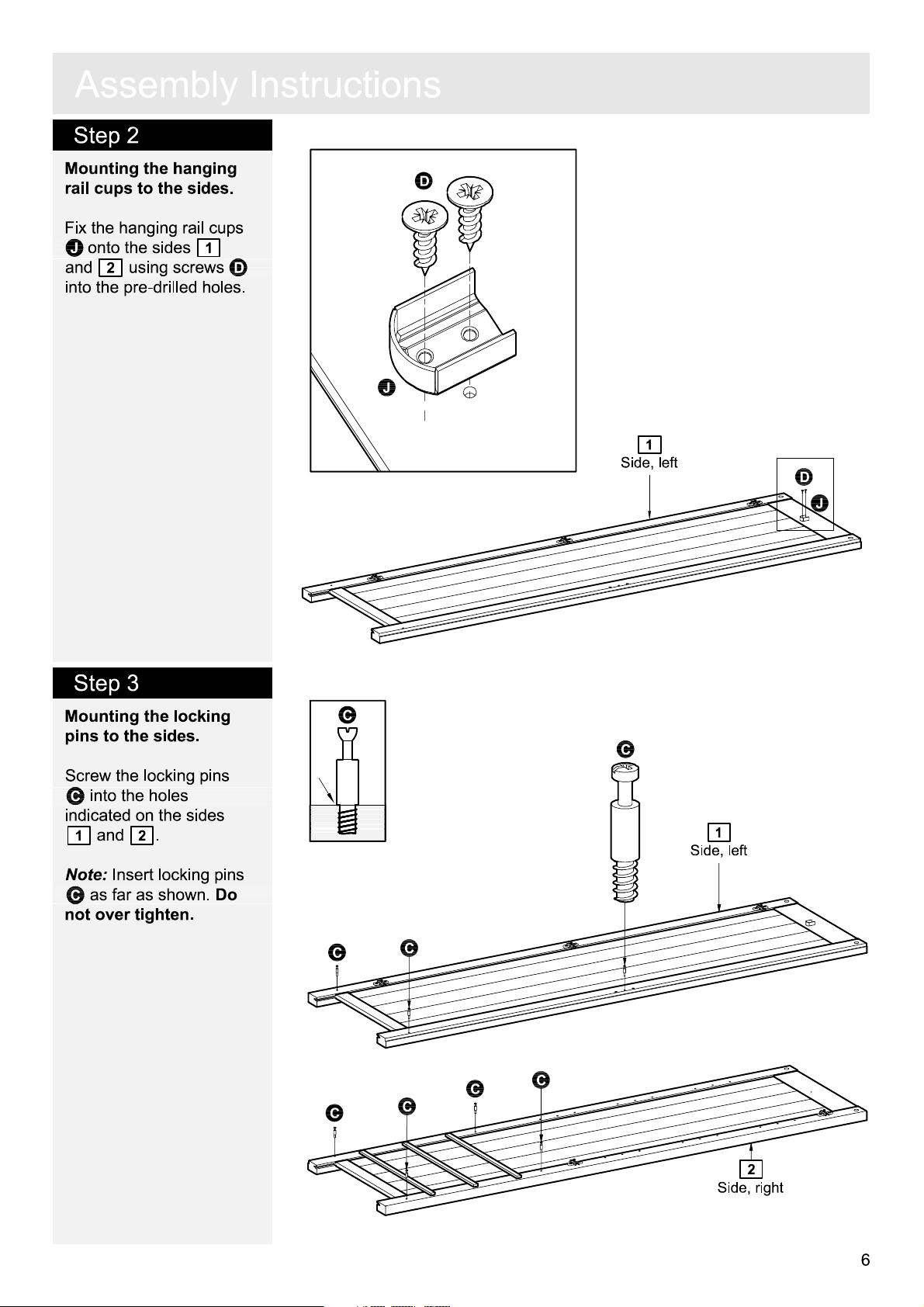
Step 2
M
ounting the
rail cups to the sides.
hanging
y
I
n
s
t
r
u
c
t
i
on
s
D
Fix the hanging rail cups
J
onto the sides
2
and
using screws
into the pre-dr
1
D
illed holes
.
J
1
Side, lef
t
D
J
Step 3
M
ounting the locking
pins to the sides
Screw the locking pins
C
into the holes
indicated on the sides
1
and
Note:
Insert locking pin
C
as far as shown
not over tighten
.
2
.
.
Do
.
s
C
C
1
Side, lef
C
C
C
C
C
C
t
2
Side, righ
t
6

A
ss
e
m
b
l
y
I
n
s
t
r
u
c
t
i
on
s
Step 4
M
ounting the cross
plates to the divider
Fix the cross plates
the divider
screws
indicated
It is important that the
cross plates are placed
exactly as shown
The short
cross plates must poin
towards the front edge of
the sides
3
D
into the holes
.
end of the
.
.
using
.
L
to
t
3
Divide
D
L
r
D
L
D
L
D
Fron
t
Step 5
M
ounting the
rail cup to the divider
Fix the hanging rail cup
J
onto the left
of divider
screws
pre-drilled holes
hanging
3
using
D
into the
.
hand side
.
L
Fron
t
Long end
Short end
D
J
D
J
3
Divide
r
7
A
ss
e
m
b
l
y
I
n
s
t
r
u
c
t
i
on
s
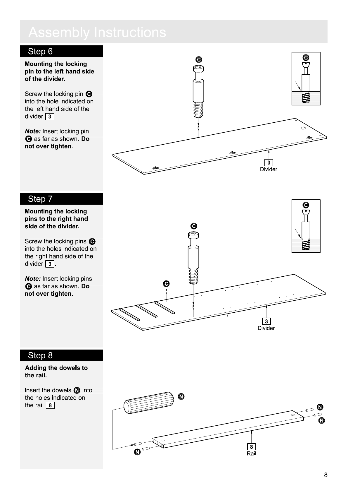
Step 6
M
ounting the locking
pin to the left hand side
of the divider
Screw the locking pin
into the hole indicated on
the left
divider
Note:
Insert locking pin
C
as far as shown
not over tighten
.
hand side of the
.
3
.
.
Do
C
Step 7
M
ounting the locking
pins to the right
side of the divider
hand
.
C
3
Divide
r
C
C
C
.
Do
C
s
Screw the locking pins
into the holes indicated on
the right
divider
Note:
C
as far as shown
not over tighten
hand side of the
.
3
Insert locking pin
.
Step 8
Adding the dowels to
the rail.
nsert the dowels
I
he holes indicated on
t
.
8
he rail
t
N
into
C
3
Divide
r
N
N
N
N
8
Rail
8

A
ss
Step 9
e
m
b
l
y
I
n
s
t
r
u
c
t
i
on
s
Adding the miniblocks
to the plinths
Inser
t the miniblocks
into the holes indicated on
the plinths
12
.
and
13
S
.
S
S
Plinth, fron
S
S
12
Plinth, ba
13
t
ck
S
S
S
Step 10
M
ounting the plinths to
the bottom
Fix the plinths
to the bottom
screws in the miniblocks
.
S
The front plinth
be placed near the
chamfered edge of the
bottom.
.
12
9
and
using
13
mus
13
t
12
13
Plinth, fron
Plinth, ba
t
ck
9
Bottom, lar
ge
9

A
ss
e
m
b
l
y
Step 11
Adding the plinths and
the rail to the left
side
.
Fit the rail
plinths
the left
See
page 4 "Function of
8
and the
12
and
hand side
13
cam and locking pin".
Place the large cams
into the holes indicated
arrows pointing towards
the side / locking pins
To tighten cams: Turn to
he right using a
t
screwdriver.
hand
onto
1
.
.
A
,
I
n
s
t
r
u
c
Chamfer = front
A
t
i
on
A
Bottom
s
9
13
Plinth, fron
t
8
Rail
1
Side, lef
t
A
Step 12
Adding the divider to
the plinths and the rail
Fit the divider
bottom
.
8
See
page 4 "Function of
9
and the rail
cam and locking pin".
Place the large cam
into the hole indicated,
arrow pointing toward the
divider / locking pin.
To tighten cams: Turn to
he right using a
t
screwdriver.
Finally fix the divider
onto the plinths
13
using the miniblo
.
S
.
3
onto the
A
3
12
and
cks
R
abbet = Back
A
8
Rail
12
Plinth, ba
ck
Bottom
3
12
9
S
13
3
Divide
12
r
10
A
ss
e
m
b
l
y
I
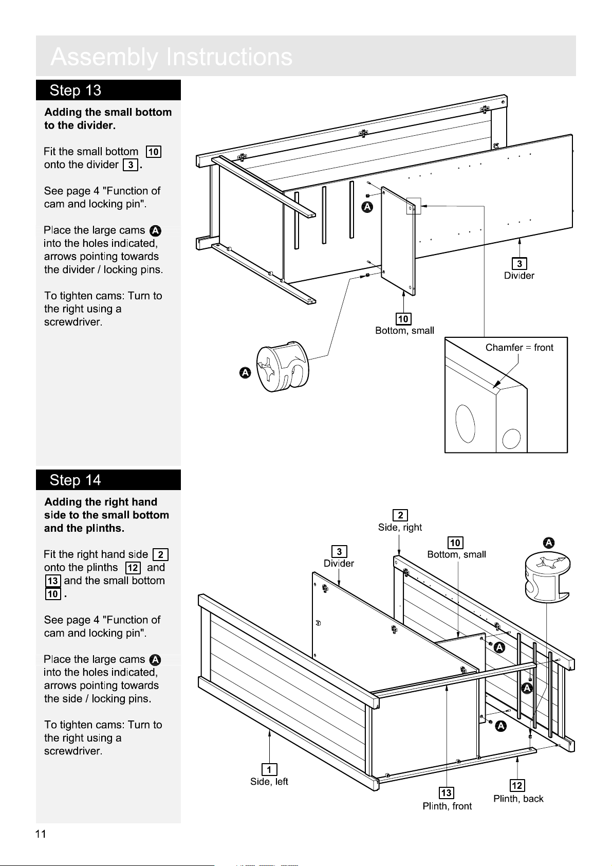
Step 13
Adding the small bottom
to the divider
Fit the small bottom
onto the divider
See
page 4 "Function of
cam and locking pin".
Place the large cams
into the holes indicated
arrows pointing towards
the divider
.
10
.
3
A
,
/ locking pins
.
n
s
t
r
u
c
t
i
on
s
A
3
Divide
r
To tighten cams: Turn to
he right using a
t
screwdriver.
Step 14
Step 14
Adding the right
side to the small bottom
hand
and the plinths.
Fit the right
onto the plinths
13
and the small bottom
.
10
hand side
12
and
10
Bottom, sma
A
2
3
Divide
r
2
Side, righ
ll
t
10
Bottom, sma
Chamfer = front
A
ll
See
page 4 "Function of
cam and locking pin".
Place the large cams
into the holes indicated
arrows pointing towards
the side / locking pins
To tighten cams: Turn to
he right using a
t
screwdriver.
11
.
A
,
1
Side, lef
t
13
Plinth, fron
t
A
A
A
12
Plinth, ba
ck

A
ss
e
m
b
l
y
I
n
s
t
r
u
c
t
i
on
s
Step 15
M
ounting the locking
pins to the top.
Screw the locking pins
C
into the holes
7
indicated on the top
Note:
Insert locking pin
C
as far as shown
not over tighten
.
.
Do
.
Step 16
s
C
C
C
C
C
7
T
C
op
C
M
ounting the magnets
to the top.
Fix the m
the top
D
into the pre-drilled
holes.
It is important that t
m
agnetic part points
towards the front edge of
the top.
agnets
7
using screws
H
to
he
T
7
op
D
D
D
H
H
D
H
H
Front edge
Front edge
12
A
ss
e
Step 17
m
b
l
y
I
n
s
t
r
u
c
t
i
on
s
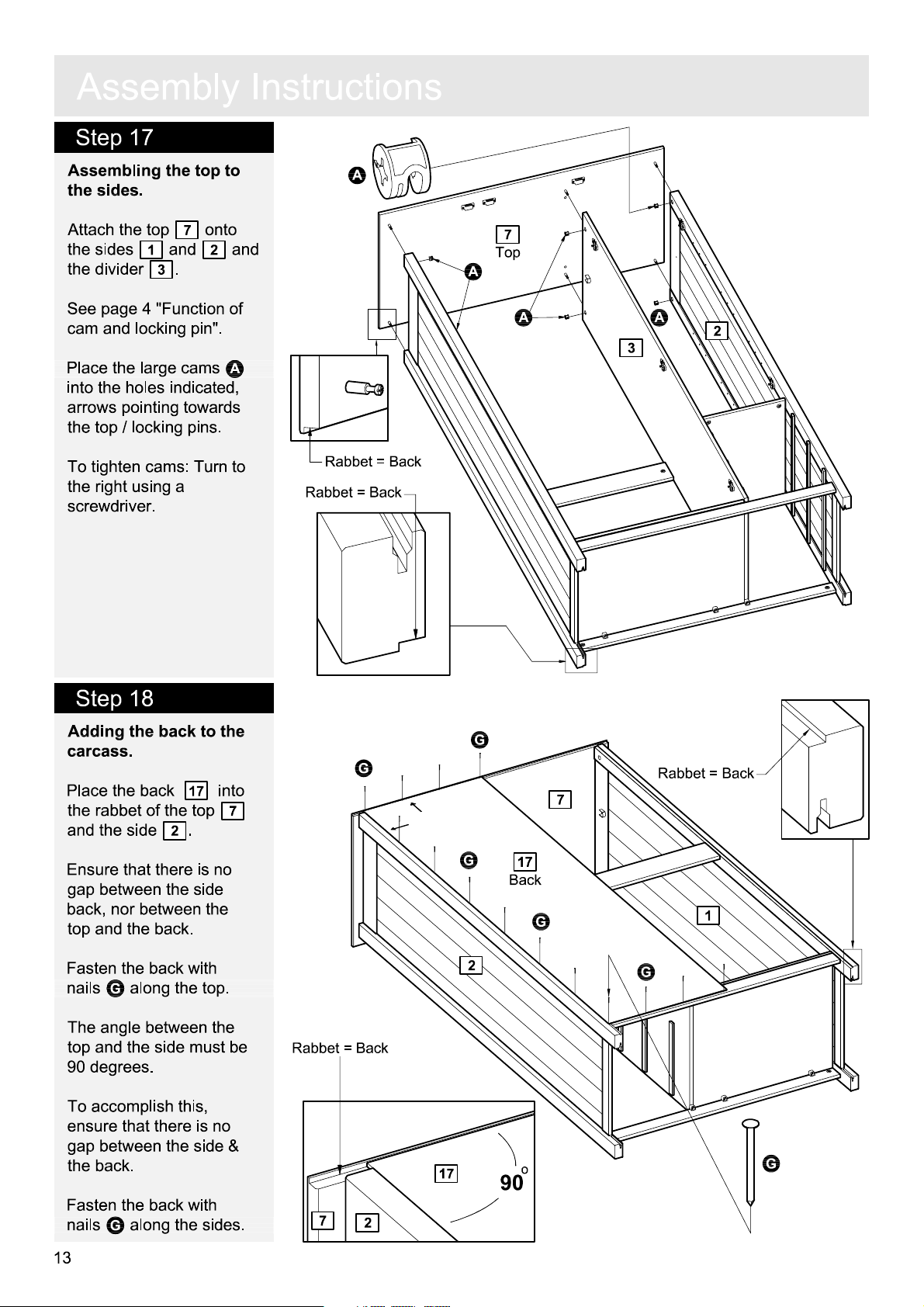
Assembling the top to
the sides
Attach the top
the sides
he divider
t
See
.
1
and
.
3
page 4 "Function of
7
onto
2
and
cam and locking pin".
A
Place the large cams
into the holes indicated
,
arrows pointing towards
the top / locking pins
.
To tighten cams: Turn to
he right using a
t
screwdriver.
A
7
R
abbet = Back
R
abbet = Back
T
op
A
A A
3
2
Step 18
Adding the back to the
carcass.
Place the back
the rabbet of the top
and the side
Ensure that there is no
gap betw
back, nor betw
top
Fasten the back with
nails
The
top
een the side
and the back.
G
al
angle betw
and the side must be
90 degrees.
To accomplish this
ensure tha
gap betw
the back
Fasten the back with
nails
een the side &
.
G
al
17
into
2
.
een the
ong the top
een the
,
t there is no
ong the sides.
.
7
G
G
G
Back
2
R
abbet = Back
7
2
17
90
7
17
G
o
R
abbet = Back
G
1
G
13
 Loading...