

Argos TX-0101 ASSEMBLY INSTRUCTIONS
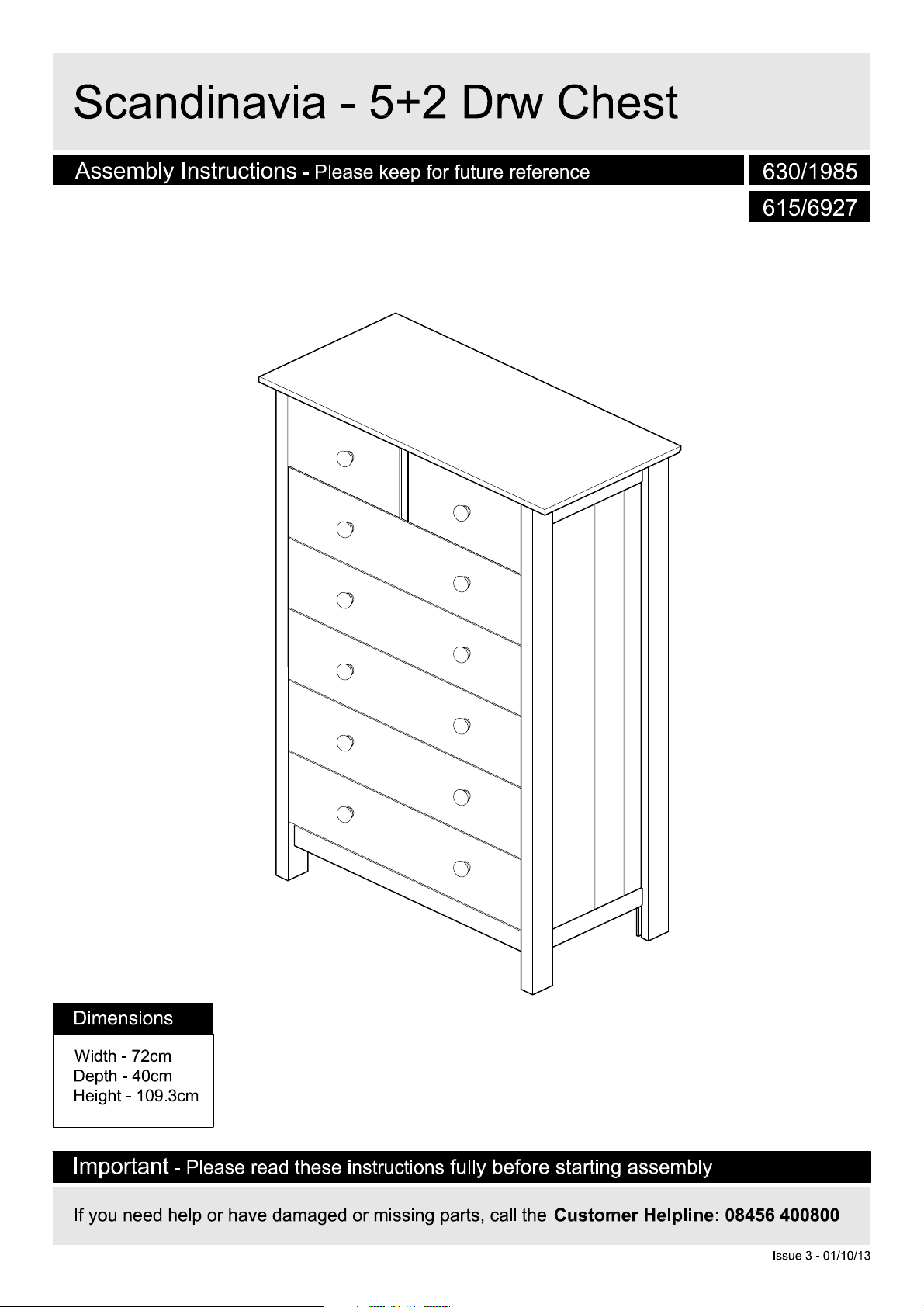
S
c
and
i
na
v
i
a
-
5
+
2
D
r
w
C
he
s
t
A
ssembly Instructi
on
s
- Please k
eep for future reference
630/1985
615/6927
Dimension
Width - 72cm
Depth - 40c
Height -
Import
If you need help or have dam
s
m
109.3cm
- Please r
an
t
ead these instructions
fully before starting assembly
aged or missing parts, call the
Customer Helpline: 08456 400800
Issue 3 - 01/10/13
!
Important
S
a
f
e
t
-
Please r
y
and
ead these instructions fully before starting assembl
C
a
r
e
A
d
v
i
c
e
y
Check you have all t
com
ponents and tools listed
pages 2
Remove all fittings from t
plastic bags
into their gr
Keep children
away from the work area, small
parts could choke if swallowed
Make sure you have enough
space to layou
starting
Only clean using a damp clot
and mild detergen
bleach or abrasive cl
.
Care
and 3
.
and s
oups.
and animal
t the parts before
and maint
he
on
he
eparate the
s
enance
t, do no us
eaners
m
.
e
.
Do not stand on
the pr
oduct, this could
cause dam
Assemble the item as clos
to its final position (in the same
room) as possible.
Assemble on a soft leve
surface to avoid damaging the
un
it or your floor
Parts of the assembly will be
easier with 2
From time to time check tha
h
here are no loose screws
t
this uni
age
t.
.
.
people
.
l
e
on
t
We do no
use of powe
dr
inserting screws
as this could damage the unit.
Only use
Dispose of all packaging
carefully
This product should not be
discar
waste. Take to your loca
authority waste disposal centre
ded with
recomm
ill/drivers
hand screwdrivers
and res
ponsibly.
household
t
end the
r
for
l
,
.
.
Note:
if r
equired the nex
page can be cut out and used
as reference throughou
assembly. K
these instructions for future
reference.
1
eep this page wit
t
t t
he
h
If you have damaged or missing components
C
o
m
ponen
t
s
-
P
ane
l
s
call the
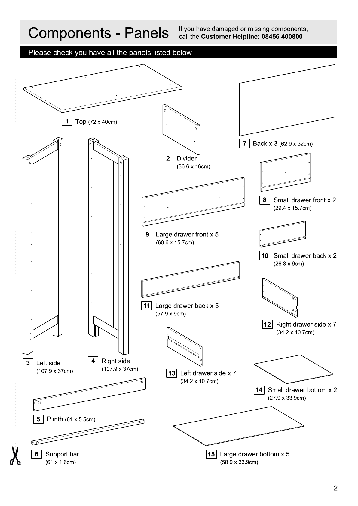
Please check you have all the panels listed below
Customer Helpline: 08456 400800
,
1
(72 x 40cm)
Top
2
Divider
(36.6 x 16cm)
9
Large drawer front x 5
(60.6 x 15.7cm)
7
Back x 3
(62.9 x 32cm)
8
Small drawer front x 2
(29.4 x 15.7cm)
Small drawer back x 2
10
(26.8 x 9cm)
3
Left side
(
107.9 x 37cm
5
6
)
Plinth
(61 x 5.5cm)
S
upport bar
(61 x 1.6cm)
4
Right side
(
107.9 x 37cm
)
11
Large drawer back x 5
(57.9 x 9cm)
Left drawer side x 7
13
(34.2 x 10.7cm)
14
15
Large drawer bottom x 5
(58.9 x 33.9cm)
12
Right drawer side x 7
(34.2 x 10.7cm)
Small drawer bottom x 2
(27.9 x 33.9cm)
2
C
o
m
ponen
t
s
-
F
i
tt
i
ng
s
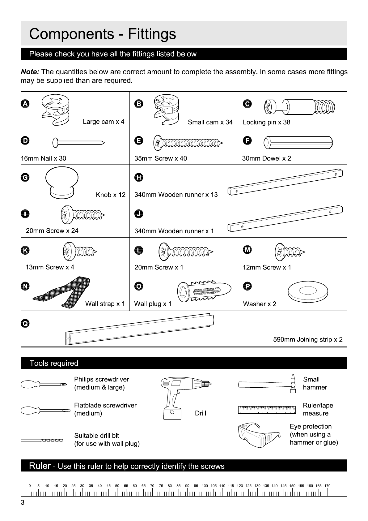
Please check you have all the fittings listed belo
Note:
may be s
16mm Nail x
The quantities below are correct am
upplied than are r
A
D
30
G
I
20mm Screw x
Large cam x 4
24
equired.
K
nob x 12
oun
t to complete the assembly
B
E
35mm Screw x
H
340mm Wooden r
J
340mm Wooden r
w
Small cam x
40
unner x
unner x
13
1
C
34
Locking pin x
F
30mm Dowel x
. In some cases more fittings
38
2
K
13mm Screw x
N
Q
Tools requir
4
Wall strap x
1
ed
Philips screwdrive
(medium & large
Flatblade screwdrive
(medium)
Suitable drill bit
(for use with wall plug
r
)
L
20mm Screw x
O
Wall plug x 1
r
)
M
1
12
mm Screw x 1
P
Washer x 2
590mm Joining strip x 2
Sma
ll
Drill
hamme
0
10
70
50
60
40
30
20
8090100 110
120
150
130
140
Ruler/tape
measur
r
e
Eye protection
(when using
ha
mmer or glue)
a
Ruler
0
3
- Use this ruler to help correctly identify the screws
55
35
30
5
10
25
15
20
50
45
40
65
60
75
70
9080
85 95
100
105
110
115 125
120
130
135
145 155 165
140
150
160
170
C
o
m
ponen
t
s
-
K
1
e
y
D
i
ag
r
a
m
7
7
3
7
2
Q
6
Q
5
4
10
14
13
11
12
8
12
x 2
F
un
c
t
i
on
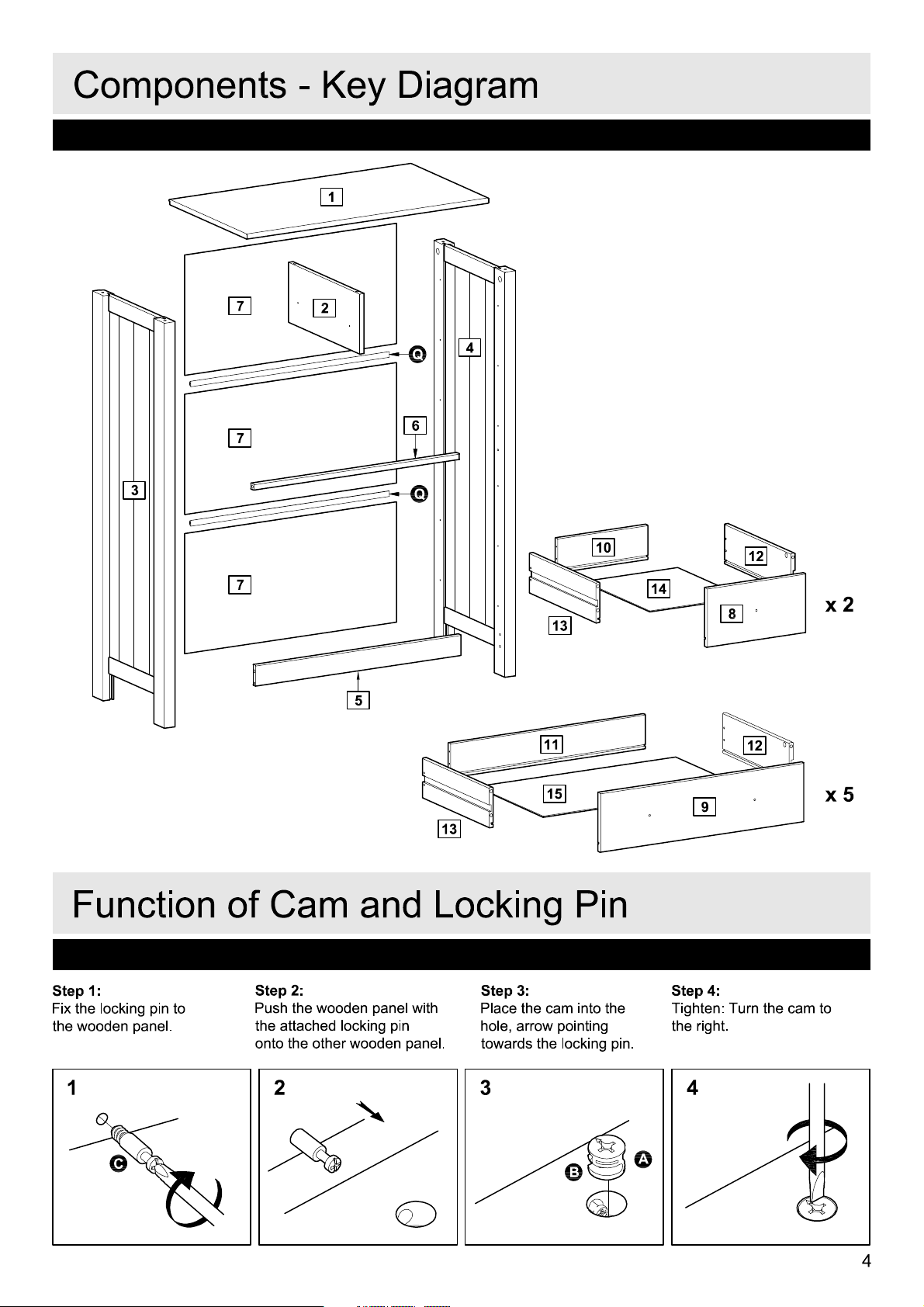
Step 1
:
Fix the locking pin to
the wooden panel.
1
C
o
f
C
a
m
and
Step 2
:
Push the wooden panel with
the attac
onto the other wooden panel.
hed locking pin
2
13
Lo
ck
i
ng
Step 3
:
Place the cam into t
hole, arrow pointing
towards the locking pin
3
15
P
B
i
n
he
9
Step 4
:
Tighten: Turn the cam to
he righ
t
.
A
t.
4
x 5
4

A
ss
e
m
b
l
y
Step 1
Inserting the dowels to
the plinth.
I
n
s
t
r
u
c
t
i
on
F
s
Inser
t the dowels
he holes indicated on
t
the plinth
5
F
into
.
Step 2
M
ounting the locking
pins to the sides
Screw the locking pins
C
into the holes
indicated on the side
3
Note:
C
as far as shown
not over tighten
4
and
Insert locking pin
.
s
.
.
Do
.
s
5
Plinth
C
3
Side, lef
t
F
C
C
C
C
4
Side, righ
t
5
 Loading...