

Argos TX-0006 ASSEMBLY INSTRUCTIONS
Scandinavia
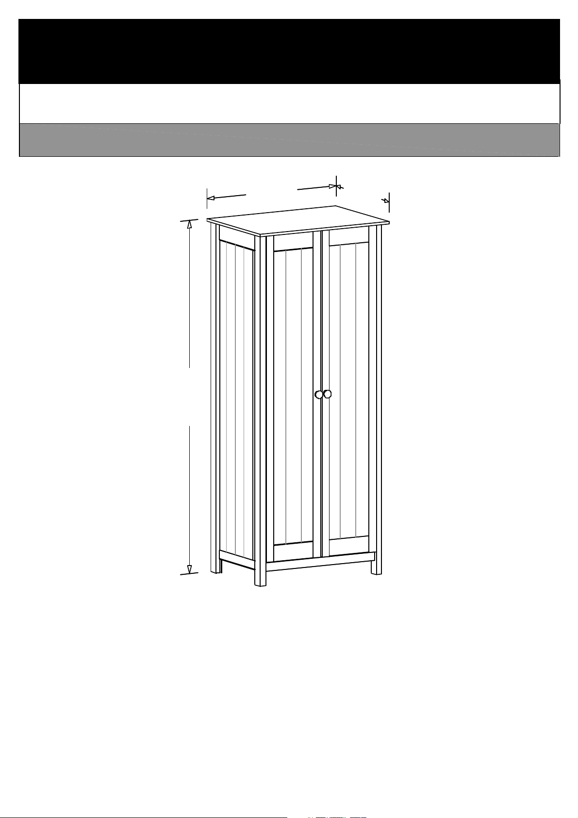
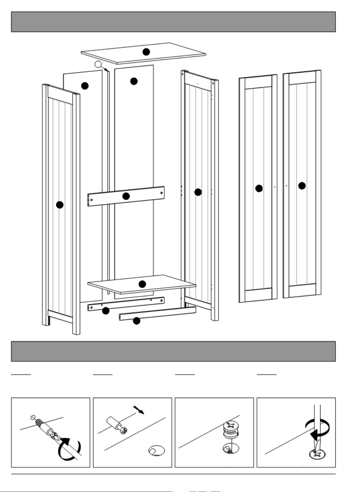
2 DOOR ROBE
750mm
530mm
1799mm
Page 1 of 18 2 door robe
Please sort out all parts before you begin to assemble the item.
This to make sure you always use the correct part.
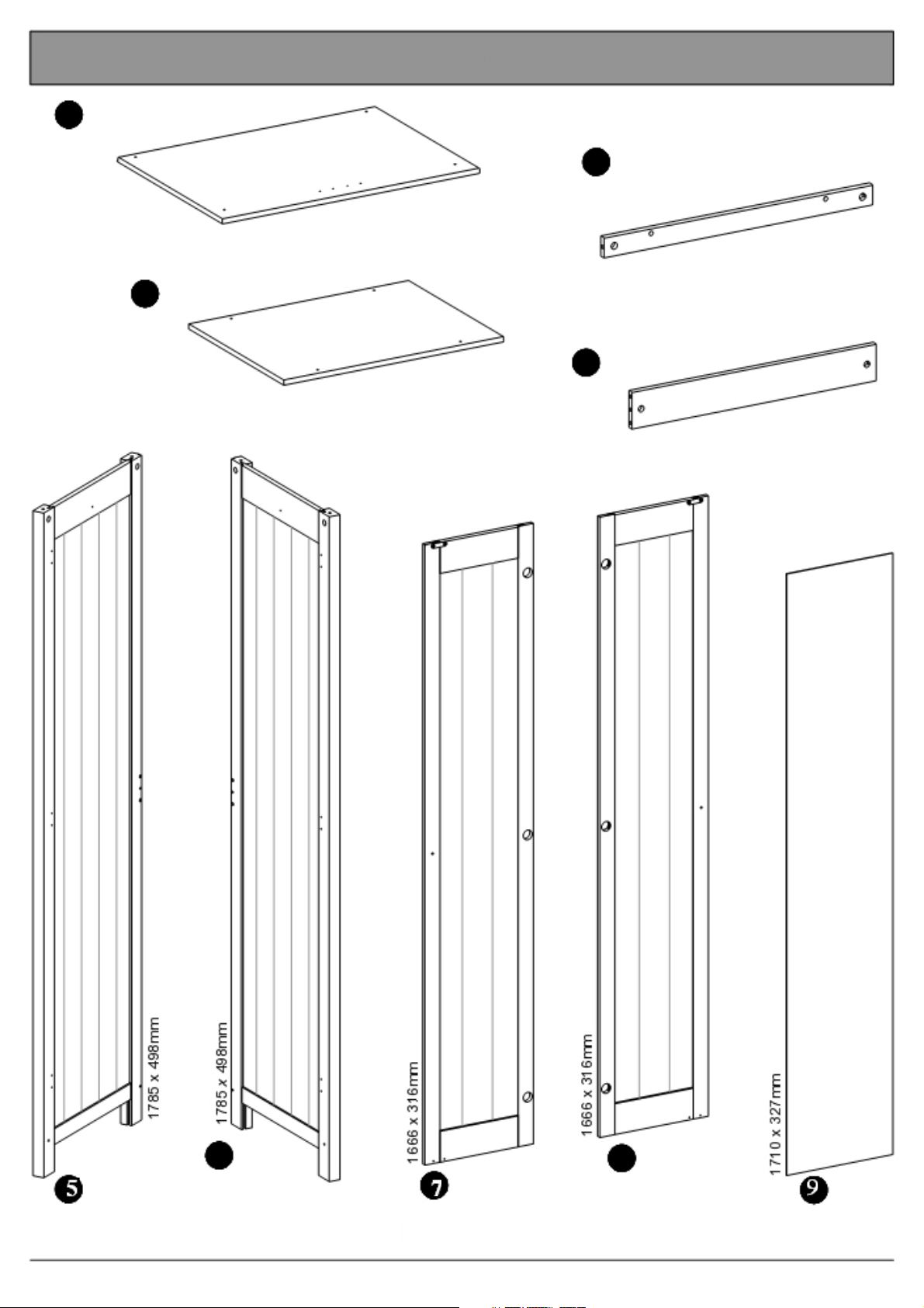
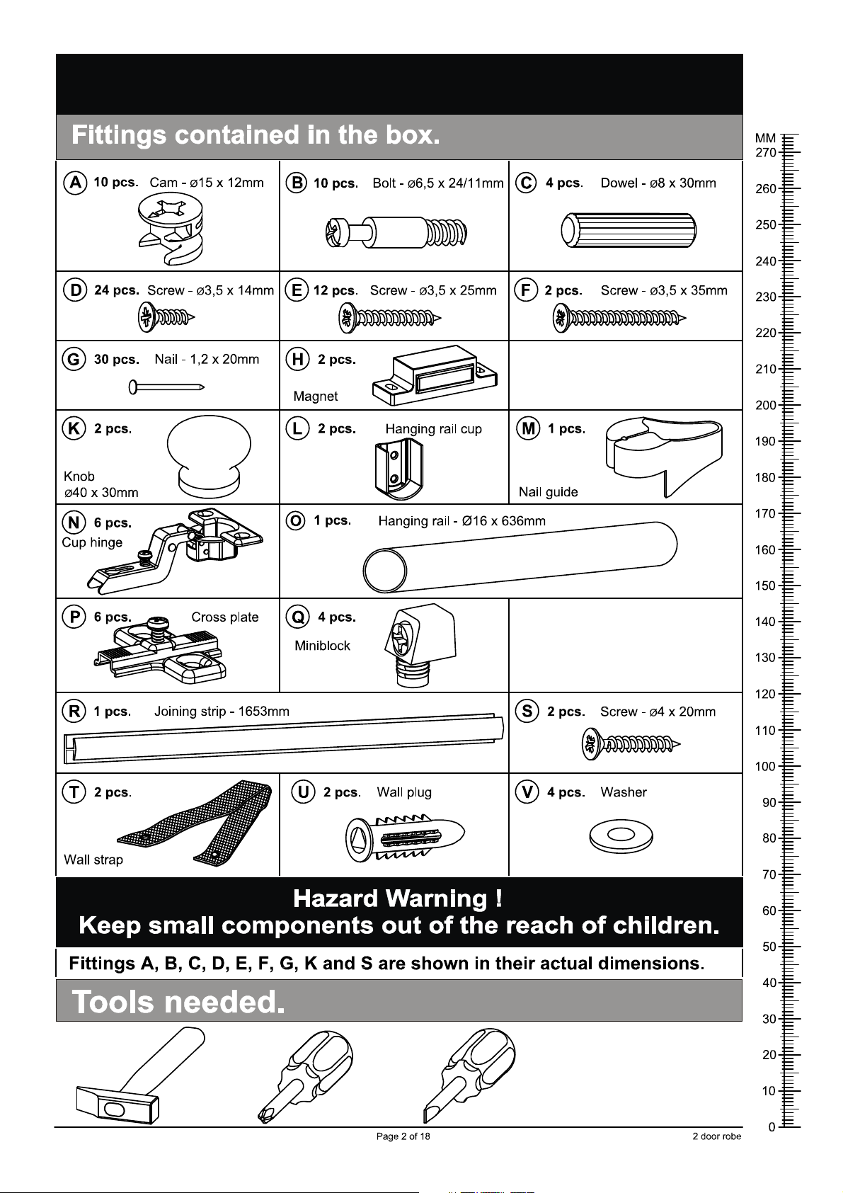
Wooden parts contained in the box.
1 Top
1 pcs.
750 x 530mm
3 Bottom
1 pcs.
640 x 480mm
2 Plinth
2 pcs.
640 x 45mm
4 Support Rail
1 pcs.
640 x 90mm
1 pcs.
Side, left
6 Side, right
1 pcs. Door, left
1 pcs.
Page 3 of 18
8 Door, right
1 pcs.
Back
2 pcs.
2 door robe
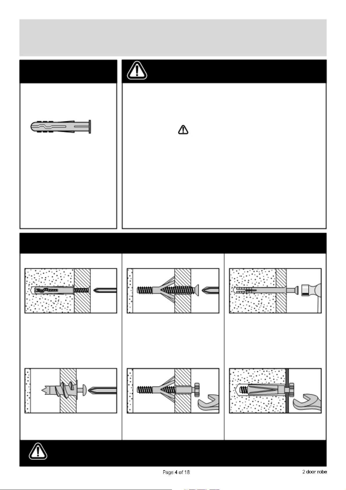
A Guide to - Wall Mounting & Fixings
Important note:
If plastic wall plugs
are supplied with your
product:
- these are only suitable for
use in masonry walls.
If you are in any doubt about
the correct wall plugs for
your wall, seek professional
advice.
Failure of the product due to
using incorrect fixings is the
responsibility of the installer.
Important:
When drilling into walls always
check that there are no hidden wires or pipes etc.
Make sure that the screws and wall plugs being used
are
suitable for supporting your unit. Consult a qualified
tradesperson if you are unsure.
Hints:
1: General rule:
if you are not sure.
2: Ensure you use the recommended drill bit to match the wall
plug and hole size.
3: Ensure you drill the hole horizontally, do not force the drill or
enlarge the hole.
4: Take extra care when drilling high walls, ceilings and ceramic
tiles. Ensure wall plugs are inserted beyond the thickness of
the ceramic tiles to avoid the tiles splitting or cracking.
5: Ensure wall plugs are well fitted and are a tight fit in the
drilled hole.
Always use a larger screw and wall plug
Types of walls
No.1 “General Purpose” wall plug No.3 “Cavity Fixing” wall plug
Generally aerated blocks should not
be used to support heavy loads, use
a specialist fitting in this case. For light
loads, general purpose wall plugs can
be used.
No.2 “Plasterboard” wall plug
You can use one of the following types of wall plug if your walls are made
of brick, breeze block, concrete, stone or wood.
For use with plasterboard partitions or
hollow wooden doors.
No.4 “Cavity Fixing-Heavy Duty”
wall plug
No.5 “Hammer Fixing”
For use with walls stuck
plasterboard. The hammer fixing allows
it to be fixed to the wall rather than the
plasterboard. Always check the fixing
is secure to the retaining wall.
No.6 “Shield Anchor” wall plug
Heavy loads
wall plug
with
For use when attaching light loads on
to plasterboard partitions.
Care &
Maintenance
For use when fitting or supporting
heavy loads such as shelving, wall
cabinets and coat racks.
Safety: Always check the fitting
and location to ensure your safety
in and around the home.
For use with heavier loads such as TV
& HiFi speakers and satelite dishes etc.
Fitting: From time to time check
the fitting to ensure the wall plugs
or screws do not become loose.
Key diagram.
1
R
9
5
9
4
6
7
8
3
2
2
Function of cam & bolt.
Step 1: Step 2: Step 3: Step 4:
Fix the Bolt to the
wooden Panel.
Push the wooden Panel
with the attached Bolt onto Hole, arrow pointing the Right.
the other wooden Panel. towards the Bolt.
Place the Cam into the
1 2 3 4
Tighten: Turn the Cam to
Page 5 of 18
2 door robe
1. Mounting the cross plates to the sides.
Fix the cross plates
"P" to the sides "5" &
"6" using the screws
"E" into the holes
indicated.
It is important that the
cross plates is placed
exactly as shown.
The short end of the
cross plates must
point towards the front
edge of the sides.
For the left hand side See fig. 1.1
For the right hand side
- see fig. 1.2
Short end
Front
Fig. 1.1 E
E
6 Pcs.
Long end
P
3 Pcs.
5
E
P
6
Side, right
P
Front
E
P
E
P
E
P
E
P
E
6 Pcs.
5
Side, left
Fig. 1.2
Front
Long end
Short end
P
3 Pcs.
6 Front
Page 6 of 18
2 door robe
2. Mounting the Hanging Rail Cups to the Sides.
Fix the hanging rail cups
"L" onto the sides "5"
and "6" using screws
"D" into the pre-drilled
holes.
See fig. 2.1
Side, right
5
Side, left
D
6
L
D
L
D
4 pcs.
Fig. 2.1
3. Mounting the bolts to the sides.
Screw the bolts "B"
into the holes
indicated on the sides
"5" and "6".
B
6 pcs.
B B
B
5
Side, left
B
L
2 pcs.
B
6
Side, right
Page 7 of 18 2 door robe
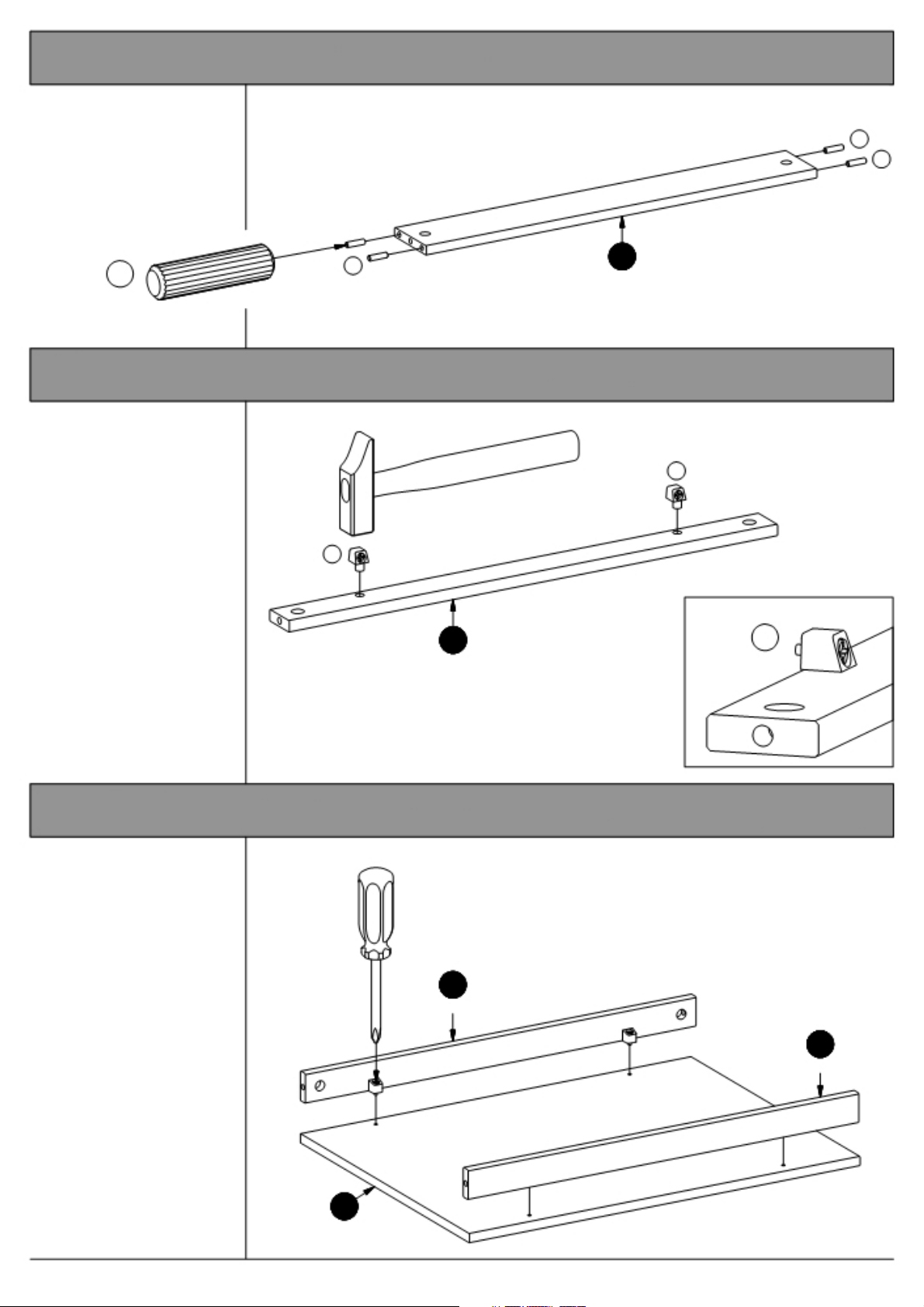
4. Adding the dowels to the support rail.
Knock the dowels "C"
into the holes indicated
on the support rail "4".
C
C
C
4 pcs.
C
Support Rail
5. Adding the miniblocks to the plinths.
Knock the miniblocks
"Q" into the holes
indicated on both the
plinths "2".
Q
2 Plinth
2 pcs.
4
Q
Q
4 pcs.
6. Mounting the plinths to the bottom.
Fix the plinths "2" to
the bottom "3" using
the screws in the
miniblocks "Q".
2
Plinth
3
Bottom
Fig. 5.1
2
Plinth
Page 8 of 18 2 door robe
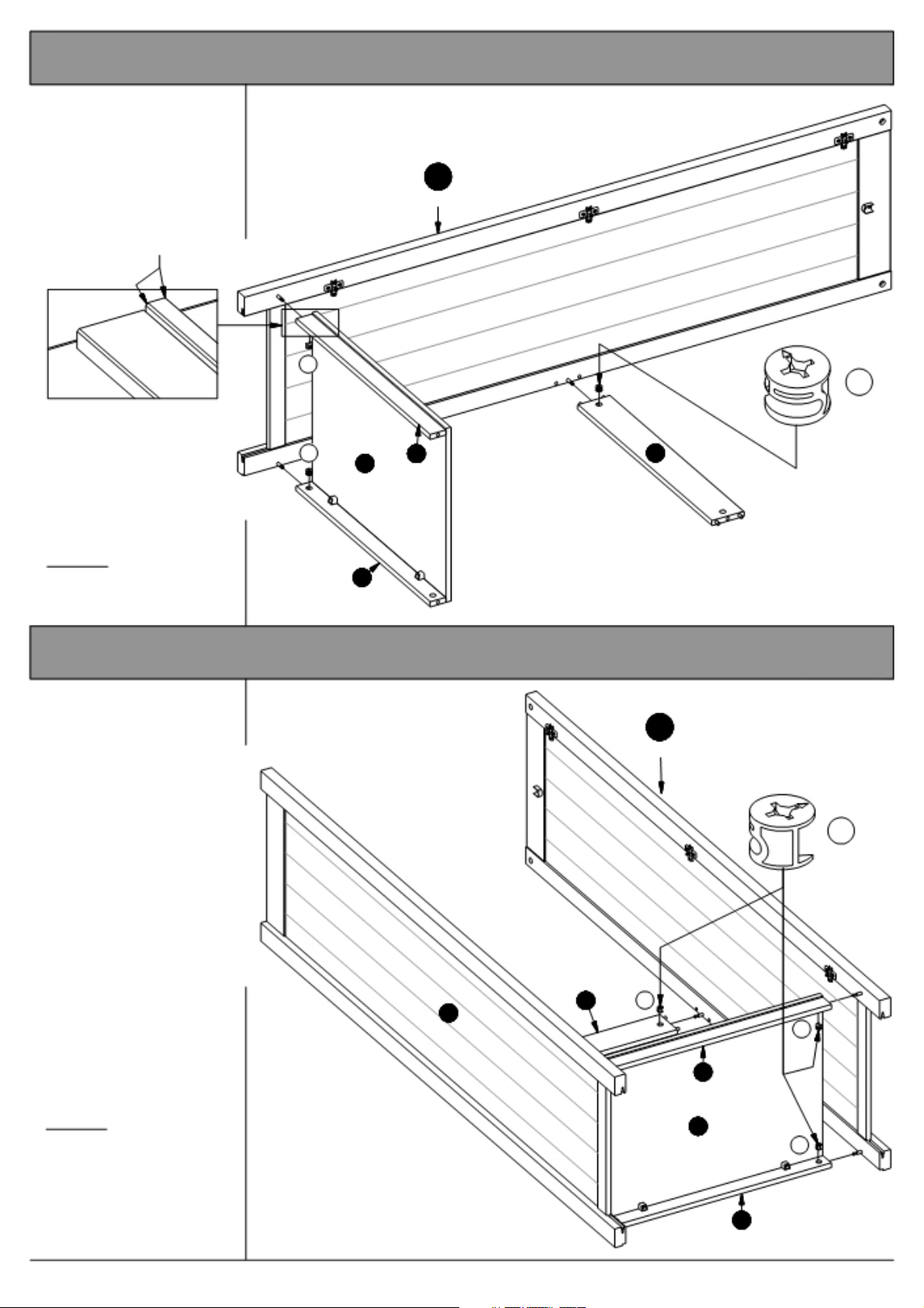
7. Adding the plinths & the support rail to the left side.
Press the side "5" onto
the plinths "2" and the
support rail "4".
See page 4 "Function of
the cam and bolt".
Note the chamfer
Fig. 7.1
Place the cams "A"
into the holes indicated,
arrows pointing towards
the side / bolt.
Tighten:
Turn the cams to the
right.
Side, left
A
A 2
3
2
5
A
3 pcs.
4
8. Adding the right side to the plinths & the support rail.
Press the side "6" onto
the plinths "2" and the
support rail "4".
See page 4 "Function of
the cam and bolt".
4 A
5
Place the cams "A" into
the holes indicated,
arrows pointing towards
the side / bolt.
6
Side, right
3 pcs.
A
2
A
Tighten:
Turn the cams to the
right.
3
A
2
Page 9 of 18
2 door robe
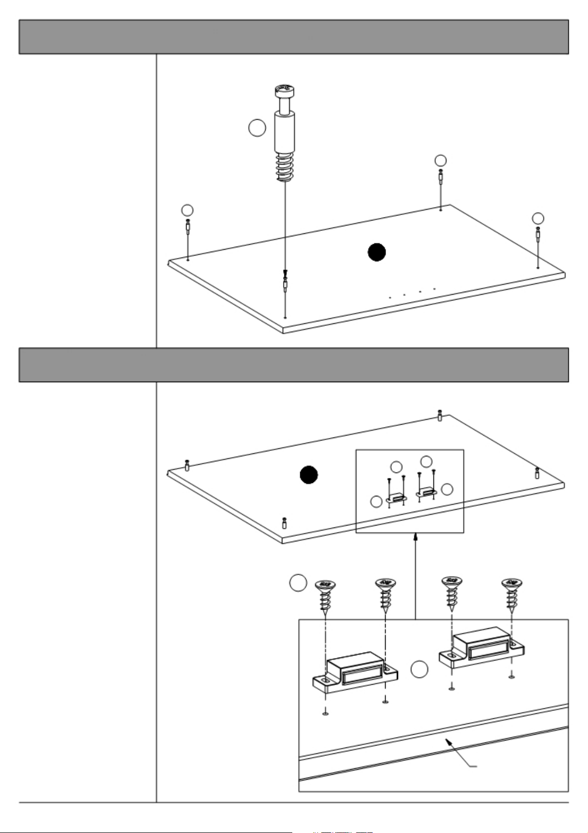
9. Mounting the bolts to the top.
Screw the bolts "B" into
the holes indicated on
the top "1".
B
4 pcs.
C
C
10. Mounting the magnets to the top.
Fix the magnets "H" to
the top "1" using
screws "D" into the
pre-drilled holes.
1
Top
C
1
Top
D D
H
H
It is important that the
magnetic part points
towards the front edge
of the top.
See fig. 10.1
4 pcs.
Fig. 10.1
Page 10 of 18
D
H
2 pcs.
Front edge
2 door robe
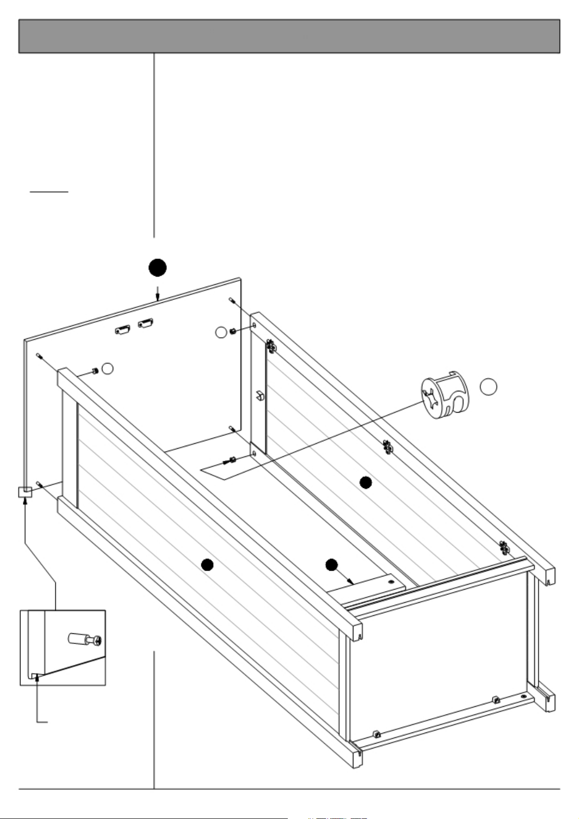
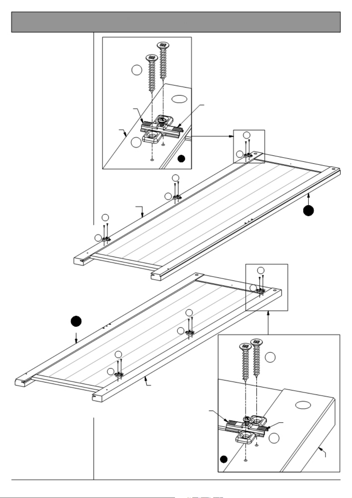
11. Assembling the top to the sides.
Lower the top "1" onto
the sides "5" and "6".
See page 4 "Function of
the cam and bolt".
Place the cams "A" into
the holes indicated,
arrows pointing towards
the top / bolt.
Tighten:
Turn the cams to the
right.
1
Top
A
A
A
4 pcs.
6
5 4
Fig. 11.1
Rabbet = Back
Page 11 of 18 2 door robe
 Loading...