

Page 1

Two Drawer TV Unit
Assembly Instructions - Please keep for future reference 237/9430
Dimensions
Width - 100cm
Depth - 40cm
Height - 45cm
Important – Please read these instructions fully before starting assembly
If you need help or have damaged or missing parts, call the Customer Helpline: 08456 400800
Issue 1 - 10/04/14
Page 2
Safety and Care Advice
Important – Please read these instructions fully before starting assembly
• Check you have all the
components and tools listed on
pages 2 and 3.
plastic bags and separate them
into their groups.
• Keep children and animals
away from the work area, small
parts could choke if swallowed.
• Make sure you have enough
space to layout the parts before
starting.
Care and maintenance
• Only clean using a damp cloth
and mild detergent, do no use
bleach or abrasive cleaners.
• Do not stand or put weight on
the product, this could cause
damage.
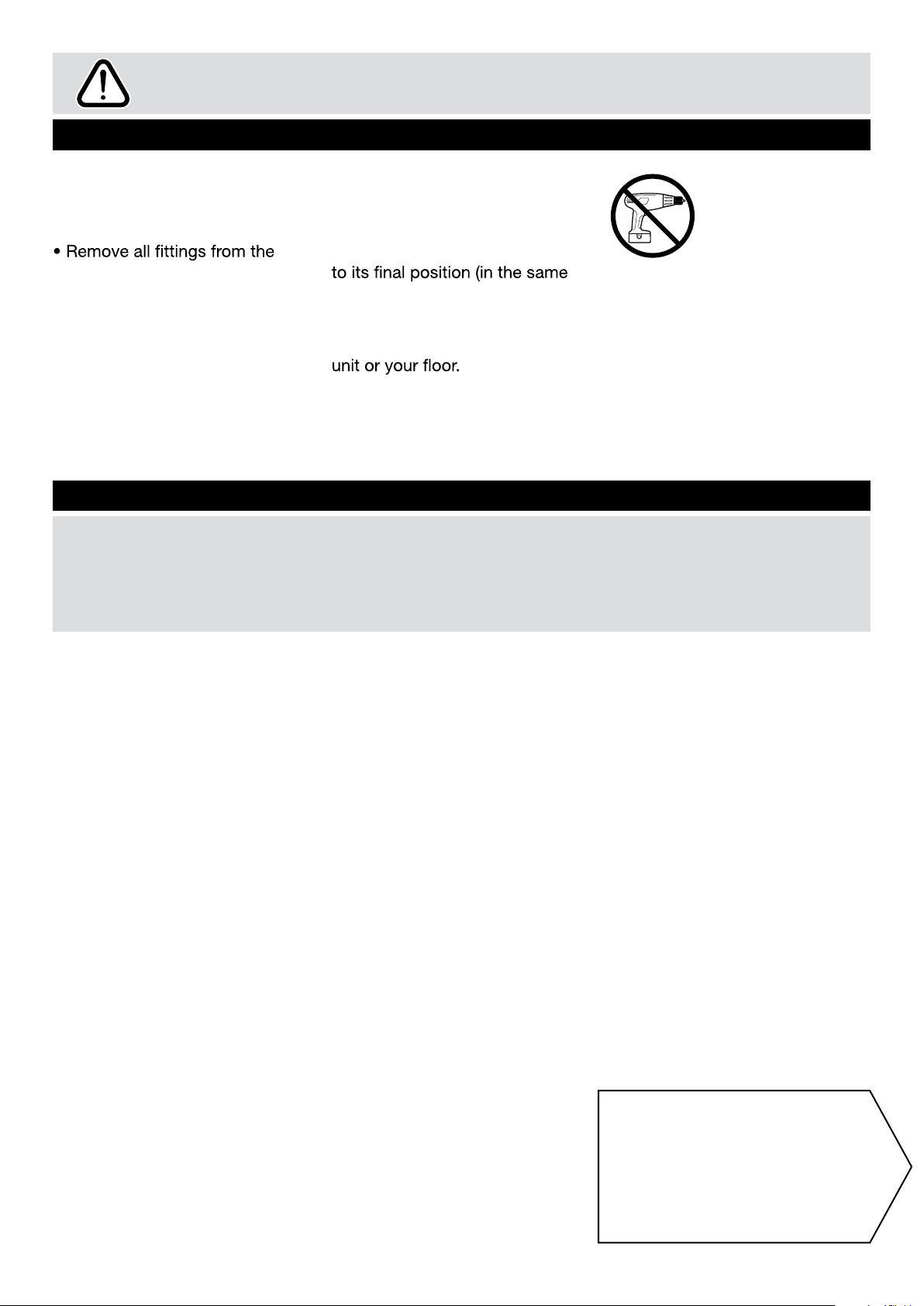
• Assemble the item as close
room) as possible.
• Assemble on a soft level
surface to avoid damaging the
• Parts of the assembly will be
easier with 2 people.
• From time to time check that
there are no loose screws on
this unit.
• We do not
recommend the
use of power
drill/drivers for
inserting screws,
as this could damage the unit.
Only use hand screwdrivers.
• Dispose of all packaging
carefully and responsibly.
• This product should not be
discarded with household
waste. Take to your local
authority waste disposal centre.
Note: if required the next
page can be cut out and used
as reference throughout the
assembly. Keep this page with
these instructions for future
reference.
1
Page 3
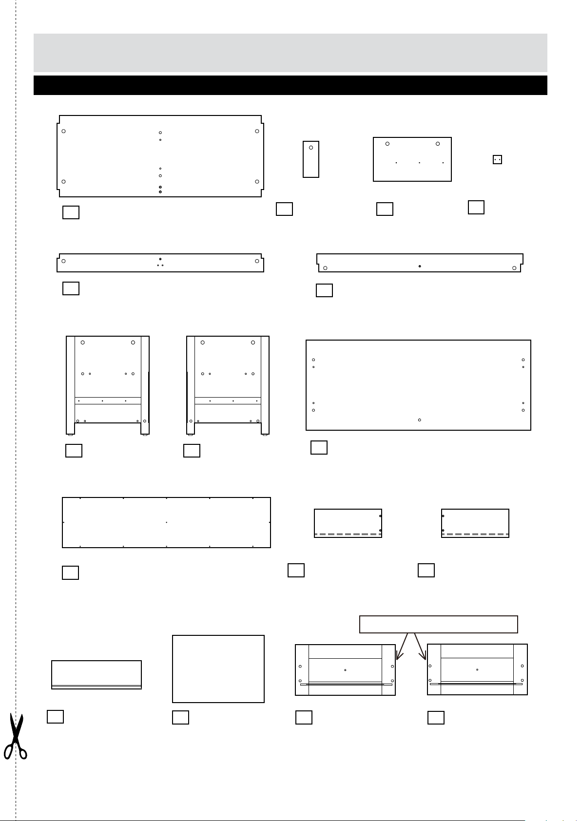
Components - Panels
Please check you have all the panels listed below
Support panel
1
5
Shelf
(918 x 362mm)
Front rail
(918 x 80mm)
2 Divider
(160 x 70mm)
6
Rear rail
3
(347 x 195mm)
(918 x 80mm)
4
Foot
(36 x 36mm)
7
10
(924 x 223mm)
13
Drawer back
panel x 2
(397 x 125mm)
Left side panel
(435 x 368mm)
Back panel
8
Right side panel
(435 x 368mm)
14
Drawer base x 2
(407 x 297mm)
9
Top panel
11
Drawer left side
panel x 2
(300 x 125mm)
15
Left drawer front
(444 x 207mm)
(1000 x 400mm)
12
Drawer right side
panel x 2
(300 x 125mm)
Note: Holes are nearer to edge.
16
Right drawer front
(444 x 207mm)
2
Page 4
110 115 120 125 130 135 140 145 150 155 160 165 170
105
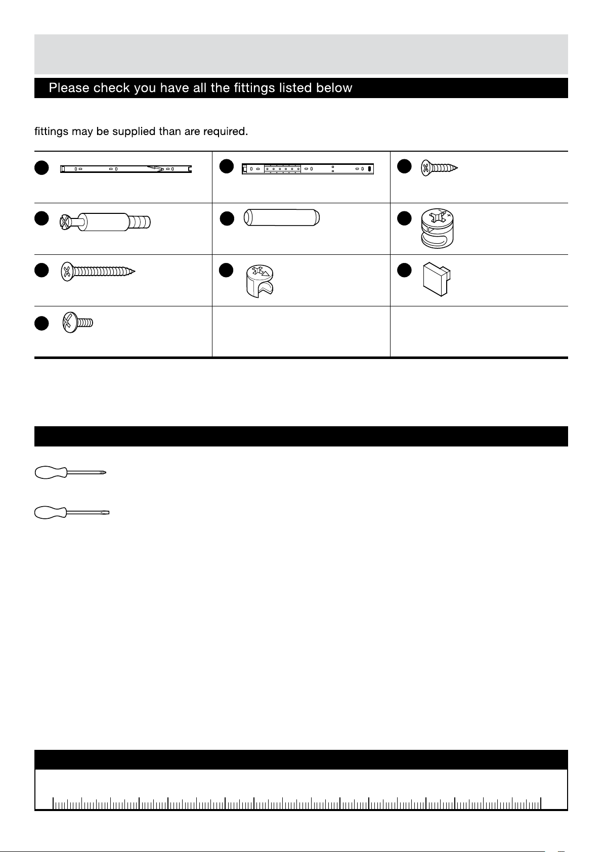
If you have damaged or missing components,
Components - Fittings
Note: The quantities below are the correct amount to complete the assembly. In some cases more
call the Customer Helpline: 08456 400800
A
D
Metal dowel x 23 Wood dowel x 20
G
35mm Screw x 14
J
Bolt x 2
B
Runner outer piece x 4Runner inner piece x 4
E
H
Small metal
cam x 8
Tools required
C
12mm Screw x 37
F
I
Large metal
cam x 15
Handle x 2
Phillips screwdriver
(medium & large)
Flatblade screwdriver
(medium)
Ruler - Use this ruler to help correctly identify the screws
0 5 10 15 20 25 30 35 40 45 50 55 60 65 70 75 80 85 90 95 100
3
Page 5

Assembly Instructions
Step 1
Dis-assemble Runners
To disassemble the
runners pull out the inner
piece of runners, to
seperate the Inner piece
A
and the Outer piece
B
, push and hold the
tab and then pull
completely out as shown.
B
A
Step 2
Screw Support panel
to Shelf using
2 Screws as shown.
1
2
G
2
1
G
4
Page 6

Assembly Instructions
Step 3
Screw metal dowels
into Shelf
1
as shown.
Note: Insert metal
dowels as far as shown.
Do not over tighten.
Firmly push wood
dowels into indicated
E
holes.
Step 4
Position Runner outer
piece onto Divider
and fix through the
indicated holes
shown using Screws .
B
C
D
D
D
E
1
C
3
B
Note: Make sure the front
end of Runner is flush
with the front edge of
Divider
.
Turn over the Divider.
Step 5
Position Runner outer
piece onto Divider
and fix through the
indicated holes
shown using Screws .
Note: Make sure the front
end of Runner is flush with
the front edge of Divider
B
3
C
.
3
Make sure the front end
of Runner is flush with
the front edge of Divider.
C
B
3
Make sure the front end
of Runner is flush with
the front edge of Divider.
5
Page 7

Assembly Instructions
Step 6
Firmly push Divider
onto Shelf , make
1
3
sure the wood and metal
dowels enter
corresponding holes.
Insert Large metal
Cams into the holes
F
on Divider so that they
are flush.
Note: Longer
leg of the cross
on the Metal
Cams must face towards
end of panel (as shown).
Then, using a Philips
Screwdriver, screw all
Metal Cams clockwise
F
until they are ‘hand tight’.
Taped edge
face upwards.
F
Long leg.
1
3
Note: Tighten all cams
in this way.
Step 7
Screw Foot to Front
5
rail using 2 Screws
G
as shown.
4
5
4
G
6
Page 8

Assembly Instructions
Step 8
Firmly push wood
dowels into the
indicated holes in
Divider .
E
3
1
Firmly push Front and
Rear rails onto
6
5
the dowels on Divider,
make sure the dowels
enter corresponding
holes.
Secure with Screws .
G
Note: Cut out on the
corner of rails should
face outwards as
shown.
Step 9
Position Runner outer
piece B onto Left side
panel and fix
through the indicated
holes shown using
Screws .
A
7
C
5
E
3
G
6
E
G
Cut out on the corner
of rails should face
outwards as shown.
C
B
Note: Rubber tube on
the runner should face
to the back panel groove
as shown.
7
7
Rubber tube on the runner
should face to the back
panel groove as shown.
Page 9

Assembly Instructions
Step 10
Screw metal dowels
into Left side panel
D
7
as shown.
Firmly push wood
dowels into indicated
E
holes.
Step 11
Two people may be
needed here.
Firmly push Left side
panel onto the end
of Shelf , Front
and Rear rails ,
make sure the wood and
metal dowels enter
corresponding holes.
Secure with Cams .
7
1
6
5
F
E
D
7
7
Lift the end of panels a
little to easily fitting dowels
into corresponding holes.
1
F
5
Step 12
Repeat Steps 9 to 11 to
assemble Right side
panel as shown.
Stand unit upright.
8
6
1
5
8
6
F
8
Page 10

Assembly Instructions
Step 13
Screw metal dowels
D
into Top panel
as shown.
Firmly push wood
dowels into indicated
E
holes.
9
9
D
E
Step 14
Two people may be
needed here.
Turn over the Top panel.
Firmly push Top panel
onto Side panels
and support panel ,
make sure the wood and
metal dowels enter
corresponding holes.
Secure with Metal
cams .
F
7 8
2
9
9
F
7
2
8
9
Page 11

Assembly Instructions
Step 15
Attach back panel
to back of the unit
using Screws .
C
10
9
C
10
7
Step
16
Position Runner inner
piece onto Drawer
side panels and
A
12
11
fix through the indicated
holes shown using
Screws .
C
Note: Make sure the
front end of Runner is
flush with the front edge
of drawer side as shown.
11
C
A
12
Make sure the front end
of Runner is flush with
the front edge of drawer
side.
10
Page 12

Assembly Instructions
Step 17
Drawer assembly
11
a: Firmly push wood
dowels into the
indicated holes in Drawer
back panel .
Fix drawer sides
to Drawer back panel
using screws .
b: Slide Drawer base
into the grooves as
shown.
E
13
11 12
13
G
14
Foiled side
face upwards.
11
13
E
G
12
13
c: Screw Metal
dowels into holes
on back of Drawer front
15
.
d:
against end of drawer
sides and firmly push to
make sure the Drawer
base enters the groove in
Drawer front.
Secure with Small metal
cams .
e:
the Drawer front using
Bolt .
D
Position drawer front
H
Attach Handle to
J
I
12
14
D
15
15
I
J
Repeat Step 17 to
assemble the other
drawer with Drawer
front .
16
11
H
Page 13

Assembly Instructions
Step 18
Slide Drawer into the
space as shown, make
sure the Runner inner
piece enters the Runner
outer piece on both
side.
Note:
notice the left
and right
drawer position, do not
reverse.
Two people may be
needed here.
In case of reversed
drawers
Please
15
Please notice the left
and right drawer position,
do not reverse.
16
If you reversed the
drawers, please take
Step 1 as a reference,
using the screwdriver to
push the tab on drawer
left side upwards and
keep pulling out
status, the other person
push the tab on right side
panel downwards and pull
out so that the whole
drawer can pull out from
the space.
Assembly is complete.
If you need help or have damaged or missing parts, call the Customer Helpline: 08456 400800
Shaw Spencer Hometrading Ltd. 34-38 Vale Road, Bushey. WD23 2HE.
 Loading...