

Page 1
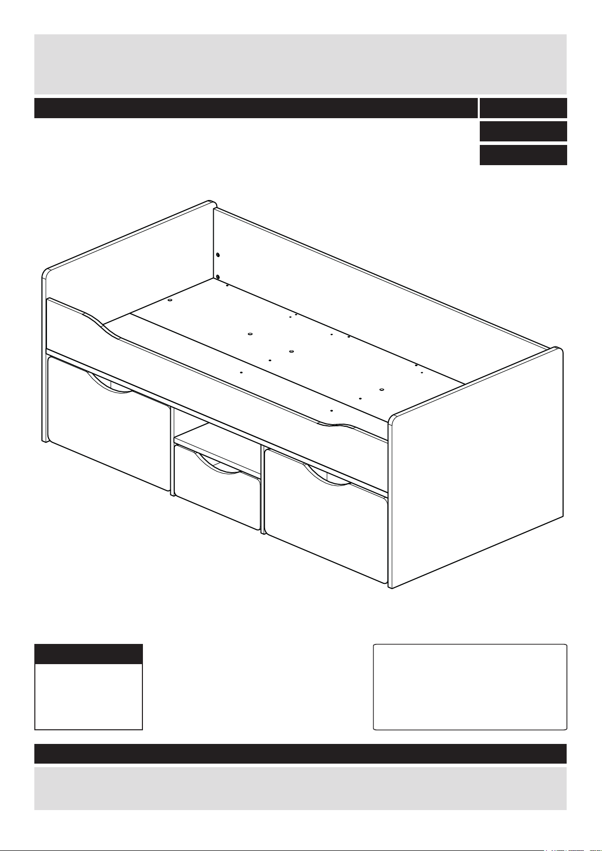
Tolgabed 90x190
DR825206
Assembly Instructions - Please keep for future reference
499/4631
487/7954
487/5877
Dimensions
Width - 195,4cm
Depth - 95,5cm
Height - 74cm
499/4631 OAK
487/7954 PINK
487/5877 BLUE
Important – Please read these instructions fully before starting assembly
If you need help or have damaged or missing parts, call the
Argos = 03456 400 800
Tip : To prevent damage,
we recommend that you
build your unit on the
carton(s) it was packed in.
Customer Helpline:
Issue: 2 - 23/12/15
Page 2

Safety and Care Advice
Important – Please read these instructions fully before starting assembly
• Check you have all the
components and tools listed
on the following pages.
• Remove all fittings from the
plastic bags and separate them
into their groups.
• Keep children and animals
away from the work area, small
parts could choke if swallowed.
• Make sure you have enough
space to layout the parts before
starting.
• During assembly do not stand
or put weight on the product,
this could cause damage.
• Assemble the item as close
to its final position (in the same
room) as possible.
• Assemble on a soft level
surface to avoid damaging the
unit or your floor.
• Parts of the assembly will be
easier with 2 people.
• To reduce
the likelihood of
damaging your
product please
ensure that your
power drill is set on a low torque
setting.
• Assembly should be carried out
by a competent adult only.
• do not use this item if any
components are missing
or damaged.
• this item is suitable for childeren
from the age of 6.
Glue safety - Take care when using glue, please follow the advice below•
Skin contact: Remove
contamination by washing with
soap and water. This procedure
should also be followed prior to
eating and drinking.
Eye contact: Rinse immediately
with clean water for 15 minutes
and seek medical advice.
If swallowed: Seek medical
advice immediately.
Care and maintenance
• Only clean using a damp cloth
and mild detergent, do no use
bleach or abrasive cleaners.
Handy Hints
• Assemble all parts and bolts
loosely during assembly, only
once the product is complete
should you fully tighten the bolts
• From time to time check that
there are no loose screws on
this unit.
• Regularly check and ensure
that all bolts and fi ttings are
tightend properly.
• This product should not be
discarded with household waste.
Take to your local authority
waste disposal centre.
•
Note: if required the next
page can be cut out and used
as reference throughout the
assembly. Keep this page with
these instructions for future
reference.
1
Page 3
If you have damaged or missing components,
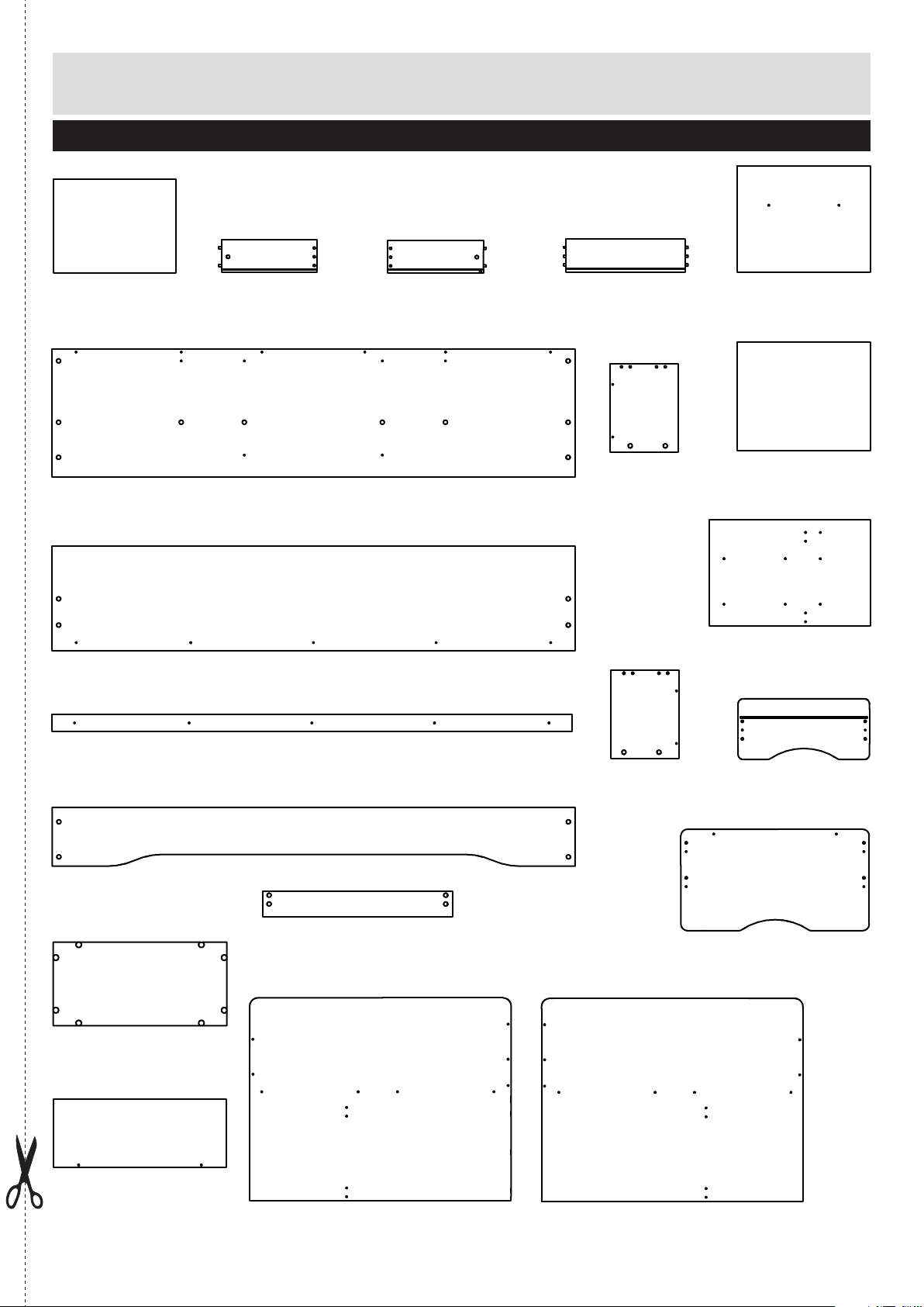
Components - Panels
call the Customer Helpline:
Please check you have all the panels listed below
03456 400 800
Drawer Base
1
(448x344x3)
BO2643
Bed bottom x 2
5
(1910x467x22)
P1874
Side back
6
(1910x383x18)
P1875
Drawer left side
2
(350x120x12,50)
LA1624
Drawer right side
3
(350x120x12,50)
LA1625
Drawer back
4
(437x120x12,50)
LA1653
^
Storagebox
Right side
(323x250x15)
P6102
Backpanel
8
(486x386x18)
P1877
Shelf
9
(486x396x22)
P1878
Mid Panel x 2
0
(386x589x18)
P2954
Bed bottom support
7
(1900x60x28)
P1876
Side Front
#
(1910x215x18)
P4747
Storagebox base x 2
$
(634x305x15)
P6100
Storagebox back x 2
%
(634x250x15)
P6101
Plinth x 4
)
(694x92x15)
P7060
Headboard
*
(955x740x22)
P6506
Footboard
(
(955x740x22)
P6507
Storagebox
&
left side x 2
(323x250x15)
P6103
Drawer front
!
(480x221x18)
P4131
Storagebox front x 2
@
(688x370x18)
P4132
2
Page 4
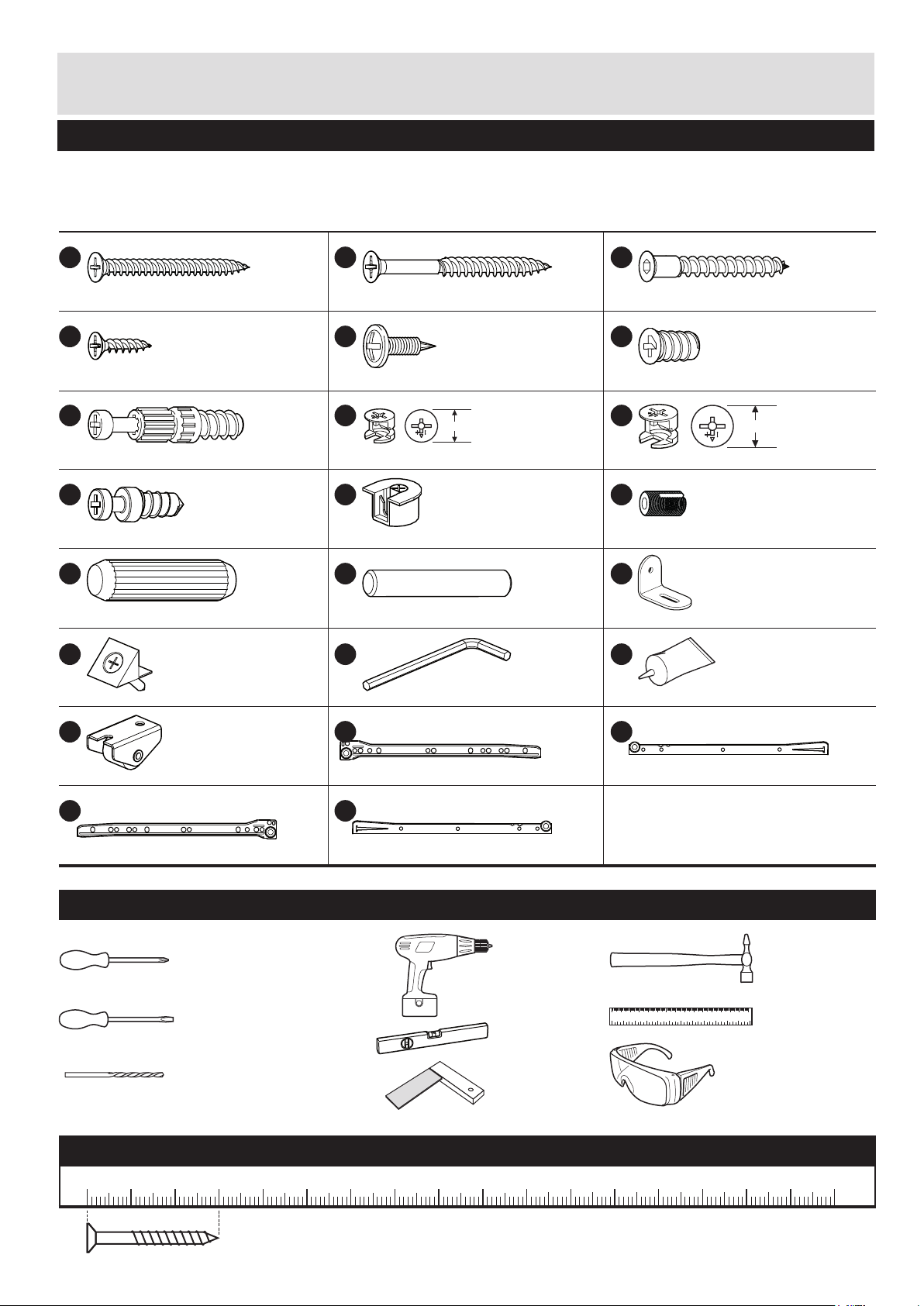
Components - Fittings
Please check you have all the fittings listed below
Note: The quantities below are the correct amount to complete the assembly. In some cases more fittings
may be supplied than are required.
A
D
Screw x 34
G
Locking screw x 42
J
Expando Screw x 16
M
Wood dowel x 24
P
FK1329
(4,5x45mm)
FK1311
(3x15mm)
FK1011
(5x24mm)
FK10561
(5x19,5mm)
FK1411
(8x30mm)
FK1250
B
E
Screw x 4
H
12mm
Small locking nut x 2
K
Expando housing x 16
N
Wood dowel x 2
Q
FK1006
(3x45mm)Screw x 5
FK1400
(4x15mm)
FK1010
(12x10mm)
FK1051
FK1410
(5x30mm)
FK1013
C
Confirmat screw x 16
F
Euro Screw x 4
I
15mm
Large locking nut x 40
L
Plug x 2
O
L-Bracket x 2
R
FK1005
(5x40mm) Screw x 14
FK1301
(6.3x10mm)
FK1012
(15x12mm)
FK1082
(5x9mm)
FK1235
FA1510
Drawerbase support x 4
S
Wheel x 10
V
Runner right part A x 1
Tools required
Phillips screwdriver
(medium & large)
Flatblade screwdriver
(medium)
6mm Suitable drill bit
(for use with wall plug)
FK1244
PM1517 RA
Allen Key x 1
T
Runner left part A x 1
W
Runner right part B x 1
(3mm)
PM1517 LA
PM1517 RB
Drill
Spirit level
Setsquare
Glue x 2
U
Runner left part B x 1
0102030405060708090 100 110 120 130 140 150
0123456
Eye protection
(when using a
hammer or glue)
PM1517 LB
Small
hammer
Ruler/tape
measure
Ruler - Use this ruler to help correctly identify the screws
0 5 10 15 20 25 30 35 40 45 50 55 60 65 70 75 80 85 90 95 100
The screws length is measured from the head to the point (30mm screw shown).
3
105
110 115 120 125 130 135 140 145 150 155 160 165 170
Page 5
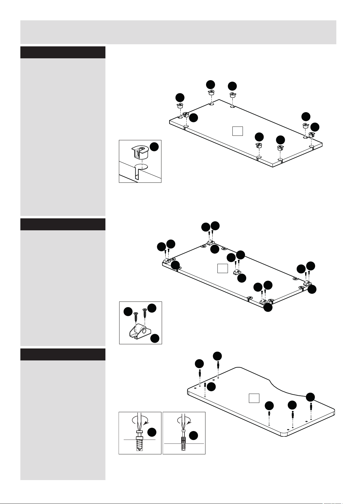
Assembly Instructions
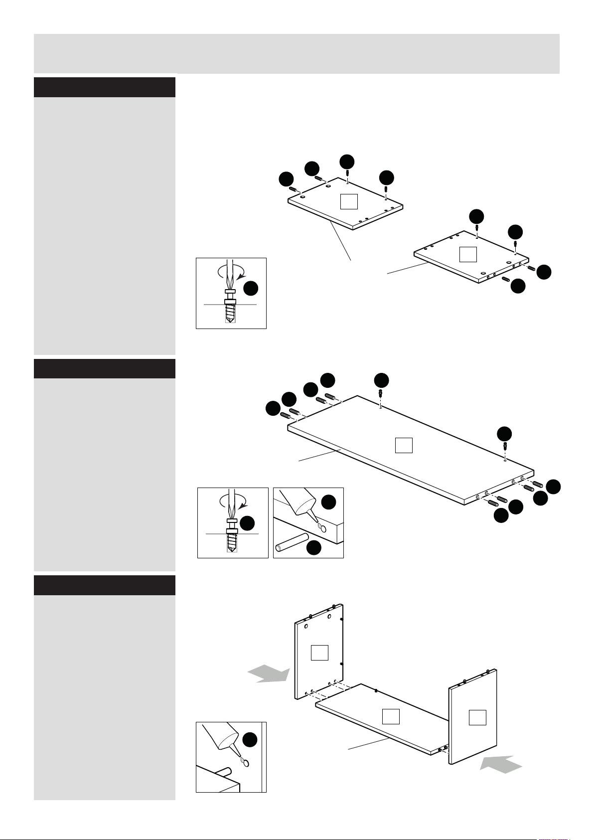
Step - 1
Insert expando housing K
into Storagebox base $.
Make sure that the expando housing K is open.
Step - 2
Position the wheel S on
the storagebox base $.
Make sure that there is
enough free space to the
edges of storagebox base
$.
Use 2 screws 15mm D to
mount each wheel S on
storagebox base $.
2x
2x
D
K
K
K
K
D
D
D
S
D
K
K
14
D
S
14
D
D
K
S
D
K
D
S
K
D
D
S
Step - 3
Screw locking screw G
into storagebox front @.
Note: Insert locking
screw G as far as shown.
Do not over tighten.
Screw expando screw J
into storagebox front @.
Note: Insert expando
screw J as far as shown.
Do not over tighten.
2x
S
G
G
J
12
J
J
G
G
G
4
Page 6
Assembly Instructions
Step - 4
Screw expando screw J
into storagebox sides
^/&.
Note: Insert expando
screw J as far as shown.
Do not over tighten.
Put dowels M into the
holes of Storagebox sides
^/&.
Step - 5
Screw expando screw J
into storagebox back %.
2x
2x
M
M
J
M
M
M
J
16
Finished
front edge
M
J
J
J
17
M
M
J
Note: Insert expando
screw J as far as shown.
Do not over tighten.
Put drop of glue R into the
8 holes of storagebox back
%.
Put dowels M into the
holes of Storagebox back
%.
Step - 6
Attaching panels
Put drop of glue R into the
8 holes of storagebox sides
^/&.
Position the 8 dowels M
of storagebox back %onto
the holes of Storagebox
sides ^/&.
2x
Finished
front edge
J
M
16
J
15
M
R
M
15
17
M
M
R
5
Finished
front edge
Page 7

Assembly Instructions
Step - 7
Insert large locking nuts I
into storagebox sides
^/&.
Make sure the ‘arrow’ on
locking nuts I points
towards the hole in the
edge of ^/&.
Position storagebox front
@ onto the unit.
Use a screwdriver to turn
locking nuts I clockwise
to lock.
2x
12
I
I
16
I
15
I
I
17
Step - 8
Attaching base
Slide storagebox base $
into the drawer from the
top until the 8 expando
screws J are totally in
the expando housing K of
storagebox base $.
Use a screwdriver to turn
expando housig clockwise
to lock.
2x
12
14
15
16
15
14
17
16
12
6
Page 8

Assembly Instructions
Step - 9
Screw locking screw G
into drawer front !.
Note: Insert locking
screw G as far as shown.
Do not over tighten.
Step - 10
Attaching panels
Put drop of glue R into the
6 holes of storagebox sides
2/3.
G
G
11
G
3
Position the 6 dowels of
drawer back 4 onto the
holes of Storagebox sides
2/3.
Step - 11
Attaching panels
Insert drawer base 1 into
the grooves of drawer
sides 2/3 and drawer
back 4.
2
R
3
4
1
2
4
7
Page 9

Assembly Instructions
Step - 12
Insert small locking nuts I
into Drawer sides 2/3.
Make sure the ‘arrow’ on
locking nuts I points
towards the hole in the
edge of 2/3.
Position drawer onto
drawer front !.
Use a screwdriver to turn
locking nuts clockwise to
lock.
I
4
2
I
1
3
I
11
Step - 13
Slide drawerbase support
P in the grooves as shown
and fix them, using the
attached screw.
Step - 14
Fix runner left part B U on
left drawer side 2 as
shown using 15mm screw
D.
Fix runner right part B W on
right drawer side 3 as
shown using 15mm screw
D.
4
P
3
P
D
D
D
W
4
D
3
1
D
1
P
D
U
11
P
D
D
2
2
P
11
8
Page 10

Assembly Instructions
Step - 15
Screw locking screw G
into headbord *.
Note: Insert locking
screw G as far as shown.
Do not over tighten.
G
G
G
G
G
18
G
G
G
G
G
G
G
Step - 16
Screw locking screw G
into footboard (.
Note: Insert locking
screw G as far as shown.
Do not over tighten.
G
G
G
G
G
G
19
G
G
G
G
G
G
G
G
9
Page 11

Assembly Instructions
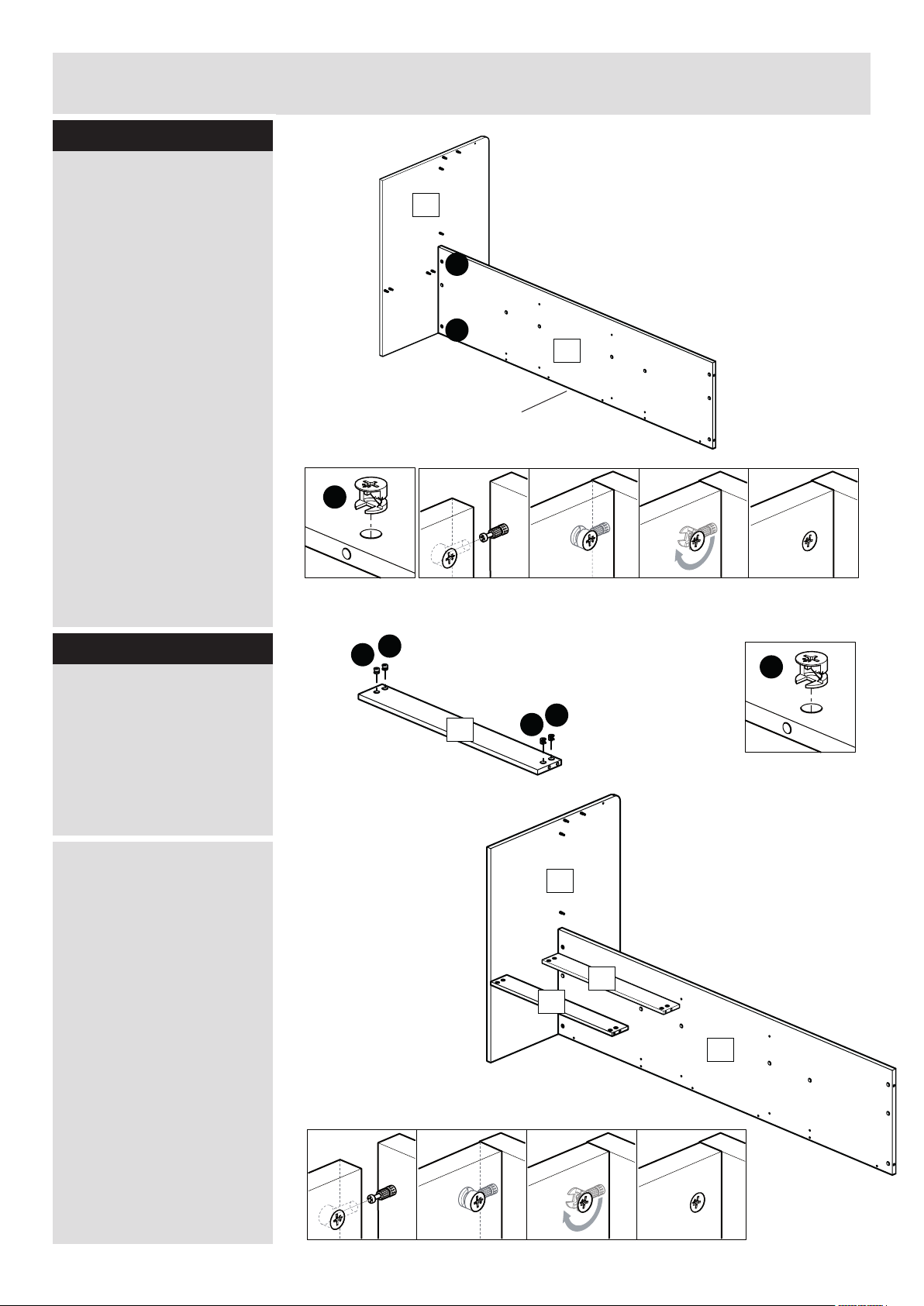
Step - 17
Put dowels N into the
holes of side back 6 .
Insert large locking nuts I
into side back 6.
Make sure the ‘arrow’ on
locking nuts I points
towards the hole in the
edge of 6.
Align holes of bed bottom
support 7 with holes side
back 6 as shown and
attach using 45mm screw
A.
Step - 18
I
A
I
Finished
front edge
A
A
A
I
I
N
Finished
front edge
6
7
A
N
I
Attaching runners
Fix runner left part A T
on mid panel 0 as shown
usesing 10mm euro screw
F into mid panel 0.
Insert 15mm screw D as
shown into mid panel 0
to fix runner left part A T.
Note: look carreful for the
right postion.
Repeat steps with mid
panel 0 and runner left
part A V.
D
D
F
D
F
T
F
T
10
D
10
DD
D D D
F
F
D
D
F
V
D
F
Finished
front edge
F
V
10
Page 12

Assembly Instructions
Step - 19
Position mid panel 0
(with left runner part A T)
onto backpanel 8. Insert
three confirmat screws C
through mid panel 0 into
backpanel 8 as shown.
Use allen key Q to turn
confirmat screw C into
panel.
C
8
9
Position shelf 9 onto mid
panel 0. Insert two
confirmat screws C
through mid panel 0 into
shelf 9 as shown.
Step - 20
Position mid panel 0
(with right runner part A
V) onto backpanel 8 and
shelf 9. Insert five confir-
mat screws C through
mid panel 0 into backpanel 8 and shelf 9 as
shown.
Use allen key Q to turn
confirmat screw C into
panel.
C
C
C
10
10
9
C
Finished
front edge
8
C
C
10
C
11
C
C
Finished
front edge
Page 13

Assembly Instructions
Step - 21
Fix shelf 9 onto backpanel 8 as shown using
45mm screw B.
Finished
front edge
10
9
8
B
B
10
Step - 22
Screw locking screw G
into mid panel 0.
Note: Insert locking
screw G as far as shown.
Do not over tighten.
Repeat for mid panel 0
other side
G
G
G
G
G
10
8
Finished
front edge
9
G
G
10
G
G
12
Page 14
Assembly Instructions
Step - 23
Attaching panels
Two people are needed
here.
Position bed bottom 5
onto footboard (.
Use a screwdriver to turn
locking nuts clockwise to
lock.
I
19
I
I
5
Finished
front edge
Step - 24
a: Insert large locking nuts
I into plinth ).
Make sure the ‘arrow’ on
locking nuts I points
towards the hole in the
edge of ).
b: Two people are needed
here.
Position plinth ) onto
footboard (.
Use a screwdriver to turn
locking nuts clockwise to
lock.
Repeat for other plinth )
a:
b:
I
I
I
20
I
19
20
20
5
I
13
Page 15

Assembly Instructions
Step - 25
Two people are needed
here.
Position central drawer unit
onto plinths ).
Use a screwdriver to turn
locking nuts clockwise to
lock.
20
19
20
10
8
Step - 26
Two people are needed
here.
Attach bed bottom 5 with
central drawer unit as
shown and attach using
40mm confirmat screw C.
Finished
front edge
9
10
5
19
10 8
10
C
5
C
20
C
C
14
Page 16

Assembly Instructions
Step - 27
a: Insert large locking nuts
I into bed bottom 5.
Finished
front edge
Make sure the ‘arrow’ on
locking nuts I points
towards the hole in the
edge of ).
b: Two people are needed
here.
Position bed bottom 5
onto footboard (.
Use a screwdriver to turn
locking nuts clockwise to
lock.
I
5
5
I
I
19
Step - 28
Two people are needed
here.
Attach bed bottom 5 with
central drawer unit as
shown and attach using
40mm confirmat screw C.
5
19
C
C
5
15
Page 17

Assembly Instructions
Step - 29
a: Insert large locking nuts
I into side front #.
Make sure the ‘arrow’ on
locking nuts I points
towards the hole in the
edge of #.
b: Two people are needed
here.
5
19
Position side front # onto
footboard (.
Use a screwdriver to turn
locking nuts clockwise to
lock.
Step - 30
Two people are needed
here.
Position side back 6 onto
footboard (.
5
13
I
I
I
Finished
front edge
6
Finished
front edge
I
I
Use a screwdriver to turn
locking nuts clockwise to
lock.
5
5
13
19
16
Page 18

Assembly Instructions
Step - 31
a: Insert large locking nuts
I into plinth ).
Make sure the ‘arrow’ on
locking nuts I points
towards the hole in the
edge of ).
b: Two people are needed
here.
Position plinth ) onto
central drawer unit.
Use a screwdriver to turn
locking nuts clockwise to
lock.
Repeat for other plinth )
c: Position headboard *
onto bed.
I
I
I
I
20
19
20
20
I
10
6
5
8
10
20
20
9
18
Use a screwdriver to turn
locking nuts clockwise to
lock.
Step - 32
a: Attach bed bottom 5
onto bed bottom support
7 using 45mm screw B.
b: Attach bed bottom 5
onto side front # using
45mm screw B.
B
18
5
9
B
B
13
20
B
10
B
B
6
B
5
B
10
B
20
B
B
B
19
17
Page 19

Assembly Instructions
Step - 33
a: Insert plug L into bed
bottom 5.
b: Position L-Bracket O
onto bed bottom 5 as
shown, fix by using 15mm
screw E.
19
E
E
O
L
13
c: Fix L-Bracket O onto
side front # as shown, fix
by using 15mm screw E.
Step - 34
Inserting drawers
as shown.
5
6
O
E
L
E
O
E
L
18
18
20
11
13
6
5
5
19
9
20
18
Page 20

Assembly Instructions
Step - 35
Inserting storagebox
as shown.
Assembly is complete.
18
6
12
11
13
5
9
12
19
19
 Loading...