

Page 1
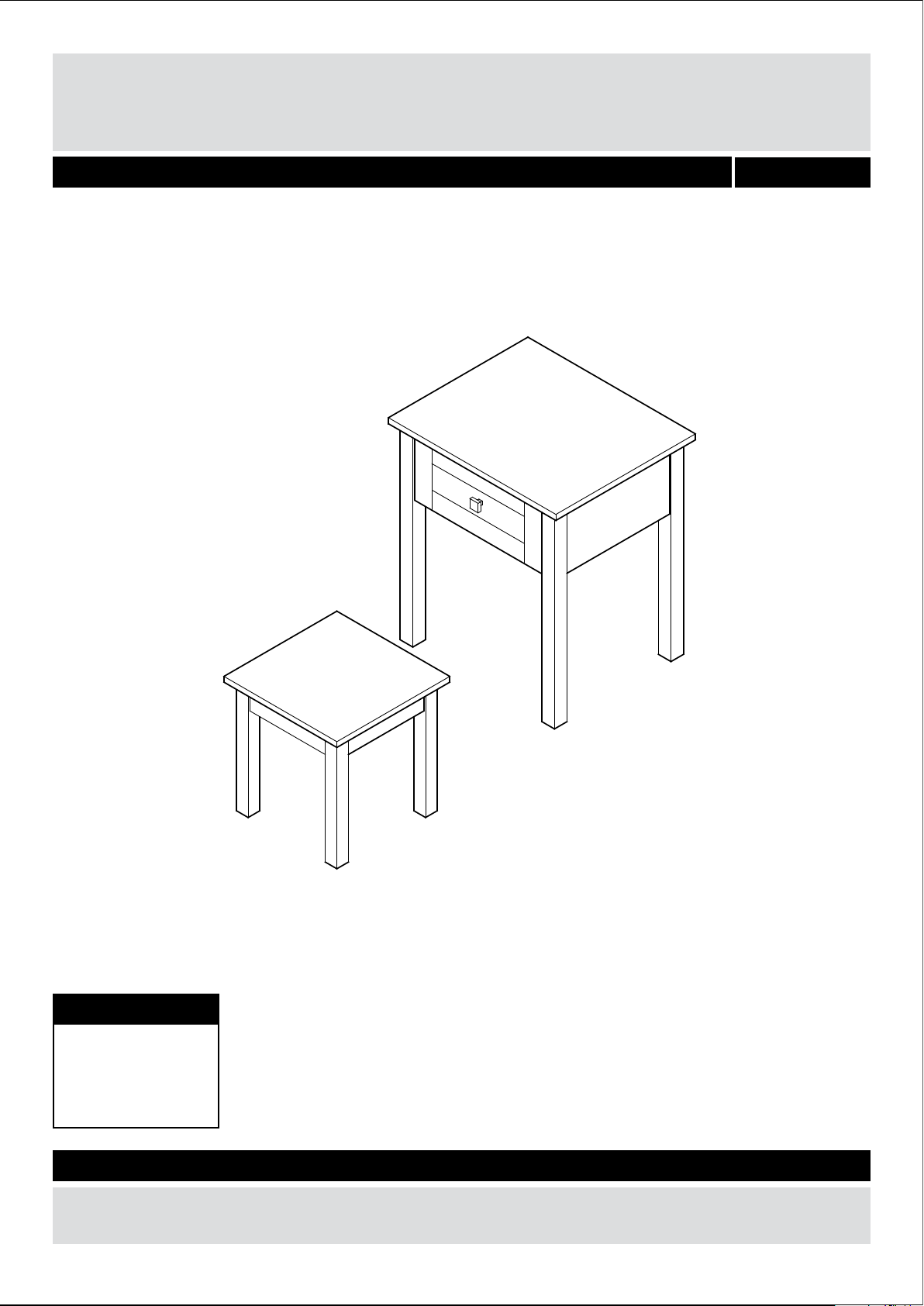
One Drawer Nesting Table
Assembly Instructions - Please keep for future reference 240/9922
Dimensions
Width - 48cm
Depth - 40cm
Height - 55cm
Important – Please read these instructions fully before starting assembly
If you need help or have damaged or missing parts, call the Customer Helpline: 08456 400800
Issue 1 - 26/03/14
Page 2
Safety and Care Advice
Important – Please read these instructions fully before starting assembly
• Check you have all the
components and tools listed on
pages 2 and 3.
plastic bags and separate them
into their groups.
• Keep children and animals
away from the work area, small
parts could choke if swallowed.
• Make sure you have enough
space to layout the parts before
starting.
Care and maintenance
• Only clean using a damp cloth
and mild detergent, do no use
bleach or abrasive cleaners.
• Do not stand or put weight on
the product, this could cause
damage.
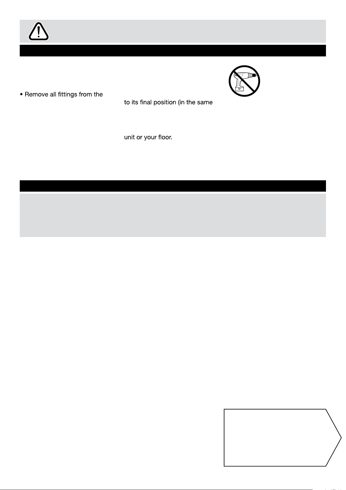
• Assemble the item as close
room) as possible.
• Assemble on a soft level
surface to avoid damaging the
• From time to time check that
there are no loose screws on
this unit.
• We do not
recommend the
use of power
drill/drivers for
inserting screws,
as this could damage the unit.
Only use hand screwdrivers.
• Dispose of all packaging
carefully and responsibly.
• This product should not be
discarded with household
waste. Take to your local
authority waste disposal centre.
Note: if required the next
page can be cut out and used
as reference throughout the
assembly. Keep this page with
these instructions for future
reference.
1
Page 3
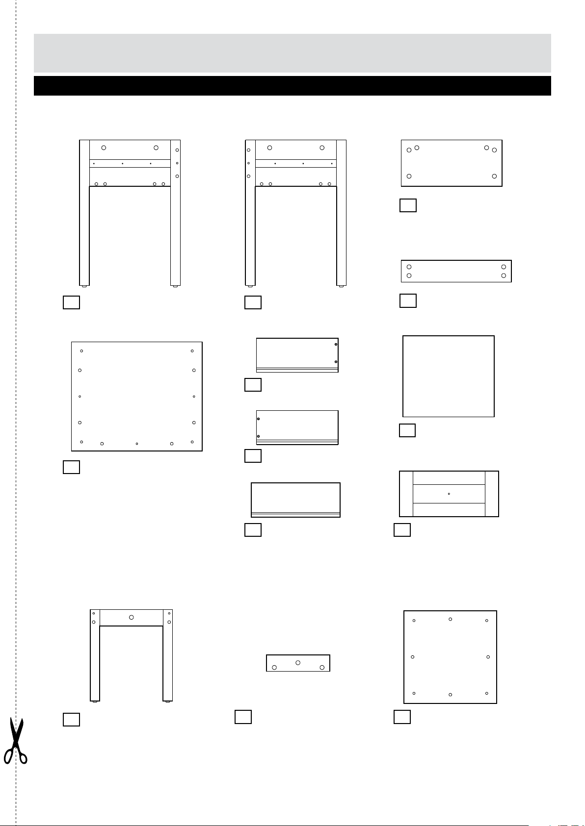
Components - Panels
Please check you have all the panels listed below
Big Table
1
Left side panel
(534 x 370mm)
2
Right side panel
(534 x 370mm)
3
Back panel
(370 x 170mm)
4
Cross rail x 2
(404 x 80mm)
Top panel
Small Table
6
Left drawer side panel
(300 x 125mm)
9
Drawer base
(335 x 298mm)
7
Right drawer side panel
(480 x 400mm)5
(300 x 125mm)
8
Drawer back panel
(325 x 125mm)
10
Drawer front
(364 x 167mm)
11
Side panel x 2
(335 x 302mm)
12
Front and rear panel x 2
(230 x 60mm)
13
Top panel
(340 x 340mm)
2
Page 4
110 115 120 125 130 135 140 145 150 155 160 165 170
105
If you have damaged or missing components,
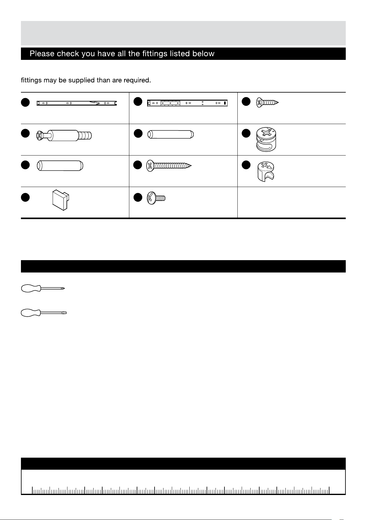
Components - Fittings
Note: The quantities below are the correct amount to complete the assembly. In some cases more
call the Customer Helpline: 08456 400800
A
D
Metal dowel x 30 Small wood dowel x 9
G
Large wood dowel x 8
J
Handle x 1
B
Runner outer piece x 2Runner inner piece x 2
E
H
35mm Screw x 4
K
Bolt x 1
Tools required
C
12mm Screw x 12
F
I
Large metal
cam x 26
Small metal
cam x 4
Phillips screwdriver
(medium & large)
Flatblade screwdriver
(medium)
Ruler - Use this ruler to help correctly identify the screws
0 5 10 15 20 25 30 35 40 45 50 55 60 65 70 75 80 85 90 95 100
3
Page 5

Assembly Instructions
Step 1
Dis-assemble Runners
To disassemble the
runners pull out the inner
piece of runners, to
seperate the Inner piece
A
and the Outer piece
B
, push and hold the
tab and then pull
completely out as shown.
Step 2
Big Table.
B
A
Attaching Runner
outer piece on Side
panel
Position Runner outer
piece onto Right side
panel and fix through
B
2
the indicated holes
shown using Screws .
C
Note: Rubber tube
on the Runner outer
piece should face to
the rear leg which has 3
holes as shown.
C
B
Rubber tube
face to the
rear leg which
has 3 holes
as shown.
C
B
2
4
Page 6

Assembly Instructions
Step 3
Screw metal dowels
D
into Right side panel
2
as shown.
Note: Insert metal
dowels as far as shown.
Do not over tighten.
Firmly push Small wood
dowels into indicated
E
holes.
Repeat Step 2 and
Step 3 on Left side
panel .
1
D
E
D
D
2
Step 4
Turn the Right side panel
2
upside down.
Firmly push Back panel
3
and Cross rails
onto Right side panel
2
, make sure the
Wood and metal dowels
enter corresponding
holes.
Insert Large metal cams
F
into the holes on
Back panel and the rails
so that they are flush.
Note: Longer
leg of the cross
on the Metal
Cams must face towards
end of panel (as shown).
4
F
Long leg.
2
3
Taped edge
face upwards.
4
4
Then, using a Philips
Screwdriver, screw all
Metal Cams clockwise
F
until they are ‘hand tight’.
Note: Tighten all cams
in this way.
5
Page 7

Assembly Instructions
Step 5
Firmly push Left side
panel onto Back
panel and Cross
rails , make sure the
wood and metal dowels
enter corresponding
holes.
Secure with Metal cams
F
.
1
3
4
3
4
F
Step 6
Lay the big table Top
panel upside down
on a soft surface.
Firmly push Large wood
dowels into indicated
holes in Top panel.
Screw metal dowels
D
as shown.
5
G
into Top panel
5
4
G
5
F
F
1
Firmly push Small wood
dowels into indicated
E
holes.
E
D
5
6
Page 8

Assembly Instructions
Step 7
Firmly push the
assembled piece from
Step 5 onto Top panel
5
, make sure the
wood and metal dowels
enter corresponding
holes.
Secure with Metal cams
F
.
F
5
Step 8
Position Runner inner
piece onto Drawer
side panels and
fix through the indicated
holes shown using
Screws .
Note: Make sure the
front end of Runner is
flush with the front edge
of drawer side as shown.
A
667
C
C
7
Make sure the front end
of Runner is flush with
the front edge of drawer
side.
7
Page 9

Assembly Instructions
Step 9
Drawer assembly
6
a: Fix drawer sides
to Drawer back panel
using screws .
H
7
8
6
8
H
7
b: Slide Drawer base
into the grooves as
shown.
c: Screw Metal
dowels into holes
on back of Drawer front
10
.
d:
against end of drawer
sides and firmly push to
make sure the Drawer
base enters the groove in
Drawer front.
D
Position drawer front
9
Foiled side
face upwards.
9
D
10
Secure with Small metal
cams .
e:
I
Attach Handle to
the Drawer front using
K
Bolt .
10
JJ
K
I
8
Page 10

Assembly Instructions
Step
Slide Drawer into the
space as shown, make
sure the Runner inner
piece enters the Runner
outer piece on both
side.
Step
Screw metal dowels
D
into Small table side
panel as shown.
10
11
11
Small Table.
E
D
Firmly push Small wood
dowels into indicated
holes.
E
Step 12
Firmly push Side panels
11
onto Front and rear
panels , make sure the
wood and metal dowels
enter corresponding
holes.
Secure with Metal
cams .
12
F
11
11
Taped edges
face upwards.
F
12
12
9
11
Page 11

Assembly Instructions
Step 13
Lay the small table Top
panel upside down
on a soft surface.
Firmly push Large wood
dowels into indicated
holes in Top panel.
Screw metal dowels
as shown.
13
G
D
into Top panel
13
D
G
13
Step
Firmly push the
assembled piece from
Step 12 onto Top panel
13
, make sure the
wood and metal dowels
enter corresponding
holes.
Secure with Metal cams
F
.
14
F
13
Assembly is complete.
If you need help or have damaged or missing parts, call the Customer Helpline: 08456 400800
Shaw Spencer Hometrading Ltd. 34-38 Vale Road, Bushey. WD23 2HE.
 Loading...